replacing BMW 540i 1997 E39 Manual PDF
[x] Cancel search | Manufacturer: BMW, Model Year: 1997, Model line: 540i, Model: BMW 540i 1997 E39Pages: 1002
Page 515 of 1002
Downloaded from www.Manualslib.com manuals search engine
170-1 9
Radiator and Cooling System
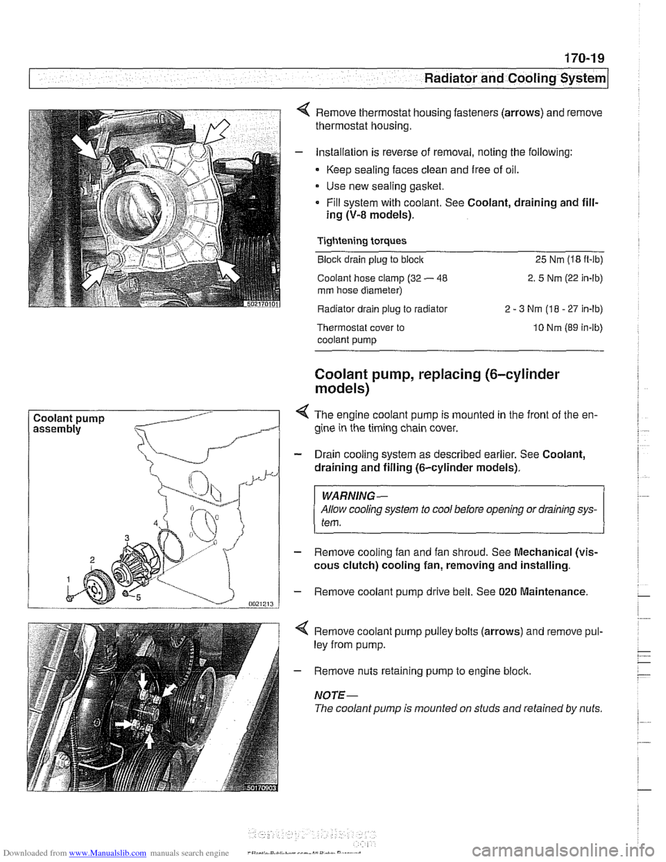
Coolant pump Remove thermostat housing fasteners
(arrows) and remove
thermostat housing.
Installation is reverse of removal, noting the following:
- Keep sealing faces clean and free of oil.
Use new sealing gasket.
Fill system with coolant. See Coolant, draining and fill-
ing
(V-8 models).
Tightening torques
Block drain plug to block 25 Nm (18 it-lb)
Coolant hose clamp (32
- 48 2. 5 Nm (22 in-lb)
mm hose diameter)
Radiator drain plug to radiator 2
- 3 Nm (18 - 27 In-lb)
Thermostat cover to
coolant pump 10 Nm (89 in-lb)
Coolant pump, replacing (6-cylinder
models)
< The engine coolant pump is mounted in the front of the en-
gine in the timing chain cover.
- Drain cooling system as described earlier. See Coolant,
draining and filling (6-cylinder models).
WARNING-
Allow cooling system to cool before opening or draining sys-
tem.
- Remove cooling fan and fan shroud. See Mechanical (vis-
cous clutch) cooling fan, removing and installing.
- Remove coolant pump drive belt. See 020 Maintenance.
4 Remove coolant pump pulley bolts (arrows) and remove pul-
ley from pump.
- Remove nuts retaining pump to engine block.
NOTE-
The coolant pump is mounted on studs and retained by nuts.
Page 516 of 1002
Downloaded from www.Manualslib.com manuals search engine
.," --
Radiator and Cooling System --- 1
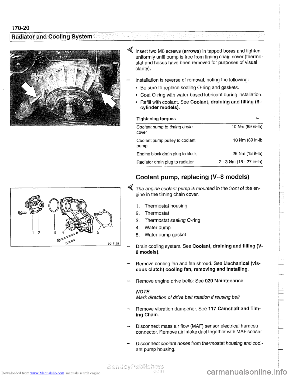
insert two M6 screws (arrows) in tapped bores and tighten
uniformly until pump is free from timing chain cover (thermo-
stat and hoses have been removed for purposes of visual
clarity).
Installation is reverse of removal, noting the following:
Be sure to replace sealing O-ring and gaskets.
Coat O-ring with water-based lubricant during installation.
Refill with coolant. See Coolant, draining and filling
(6-
cylinder models).
Tightening torques
-
Coolant pump to timing chain 10 Nm (89 in-lb)
cover
Coolant pump pulley to coolant
10 Nm (89 in-lb
pump
Engine block drain plug to block 25 Nm (1 8 It-lb)
Radiator drain plug to radiator 2 - 3 Nm (I8 - 27 in-lb)
Coolant pump, replacing (V-8 models)
I 1 < The engine coolant pump is mounted in the front of the en-
gine in ;he timing chain cover.
1. Thermostat housing
2. Thermostat
3. Thermostat sealing O-ring
4. Water pump
5. Water pump gasket
- Drain cooling system. See Coolant, draining and filling (V-
8 models).
- Remove cooling fan and fan shroud. See Mechanical (vis-
cous clutch) cooling fan, removing and installing.
- Remove engine drive belts: See 020 Maintenance.
NOTE-
Mark direction of drive belt rotation if reusing belt,
- Remove vibration dampener. See 117 Camshaft and Tim-
ing Chain.
- Disconnect mass air flow (MAF) sensor electrical harness
connector. Remove air intake duct together with
MAF sensor.
- Disconnect coolant hoses from thermostat housing and cool-
ant pump housing.
Page 523 of 1002
Downloaded from www.Manualslib.com manuals search engine
180 Exhaust System
General Exhaust System
. . . . . . . . . . . . . . . . .
Exhaust system, removing and installing
Muffler, replacing..
. . . . . . . . . . . . . . . . .
Exhaust Manifolds . . . . . . . . . . . . . . .
Exhaust manifolds, removing
and installing (M52 engine)
. . . . . . . . . .
Exhaust manifolds, removing and
installing (M52
TU and M54 engines) . . .
Exhaust manifolds, removing
and installing (M62 engine)
. . . . . . . . . .
Oxygen Sensors. . . . . . . . . . . . . . . . . . . . 180-9
Oxygen sensors (precatalyst),
replacing
(M52 TU and M54) . . . . . . . . . . . . 180-9
Oxygen sensors (post-catalyst),
replacing (M52
TU and M54) . . . . . . . . . . . . 180-9
Oxygen sensor, replacing
(M52 and M62 engine) . . . . . . . . . . . . . . . 180-10
Exhaust System Diagrams . . . . . . . . . 180-1 1
M52 engine (528i 1997-1 998) . . . . . . . . . . 180-1 1
M52
TU and M54 engines
(528i 1999-2000 and 5251 2001-2003) . . . 180-1 2
M54 engine
(530i 2001-2003) . . . . . . . . . . 180-1 3
M62 engine
(540i 1997-1 998) . . . . . . . . . . 180-1 4
M62
TU engine (540i 1999-2003 . . . . . . . 180-1 5
Page 524 of 1002
Downloaded from www.Manualslib.com manuals search engine
180-2
Exhaust System
The exhaust system is designed to be maintenance free, al-
though regular inspection is warranted due to the harsh oper-
ating conditions. Under normal conditions, the catalytic
converter does not require replacement unless it is damaged.
New fasteners, clamps, rubber mounts and gaskets should
be used when replacing exhaust components.
A liberal appli-
cation of penetrating oil to the exhaust system nuts and bolts
in advance may make removal easier.
WARNING -
The exhaust system and catalytic converter operate at
very high temperatures. Allow components to cool before
servicing. Wear protective clothing to prevent burns.
Do not use flammable chemicals near a hot
cataiyiic
converter.
Corroded exhaust system components crumble easily
and often have exposed sharp edges. To avoid injury,
wear eye protection and heavy gloves when working
Exhaust system, removing and installing
The removal and installation procedures given here are gen-
eral procedures for all models. The removal of the exhaust
system as a complete unit is recommended. Once the com-
plete system is removed from the car, individual pipes and
mufflers can be more easily replaced.
WARNING-
Exhaust gases are colorless, odorless, and very toxic. Run
the engine only in a well-ventilated area. Immediately repair
any
leaks in the exhaust system or structural damage to the
car body that
might allow exhaust gases to enter the passen-
ger compartment.
CAUTION-
Use care not to drag or bang oxygen sensors. Oxygen sen-
sors can be easily ruined.
Page 526 of 1002
Downloaded from www.Manualslib.com manuals search engine
/Exhaust System Muffler, replacing
BMW offers individual mufflers as replacement parts for the
original one-piece assembly. Replacement of a rear muffler
may be possible with the system installed on the car. Re-
placement of the front or middle muffler should only be done
with the exhaust removed from the car.
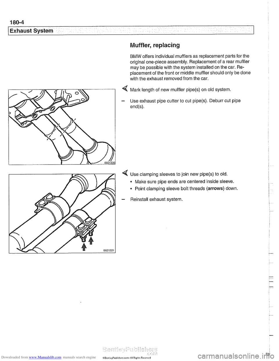
< Mark length of new muffler pipe(s) on old system.
- Use exhaust pipe cutter to cut pipe(s). Deburr cut pipe
end@).
4 Use clamping sleeves to join new pipe(s) to old.
Make sure pipe ends are centered inside sleeve.
Point clamping sleeve bolt threads
(arrows) down.
- Reinstall exhaust system.
Page 531 of 1002
Downloaded from www.Manualslib.com manuals search engine
-- -
Exhaust System
Oxygen sensors (precatalyst), replacing
(M52 TU and M54)
The precatalyst oxygen sensors are installed at the top of the
exhaust manifolds.
WARNING-
Allow components to cool before servicing.
- Using BMW scan tool DlSplus (Diagnostic Information Sys-
tem) or equivalent, read out and clear ECM fault codes.
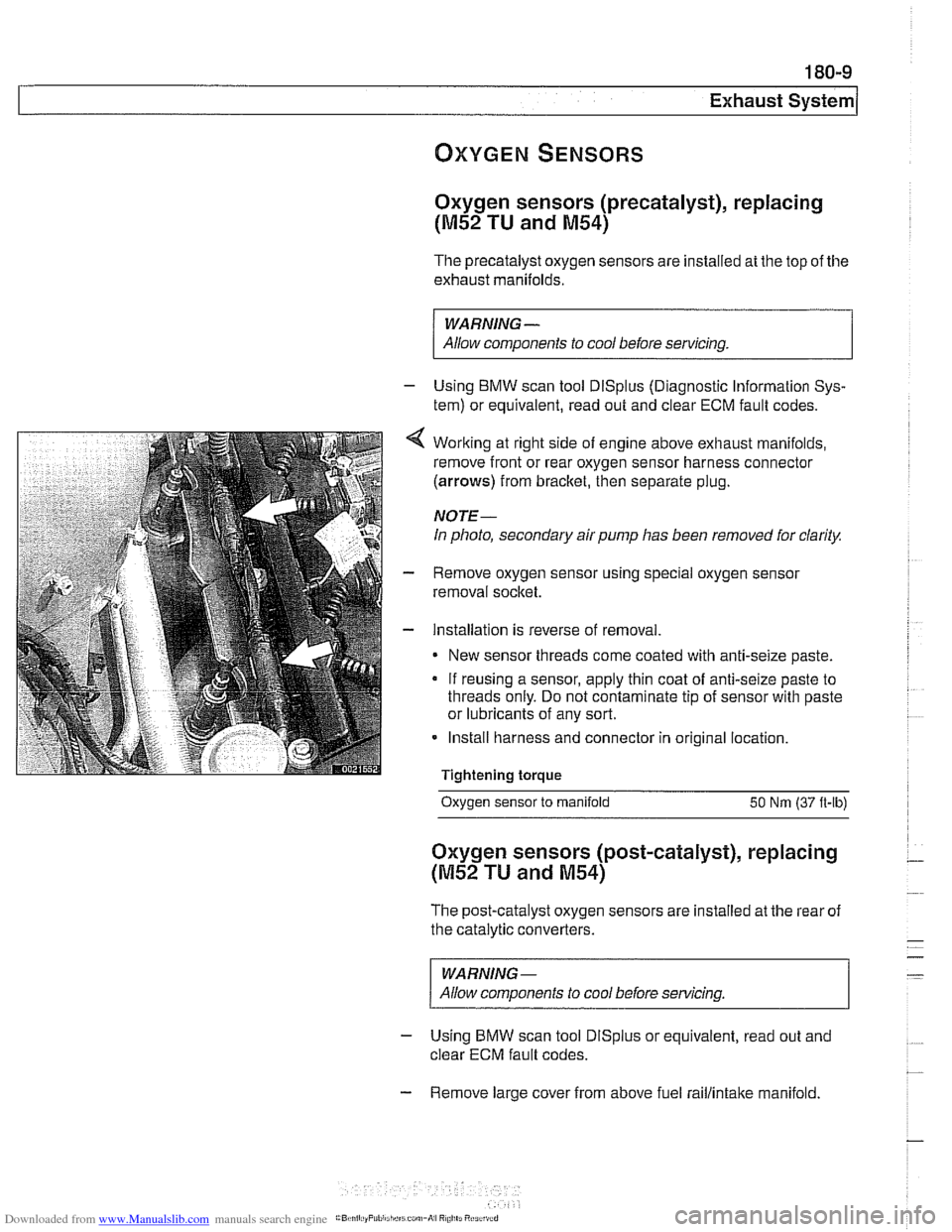
Working at right side of engine above exhaust manifolds,
remove front or rear oxygen sensor harness connector
(arrows) from bracket, then separate plug.
NOTE-
In photo, secondary air pump has been removed for clarity.
Remove oxygen sensor using special oxygen sensor
removal socket.
Installation is reverse of removal
New sensor threads come coated with anti-seize paste.
If reusing a sensor, apply thin coat of anti-seize paste to
threads only. Do not contaminate tip of sensor with paste
or lubricants of any sort.
Install harness and connector in original location.
Tightening torque
- -.
Oxygen sensor to manifold 50 Nm (37 ft-lb)
Oxygen sensors (post-catalyst), replacing
(M52 TU and M54)
The post-catalyst oxygen sensors are installed at the rear of
the catalytic converters.
WARNING-
Allow components to cool before servicing
- Using BMW scan tool DlSplus or equivalent, read out and
clear ECM fault codes.
- Remove large cover from above fuel raillintake manifold.
Page 532 of 1002
Downloaded from www.Manualslib.com manuals search engine
Exhaust System
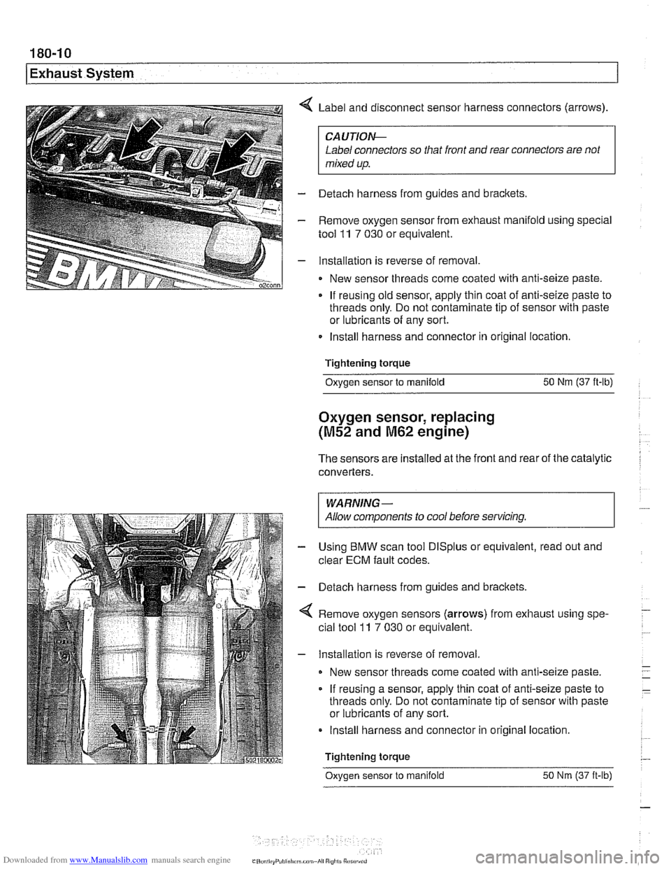
Label and disconnect sensor harness connectors (arrows).
CAUTlOI\C
Label connectors so that front and rear connectors are not
mixed up.
- Detach harness from guides and brackets.
- Remove oxygen sensor from exhaust manifold using special
tool
11 7 030 or equivalent.
- Installation is reverse of removal
New sensor threads come coated with anti-seize paste.
If reusing old sensor, apply thin coat of anti-seize paste to
threads only. Do not contaminate tip of sensor with paste
or lubricants of any sort.
Install harness and connector in original location.
Tightening torque
Oxygen sensor to manifold 50 Nm (37 ft-lb)
Oxygen sensor, replacing
(M52 and M62 engine)
The sensors are installed at the front and rear of the catalytic
converters.
I WARNING- I
I Allow components to cool before servicing. I
Using BMW scan tool DlSplus or equivalent, read out and
clear
ECM fault codes.
Detach harness from guides and brackets.
Remove oxygen sensors (arrows) from exhaust using spe-
cial tool
ll 7 030 or equivalent.
Installation is reverse of removal
New sensor threads come coated with anti-seize paste.
If reusing a sensor, apply thin coat of anti-seize paste to
threads only. Do not contaminate tip of sensor with paste
or lubricants of any sort.
Install harness and connector in original location.
Tightening torque
Oxvaen sensor to manifold 50 Nm (37 it-lb)
Page 543 of 1002
Downloaded from www.Manualslib.com manuals search engine
210 Clutch
........................... General .21 0.2
........................ Special tools .21 0.2
Clutch Hydraulics ................. .21 0.4
Clutch hydraulic system.
bleeding and flushing
................. .21 0.4
Clutch master cylinder. replacing
........ .21 0.6
Clutch slave cylinder. replacing ......... .21 0.8 Flywheel. removing
and installing
................... (6 cylinder engine) 210-12
Flywheel. removing and installing
(V-8 engine) ....................... 21 0-1 3
Transmission pilot bearing. replacing .... 210-1 5
Clutch. installing (non-SAC components) . 210-1 6
Clutch. installing (new SAC components)
. 21 0-17
Clutch.
install in^ (used SAC components) 210-19
Clutch Mechanical ................. .21 0.9 self-adjusting crutch (SAC). breaking in : . 210-21
..................... Clutch variations .21 0.9
................... Clutch. removing .21 0.1 1
Clutch components. inspecting
........ .21 0.1 1
Page 548 of 1002
Downloaded from www.Manualslib.com manuals search engine
21 0-6
1 Clutch
Hydraulic system, bleeding
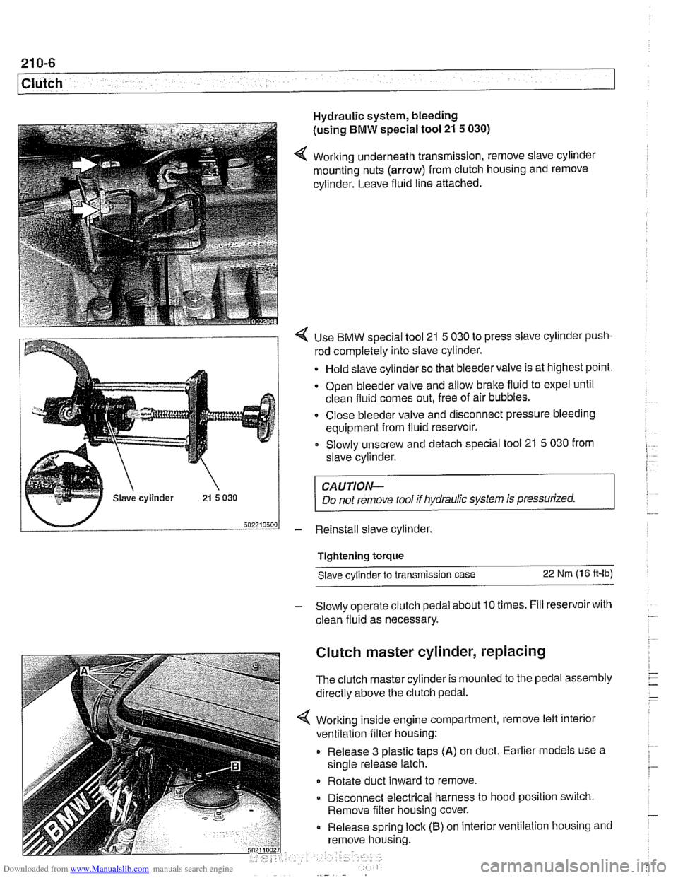
(using
BMW special tool 21 5 030)
4 Working underneath transmission, remove slave cylinder
mounting nuts (arrow) from clutch housing and remove
cylinder. Leave fluid line attached.
4 Use BMW special tool 21 5 030 to press slave cylinder push-
rod completely into slave cylinder.
Hold slave cylinder so that bleeder valve is at highest point.
Open bleeder valve and allow brake fluid to expel until
clean fluid comes out, free of air bubbles.
* Close bleeder valve and disconnect pressure bleeding
equipment from fluid reservoir.
Slowly unscrew and detach special tool 21
5 030 from
slave cylinder.
CAUTION-
Do not remove tool if hydraulic system is pressurized.
- Reinstall slave cylinder.
Tightening torque Slave cylinder to transmission case
22 Nm (1 6 ft-lb)
- Slowly operate clutch pedal about 10 times. Fill reservoir with
clean fluid as necessary.
Clutch master cylinder, replacing
The clutch master cylinder is mounted to the pedal assembly
directly above the clutch pedal.
Working inside engine compartment, remove left interior
ventilation filter housing:
Release 3 plastic taps
(A) on duct. Earlier models use a
single release latch.
Rotate duct inward to remove
Disconnect electrical harness to hood position switch.
Remove filter housing cover.
Release spring
loclc (B) on interior ventilation housing and
remove housing.
Page 550 of 1002
Downloaded from www.Manualslib.com manuals search engine
21 0-8
Clutch
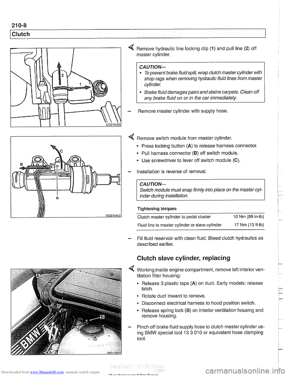
4 Remove hydraulic line locking clip (1) and pull line (2) off
master cylinder.
CAUTION-
. To prevent brake fluidspill, wrap clutch master cylinder with
shop rags when removing hydraulic fluid lines from master
cylinder.
* Brake fluid damages paint andstains carpets. Clean off
any brake fluid on or
in the car immediately.
- Remove master cylinder with supply hose
4 Remove switch module from master cylinder.
Press locking button
(A) to release harness connector.
Pull harness connector
(8) off switch module.
Use screwdriver to lever
off switch module (C).
- Installation is reverse of removal.
CA UTlON-
Switch module must snap firmly into place on the master cyl-
inder during installation.
Tightening torques
Clutch master cylinder to pedal cluster
10 Nm (89 in-lb)
Fluid line
to master cylinder or slave cylinder 17 Nm (13 ft-lb)
- Fill fluid reservoir with clean fluid. Bleed clutch hydraulics as
described earlier.
Clutch slave cylinder, replacing
4 Working inside engine compartment, remove left interiorven-
tilation filter housing:
Release
3 plastic taps (A) on duct. Early models: release
latch.
Rotate duct inward to remove.
Disconnect electrical harness to hood position switch.
Release spring lock (B) on interior ventilation housing and
remove housing.
- Pinch off brake fluid supply hose to clutch master cylinder us-
ing BMW special tool
13 3 01 0 or equivalent hose clamping
tool.