CHERY TIGGO 2009 Service Repair Manual
Manufacturer: CHERY, Model Year: 2009, Model line: TIGGO, Model: CHERY TIGGO 2009Pages: 1903, PDF Size: 33.38 MB
Page 1351 of 1903
Downloaded from www.Manualslib.com manuals search engine DIAGNOSIS & TESTING
Vehicle Inspection
Visual inspection of the vehicle is recommended prior to road testing or performing any other procedure. Raise the
vehicle on a suitable hoist.
Inspect the following:
•Inspect tires and wheels for damage, mud packing and unusual wear; correct as necessary.
• Check and adjust tire pressure to the pressure listed on the label attached to the driver’s door opening.
Tire and Wheel Vibration
Tire and wheel imbalance, runout and force variation can cause vehicles to exhibit steering wheel vibration.
NOTE :
Balance equipment must be calibrated and maintained per equipment manufacturer’s specifications.
Tire Wear Patterns
Tire wear patterns can be traced to the following tire conditions:
•Under inflation will cause wear on the shoulders of tire.
• Over inflation will cause wear at the center of tire.
• Excessive camber causes the tire to run at an angle to the road. One side of tread is then worn more than the
other.
• Excessive toe-in or toe-out causes wear on the tread edges and a feathered effect across the tread.
NOTE :
Tread wear indicators are molded into the bottom of the tread grooves. When tread depth is 1.6 mm, the tread wear
indicators will appear as a band. Tire replacement is necessary when indicators appear in two or more grooves, or
if localized balding occurs.
Wheel Out-Of-Round Inspection
• Raise vehicle and securely support it.
• Attach a dial indicator on the edge of the rim and measure its unevenness.
• Replace the rim if necessary.10
10–50Chery Automobile Co., Ltd.
Page 1352 of 1903
Downloaded from www.Manualslib.com manuals search engine ON-VEHICLE SERVICE
Tire Repair
Description
Tires are designed and engineered for each specific vehicle. They provide the best overall performance for normal
operation. The ride and handling characteristics match the vehicle’s requirements. With proper care they will give
excellent reliability, traction, skid resistance, and tread life.
WARNING!
Failure to equip the vehicle with tires having adequate speed capability can result in sudden tire failure.
In order to maintain the speed capability of the vehicle, replacement tires must have speed ratings equal to or
higher than those fitted to the vehicle as original equipment. If tires with lower speed ratings are fitted, the vehi-
cle’s handling may be affected and the speed capability of the vehicle may be lowered to the maximum speed
capability of the replacement tires. To avoid an accident resulting in severe or fatal injury, consult the tire man-
ufacturer in regards to maximum speed ratings.
Replacement Procedure
Note the following guidelines when replacing a tire:
•It is recommended that tires equivalent to the original equipment tires be used when replacement is needed.
• Failure to use equivalent replacement tires may adversely affect the safety and handling of the vehicle.
• The use of tires smaller than the minimum tire size approved for the vehicle can result in tire overloading and
failure.
• Use tires that have the approved load rating for the vehicle and never overload them.
• Failure to equip the vehicle with tires having adequate speed capability can result in sudden tire failure and
loss of vehicle control.
• The use of oversize tires may cause interference with vehicle components. Under extremes of suspension and
steering travel, interference with vehicle components may cause tire damage.
Perform the following when replacing a tire: 1. Raise and support the vehicle.
2. Remove the wheel mounting nuts and the wheel assembly.
3. Deflate the tire completely before removing the tire from the wheel.
4. Use lubrication such as a mild soap solution when dismounting or mounting tire.
5. Replace the tire with a tire approved for the vehicle.
6. Use tools free of burrs or sharp edges which could damage the tire or wheel rim.
7. Before mounting tire on wheel, make sure all rust is removed from the rim bead and repaint if necessary.
8. Balance the wheel assembly.
9. Install the wheel assembly and install the wheel mounting nuts. (Tighten: Wheel mounting nuts to 110 N·m)
Repair Procedure
Note the following guidelines when performing a tire repair:
•For proper repairing, a radial tire must be removed from the wheel.
• Repairs should only be made if the defect, or puncture, is in the tread area.
• The tire should be replaced if the puncture is located in the sidewall.
Perform the following when repairing a tire: 1. Raise and support the vehicle.
2. Remove the wheel mounting nuts and the wheel assembly.
3. Deflate the tire completely before removing the tire from the wheel.
4. Use lubrication such as a mild soap solution when dismounting or mounting tire.
5. Repair the tire only if the defect, or puncture, is in the tread area.
6. Use tools free of burrs or sharp edges which could damage the tire or wheel rim.
7. Before mounting tire on wheel, make sure all rust is removed from the rim bead and repaint if necessary.
10–51Chery Automobile Co., Ltd.
Page 1353 of 1903
Downloaded from www.Manualslib.com manuals search engine 8. Install the wheel assembly and install the wheel mounting nuts.(Tighten: Wheel mounting nuts to 110 N·m)
Wheel Assembly
Description
Original equipment wheels are designed for operation up to the specified maximum vehicle capacity.
Inspect wheels for the following:
•Dents or cracks
• Damaged wheel bolt holes
• Air leaks from any area or surface of the rim
• Excessive run out
NOTE :
Do not attempt to repair a wheel by hammering, heating or welding.
NOTE :
The wheel nuts are designed for specific applications. Do not use replacement bolts with a different design or lesser
quality.
Removal & Installation
1. Raise and support the vehicle.
2. If the vehicle is equipped with wheel center caps that cover the wheel nuts, remove the cap with an appropriate removal tool utilizing the notch located between the wheel and the outer edge of the cap.
NOTE: Use care not to damage the finish on the wheel.
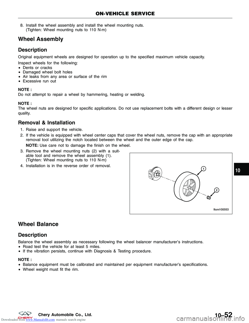
3. Remove the wheel mounting nuts (2) with a suit- able tool and remove the wheel assembly (1).
(Tighten: Wheel mounting nuts to 110 N·m)
4. Installation is in the reverse order of removal.
Wheel Balance
Description
Balance the wheel assembly as necessary following the wheel balancer manufacturer’s instructions.
• Road test the vehicle for at least 5 miles.
• If the vibration persists, continue with Diagnosis & Testing procedure.
NOTE :
• Balance equipment must be calibrated and maintained per equipment manufacturer’s specifications.
• Wheel weight must fit the rim.
ON-VEHICLE SERVICE
LTSM100053
10
10–52Chery Automobile Co., Ltd.
Page 1354 of 1903
Downloaded from www.Manualslib.com manuals search engine Wheel Balance Procedure
1. Raise and support the vehicle.
2. Remove the wheel mounting nuts and the wheelassembly.
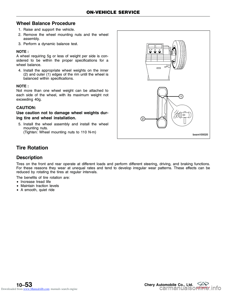
3. Perform a dynamic balance test.
NOTE :
A wheel requiring 5g or less of weight per side is con-
sidered to be within the proper specifications for a
wheel balance. 4. Install the appropriate wheel weights on the inner (2) and outer (1) edges of the rim until the wheel is
balanced within specifications.
NOTE :
Not more than one wheel weight can be attached to
each side of the wheel, with its maximum weight not
exceeding 40g.
CAUTION:
Use caution not to damage wheel weights dur-
ing tire and wheel installation.
5. Install the wheel assembly and install the wheel mounting nuts.
(Tighten: Wheel mounting nuts to 110 N·m)
Tire Rotation
Description
Tires on the front and rear operate at different loads and perform different steering, driving, and braking functions.
For these reasons they wear at unequal rates and tend to develop irregular wear patterns. These effects can be
reduced by rotating the tires at regular intervals.
The benefits of tire rotation are:
•Increase tread life
• Maintain traction levels
• A smooth, quiet ride
ON-VEHICLE SERVICE
BESM100020
10–53Chery Automobile Co., Ltd.
Page 1355 of 1903
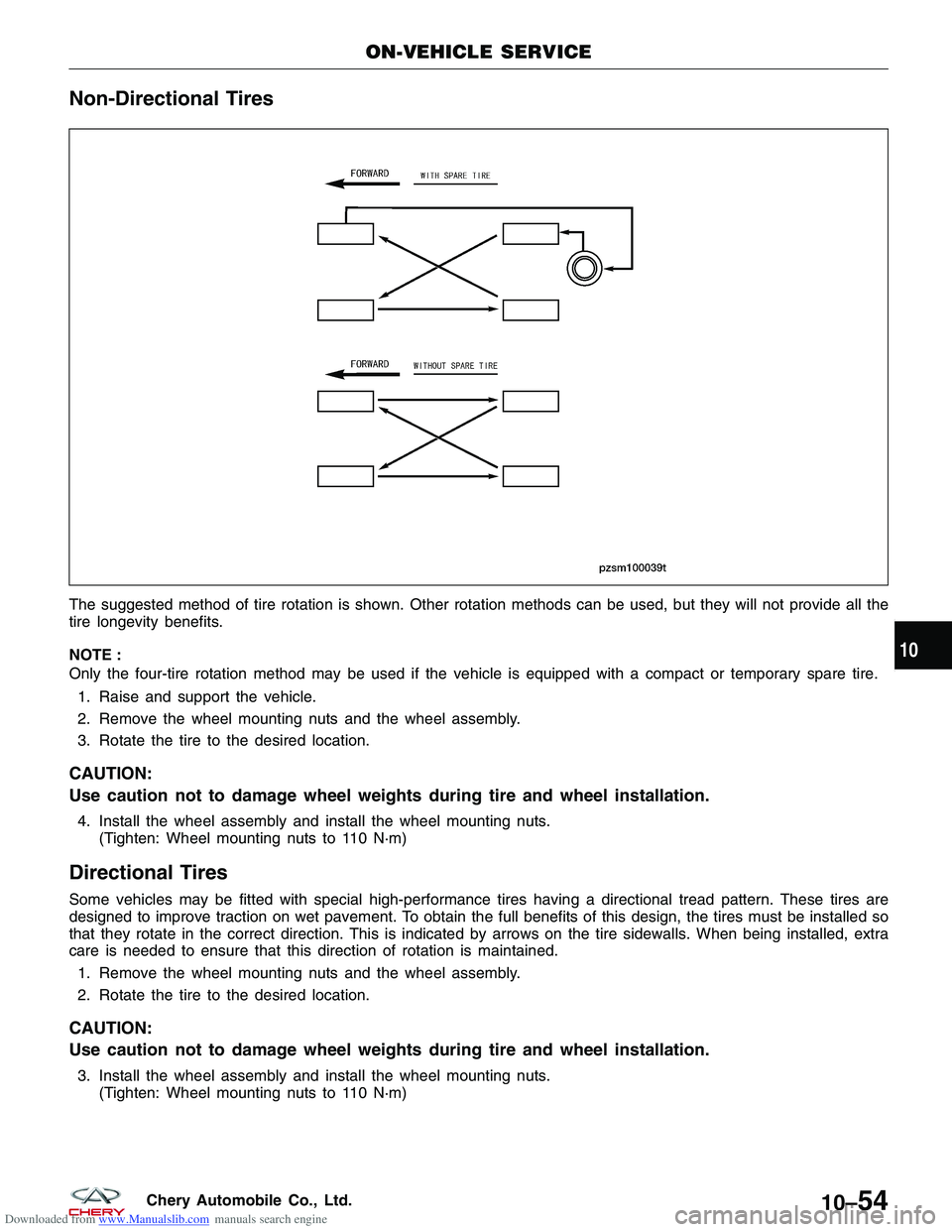
Downloaded from www.Manualslib.com manuals search engine Non-Directional Tires
The suggested method of tire rotation is shown. Other rotation methods can be used, but they will not provide all the
tire longevity benefits.
NOTE :
Only the four-tire rotation method may be used if the vehicle is equipped with a compact or temporary spare tire.1. Raise and support the vehicle.
2. Remove the wheel mounting nuts and the wheel assembly.
3. Rotate the tire to the desired location.
CAUTION:
Use caution not to damage wheel weights during tire and wheel installation.
4. Install the wheel assembly and install the wheel mounting nuts. (Tighten: Wheel mounting nuts to 110 N·m)
Directional Tires
Some vehicles may be fitted with special high-performance tires having a directional tread pattern. These tires are
designed to improve traction on wet pavement. To obtain the full benefits of this design, the tires must be installed so
that they rotate in the correct direction. This is indicated by arrows on the tire sidewalls. When being installed, extra
care is needed to ensure that this direction of rotation is maintained.
1. Remove the wheel mounting nuts and the wheel assembly.
2. Rotate the tire to the desired location.
CAUTION:
Use caution not to damage wheel weights during tire and wheel installation.
3. Install the wheel assembly and install the wheel mounting nuts. (Tighten: Wheel mounting nuts to 110 N·m)
ON-VEHICLE SERVICE
PZSM100039T
10
10–54Chery Automobile Co., Ltd.
Page 1356 of 1903
Downloaded from www.Manualslib.com manuals search engine STEERING
11
CONTENTSpage
Steering System ..................................................................... 11-1
Steering Column ..................................................................... 11-8
Steering Gear ...................................................................... 11-18
Power Steering Pump ................................................................ 11-31
STEERING SYSTEM
GENERAL INFORMATION11-2
Description 11-2
Operation 11-2
Specifications 11-3
Special Tools 11-3
DIAGNOSIS & TESTING11-4
Power Steering Troubleshooting Chart 11-4
Power Steering Fluid Troubleshooting
Chart 11-5
ON-VEHICLE SERVICE11-6
Power Steering Filling and Flushing 11-6
Filling 11-6
Flushing 11-6
Inspection 11-7
11
11 –1Chery Automobile Co., Ltd.
Page 1357 of 1903
Downloaded from www.Manualslib.com manuals search engine GENERAL INFORMATION
Description
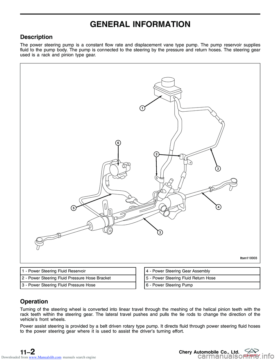
The power steering pump is a constant flow rate and displacement vane type pump. The pump reservoir supplies
fluid to the pump body. The pump is connected to the steering by the pressure and return hoses. The steering gear
used is a rack and pinion type gear.
Operation
Turning of the steering wheel is converted into linear travel through the meshing of the helical pinion teeth with the
rack teeth within the steering gear. The lateral travel pushes and pulls the tie rods to change the direction of the
vehicle’s front wheels.
Power assist steering is provided by a belt driven rotary type pump. It directs fluid through power steering fluid hoses
to the power steering gear where it is used to assist the driver’s turning effort.
1 - Power Steering Fluid Reservoir
2 - Power Steering Fluid Pressure Hose Bracket
3 - Power Steering Fluid Pressure Hose4 - Power Steering Gear Assembly
5 - Power Steering Fluid Return Hose
6 - Power Steering Pump
LTSM110003
11 –2Chery Automobile Co., Ltd.
Page 1358 of 1903
Downloaded from www.Manualslib.com manuals search engine Manual steering control of the vehicle can be maintained if power steering assist is lost. However, under this condi-
tion, steering effort is significantly increased.
WARNING!
Power steering fluid, engine parts and exhaust system may be extremely hot if engine has been running. Do not
start engine with any loose or disconnected hoses. Do not allow hoses to touch hot exhaust manifold or cata-
lyst. Fluid level should be checked with the engine off to prevent personal injury from moving parts.
Specifications
Fluid Specifications
DESCRIPTIONCAPACITY (L)
Power Steering Fluid (ATF III) 1.1
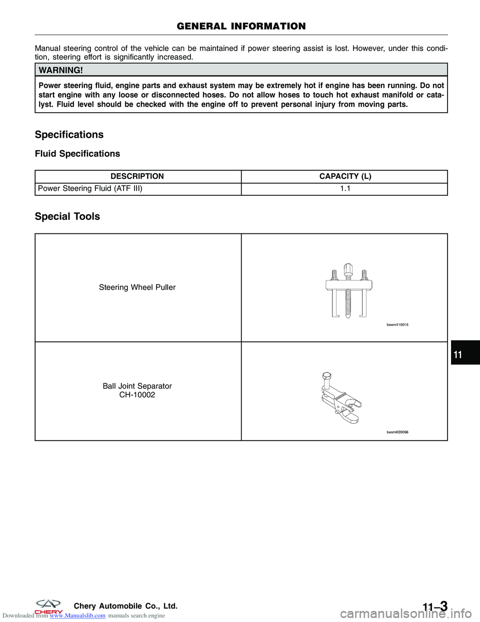
Special Tools
Steering Wheel Puller
Ball Joint Separator
CH-10002
GENERAL INFORMATION
11
11 –3Chery Automobile Co., Ltd.
Page 1359 of 1903
Downloaded from www.Manualslib.com manuals search engine DIAGNOSIS & TESTING
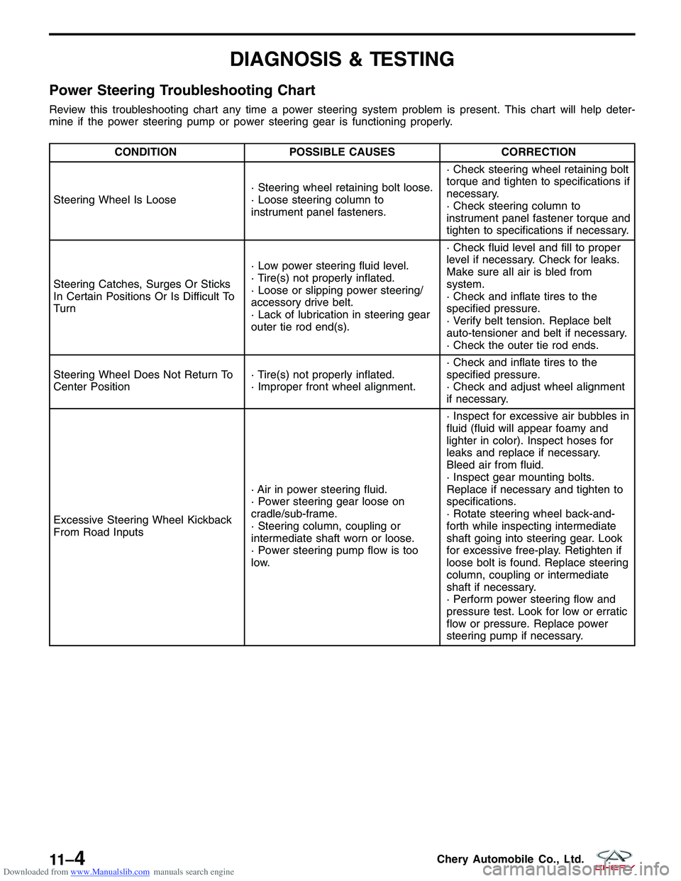
Power Steering Troubleshooting Chart
Review this troubleshooting chart any time a power steering system problem is present. This chart will help deter-
mine if the power steering pump or power steering gear is functioning properly.
CONDITIONPOSSIBLE CAUSES CORRECTION
Steering Wheel Is Loose · Steering wheel retaining bolt loose.
· Loose steering column to
instrument panel fasteners.· Check steering wheel retaining bolt
torque and tighten to specifications if
necessary.
· Check steering column to
instrument panel fastener torque and
tighten to specifications if necessary.
Steering Catches, Surges Or Sticks
In Certain Positions Or Is Difficult To
Turn · Low power steering fluid level.
· Tire(s) not properly inflated.
· Loose or slipping power steering/
accessory drive belt.
· Lack of lubrication in steering gear
outer tie rod end(s).· Check fluid level and fill to proper
level if necessary. Check for leaks.
Make sure all air is bled from
system.
· Check and inflate tires to the
specified pressure.
· Verify belt tension. Replace belt
auto-tensioner and belt if necessary.
· Check the outer tie rod ends.
Steering Wheel Does Not Return To
Center Position · Tire(s) not properly inflated.
· Improper front wheel alignment.· Check and inflate tires to the
specified pressure.
· Check and adjust wheel alignment
if necessary.
Excessive Steering Wheel Kickback
From Road Inputs · Air in power steering fluid.
· Power steering gear loose on
cradle/sub-frame.
· Steering column, coupling or
intermediate shaft worn or loose.
· Power steering pump flow is too
low.· Inspect for excessive air bubbles in
fluid (fluid will appear foamy and
lighter in color). Inspect hoses for
leaks and replace if necessary.
Bleed air from fluid.
· Inspect gear mounting bolts.
Replace if necessary and tighten to
specifications.
· Rotate steering wheel back-and-
forth while inspecting intermediate
shaft going into steering gear. Look
for excessive free-play. Retighten if
loose bolt is found. Replace steering
column, coupling or intermediate
shaft if necessary.
· Perform power steering flow and
pressure test. Look for low or erratic
flow or pressure. Replace power
steering pump if necessary.
11 –4Chery Automobile Co., Ltd.
Page 1360 of 1903
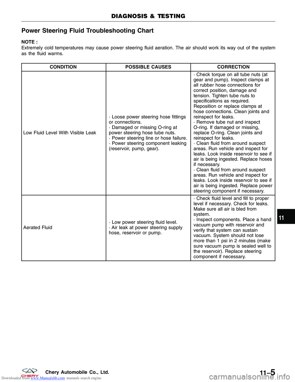
Downloaded from www.Manualslib.com manuals search engine Power Steering Fluid Troubleshooting Chart
NOTE :
Extremely cold temperatures may cause power steering fluid aeration. The air should work its way out of the system
as the fluid warms.
CONDITIONPOSSIBLE CAUSES CORRECTION
Low Fluid Level With Visible Leak · Loose power steering hose fittings
or connections.
· Damaged or missing O-ring at
power steering hose tube nuts.
· Power steering line or hose failure.
· Power steering component leaking
(reservoir, pump, gear).· Check torque on all tube nuts (at
gear and pump). Inspect clamps at
all rubber hose connections for
correct position, damage and
tension. Tighten tube nuts to
specifications as required.
Reposition or replace clamps at
hose connections. Clean joints and
reinspect for leaks.
· Remove tube nut and inspect
O-ring. If damaged or missing,
replace O-ring. Clean joints and
reinspect for leaks.
· Clean fluid from around suspect
areas. Run vehicle and inspect for
leaks. Look inside reservoir to see if
air is being ingested. Replace hoses
if necessary.
· Clean fluid from around suspect
areas. Run vehicle and inspect for
leaks. Look inside reservoir to see if
air is being ingested. Replace power
steering component if necessary.
Aerated Fluid · Low power steering fluid level.
· Air leak at power steering supply
hose, reservoir or pump.· Check fluid level and fill to proper
level if necessary. Check for leaks.
Make sure all air is bled from
system.
· Inspect components. Place a hand
vacuum pump with reservoir and
verify that system can sustain
vacuum. System should not lose
more than 1 psi in 2 minutes (make
sure vacuum pump is sealed well to
the reservoir). Replace steering
component if necessary.
DIAGNOSIS & TESTING
11
11 –5Chery Automobile Co., Ltd.