CHERY TIGGO 2009 Service Repair Manual
Manufacturer: CHERY, Model Year: 2009, Model line: TIGGO, Model: CHERY TIGGO 2009Pages: 1903, PDF Size: 33.38 MB
Page 1341 of 1903
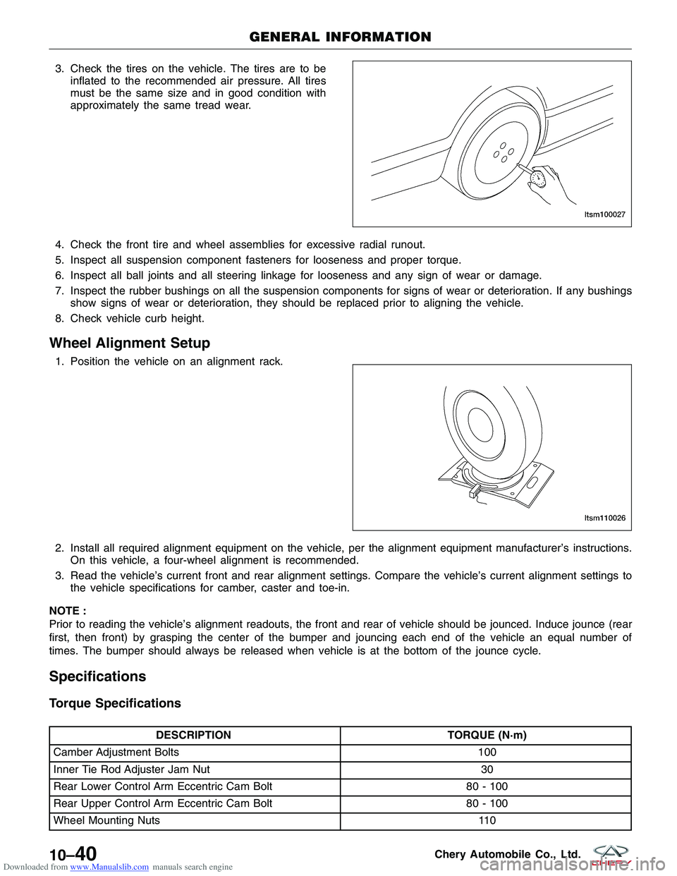
Downloaded from www.Manualslib.com manuals search engine 3. Check the tires on the vehicle. The tires are to beinflated to the recommended air pressure. All tires
must be the same size and in good condition with
approximately the same tread wear.
4. Check the front tire and wheel assemblies for excessive radial runout.
5. Inspect all suspension component fasteners for looseness and proper torque.
6. Inspect all ball joints and all steering linkage for looseness and any sign of wear or damage.
7. Inspect the rubber bushings on all the suspension components for signs of wear or deterioration. If any bushings show signs of wear or deterioration, they should be replaced prior to aligning the vehicle.
8. Check vehicle curb height.
Wheel Alignment Setup
1. Position the vehicle on an alignment rack.
2. Install all required alignment equipment on the vehicle, per the alignment equipment manufacturer’s instructions. On this vehicle, a four-wheel alignment is recommended.
3. Read the vehicle’s current front and rear alignment settings. Compare the vehicle’s current alignment settings to the vehicle specifications for camber, caster and toe-in.
NOTE :
Prior to reading the vehicle’s alignment readouts, the front and rear of vehicle should be jounced. Induce jounce (rear
first, then front) by grasping the center of the bumper and jouncing each end of the vehicle an equal number of
times. The bumper should always be released when vehicle is at the bottom of the jounce cycle.
Specifications
Torque Specifications
DESCRIPTION TORQUE (N·m)
Camber Adjustment Bolts 100
Inner Tie Rod Adjuster Jam Nut 30
Rear Lower Control Arm Eccentric Cam Bolt 80 - 100
Rear Upper Control Arm Eccentric Cam Bolt 80 - 100
Wheel Mounting Nuts 110
GENERAL INFORMATION
LTSM100027
LTSM110026
10–40Chery Automobile Co., Ltd.
Page 1342 of 1903
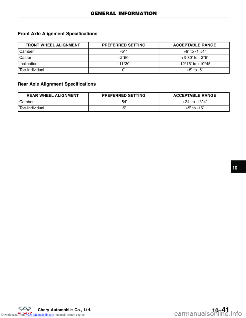
Downloaded from www.Manualslib.com manuals search engine Front Axle Alignment Specifications
FRONT WHEEL ALIGNMENTPREFERRED SETTINGACCEPTABLE RANGE
Camber -51’+9’ to -1°51’
Caster +2°50’+3°30’ to +2°5’
Inclination +11°30’+12°15’ to +10°45’
Toe-Individual 0’+5’ to -5’
Rear Axle Alignment Specifications
REAR WHEEL ALIGNMENT PREFERRED SETTINGACCEPTABLE RANGE
Camber -54’+24’ to -1°24’
Toe-Individual -5’+5’ to -15’
GENERAL INFORMATION
10
10–41Chery Automobile Co., Ltd.
Page 1343 of 1903
Downloaded from www.Manualslib.com manuals search engine DIAGNOSIS & TESTING
Vehicle Inspection
Inspect the following for damage:
•Inspect the tires.
• Inspect the rims.
Replace any tire or rim that is found to be damaged.
Tire Wear
Inspect the following for accurate tire wear:
• Check the depth of tire remaining tread.
• Standard tire: not less than 1.6 mm.
• Snow tire: 50% tire tread.
If the tread is below the specifications, the tire should be replaced.
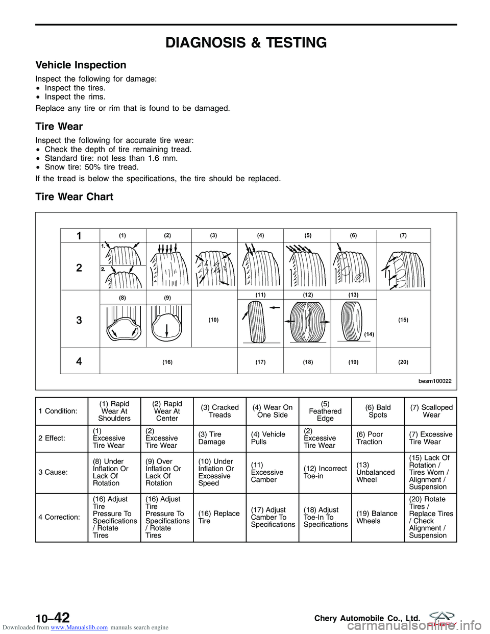
Tire Wear Chart
1 Condition: (1) Rapid
Wear At
Shoulders (2) Rapid
Wear At Center (3) Cracked
Treads (4) Wear On
One Side (5)
Feathered Edge (6) Bald
Spots (7) Scalloped
Wear
2 Effect: (1)
Excessive
Tire Wear(2)
Excessive
Tire Wear
(3) Tire
Damage
(4) Vehicle
Pulls(2)
Excessive
Tire Wear(6) Poor
Traction
(7) Excessive
Tire Wear
3 Cause: (8) Under
Inflation Or
Lack Of
Rotation(9) Over
Inflation Or
Lack Of
Rotation(10) Under
Inflation Or
Excessive
Speed
(11)
Excessive
Camber
(12) Incorrect
Toe-in(13)
Unbalanced
Wheel(15) Lack Of
Rotation /
Tires Worn /
Alignment /
Suspension
4 Correction: (16) Adjust
Tire
Pressure To
Specifications
/ Rotate
Tires(16) Adjust
Tire
Pressure To
Specifications
/ Rotate
Tires
(16) Replace
Tire
(17) Adjust
Camber To
Specifications(18) Adjust
Toe-In To
Specifications
(19) Balance
Wheels(20) Rotate
Tires /
Replace Tires
/ Check
Alignment /
Suspension
BESM100022
10–42Chery Automobile Co., Ltd.
Page 1344 of 1903
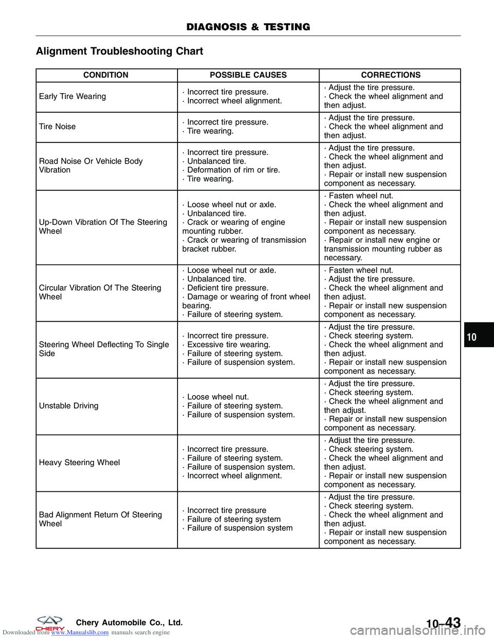
Downloaded from www.Manualslib.com manuals search engine Alignment Troubleshooting Chart
CONDITIONPOSSIBLE CAUSES CORRECTIONS
Early Tire Wearing · Incorrect tire pressure.
· Incorrect wheel alignment.· Adjust the tire pressure.
· Check the wheel alignment and
then adjust.
Tire Noise · Incorrect tire pressure.
· Tire wearing.· Adjust the tire pressure.
· Check the wheel alignment and
then adjust.
Road Noise Or Vehicle Body
Vibration · Incorrect tire pressure.
· Unbalanced tire.
· Deformation of rim or tire.
· Tire wearing.· Adjust the tire pressure.
· Check the wheel alignment and
then adjust.
· Repair or install new suspension
component as necessary.
Up-Down Vibration Of The Steering
Wheel · Loose wheel nut or axle.
· Unbalanced tire.
· Crack or wearing of engine
mounting rubber.
· Crack or wearing of transmission
bracket rubber.· Fasten wheel nut.
· Check the wheel alignment and
then adjust.
· Repair or install new suspension
component as necessary.
· Repair or install new engine or
transmission mounting rubber as
necessary.
Circular Vibration Of The Steering
Wheel · Loose wheel nut or axle.
· Unbalanced tire.
· Deficient tire pressure.
· Damage or wearing of front wheel
bearing.
· Failure of steering system.· Fasten wheel nut.
· Adjust the tire pressure.
· Check the wheel alignment and
then adjust.
· Repair or install new suspension
component as necessary.
Steering Wheel Deflecting To Single
Side · Incorrect tire pressure.
· Excessive tire wearing.
· Failure of steering system.
· Failure of suspension system.· Adjust the tire pressure.
· Check steering system.
· Check the wheel alignment and
then adjust.
· Repair or install new suspension
component as necessary.
Unstable Driving · Loose wheel nut.
· Failure of steering system.
· Failure of suspension system.· Adjust the tire pressure.
· Check steering system.
· Check the wheel alignment and
then adjust.
· Repair or install new suspension
component as necessary.
Heavy Steering Wheel · Incorrect tire pressure.
· Failure of steering system.
· Failure of suspension system.
· Incorrect wheel alignment.· Adjust the tire pressure.
· Check steering system.
· Check the wheel alignment and
then adjust.
· Repair or install new suspension
component as necessary.
Bad Alignment Return Of Steering
Wheel · Incorrect tire pressure
· Failure of steering system
· Failure of suspension system· Adjust the tire pressure.
· Check steering system.
· Check the wheel alignment and
then adjust.
· Repair or install new suspension
component as necessary.
DIAGNOSIS & TESTING
10
10–43Chery Automobile Co., Ltd.
Page 1345 of 1903
Downloaded from www.Manualslib.com manuals search engine ON-VEHICLE SERVICE
Front Wheel Alignment
Front Wheel Alignment Specifications
NOTE :
If the vehicle has been in an accident causing the front axle components to be damaged, the damaged components
must be replaced before performing a front wheel alignment.
FRONT WHEEL ALIGNMENT
FRONT WHEEL ALIGNMENT PREFERRED SETTINGACCEPTABLE RANGE
Camber -51’+9’ to -1°51’
Caster +2°50’+3°30’ to +2°5’
Inclination +11°30’+12°15’ to +10°45’
Toe-Individual 0’+5’ to -5’
Front Axle Toe-In Adjustment
CAUTION:
Do not twist the inner tie rod steering gear boot (bellows) while turning the inner tie rod during
front toe-in adjustment. It may be necessary to remove the clamp where the boot meets the inner
tie rod.
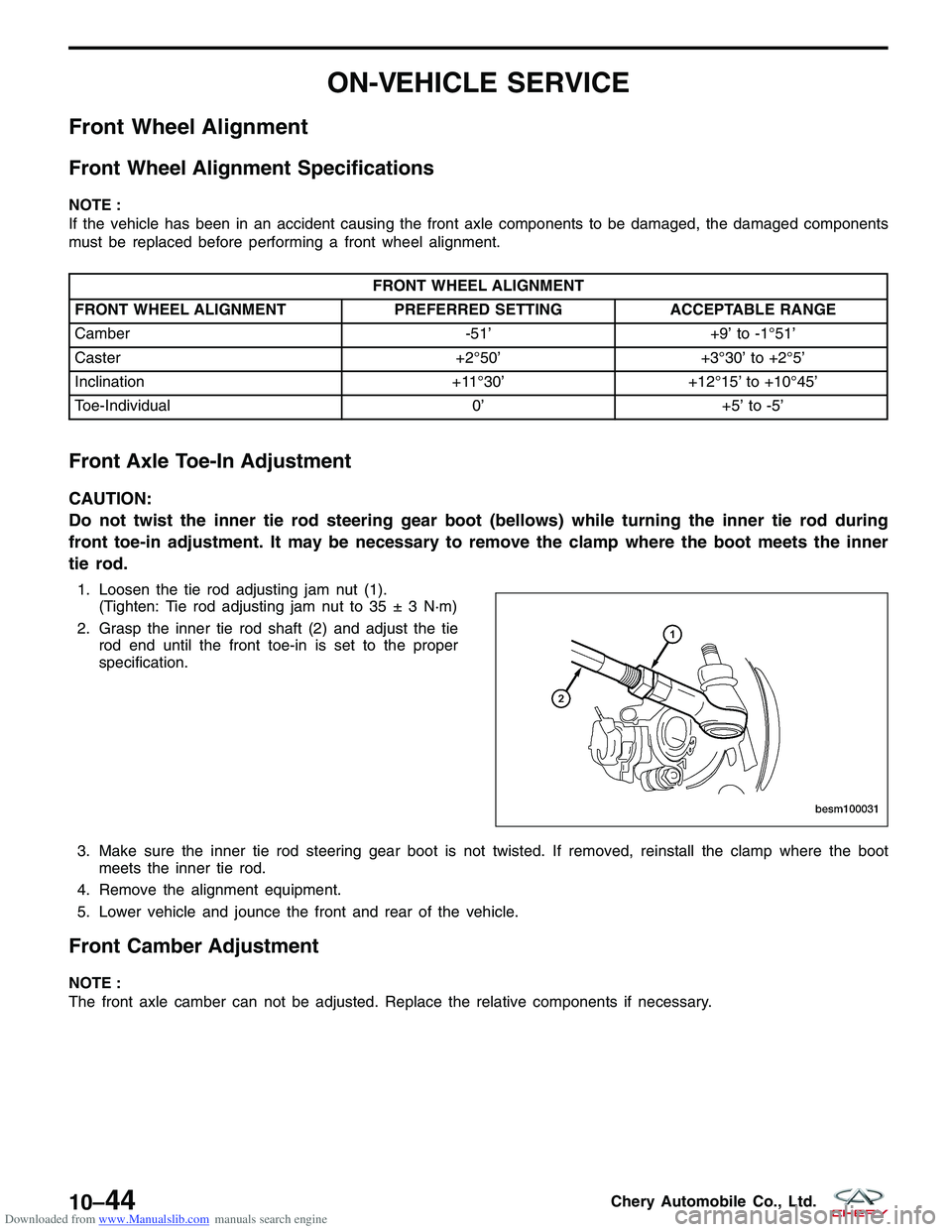
1. Loosen the tie rod adjusting jam nut (1).
(Tighten: Tie rod adjusting jam nut to 35 ± 3 N·m)
2. Grasp the inner tie rod shaft (2) and adjust the tie rod end until the front toe-in is set to the proper
specification.
3. Make sure the inner tie rod steering gear boot is not twisted. If removed, reinstall the clamp where the boot meets the inner tie rod.
4. Remove the alignment equipment.
5. Lower vehicle and jounce the front and rear of the vehicle.
Front Camber Adjustment
NOTE :
The front axle camber can not be adjusted. Replace the relative components if necessary.
BESM100031
10–44Chery Automobile Co., Ltd.
Page 1346 of 1903
Downloaded from www.Manualslib.com manuals search engine Rear Wheel Alignment
Rear Wheel Alignment Specifications
NOTE :
If the vehicle has been in an accident causing the rear axle components to be damaged, the damaged components
must be replaced before performing a rear wheel alignment.
REAR WHEEL ALIGNMENT
REAR WHEEL ALIGNMENT PREFERRED SETTINGACCEPTABLE RANGE
Camber -54’-24’ to -1°24’
Toe-Individual -5’+5’ to -15’
Rear Axle Toe-In Adjustment
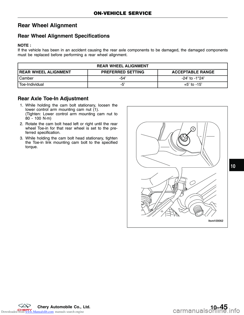
1. While holding the cam bolt stationary, loosen the
lower control arm mounting cam nut (1).
(Tighten: Lower control arm mounting cam nut to
80 - 100 N·m)
2. Rotate the cam bolt head left or right until the rear wheel Toe-in for that rear wheel is set to the pre-
ferred specification.
3. While holding the cam bolt head stationary, tighten the Toe-in link mounting cam bolt to the specified
torque.
ON-VEHICLE SERVICE
BESM100031
10
10–45Chery Automobile Co., Ltd.
Page 1347 of 1903
Downloaded from www.Manualslib.com manuals search engine Rear Camber Adjustment
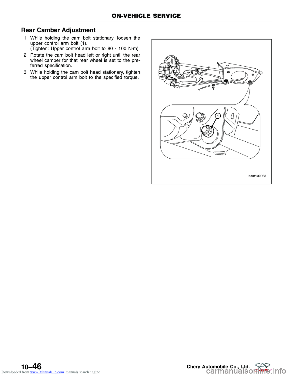
1. While holding the cam bolt stationary, loosen theupper control arm bolt (1).
(Tighten: Upper control arm bolt to 80 - 100 N·m)
2. Rotate the cam bolt head left or right until the rear wheel camber for that rear wheel is set to the pre-
ferred specification.
3. While holding the cam bolt head stationary, tighten the upper control arm bolt to the specified torque.
ON-VEHICLE SERVICE
BESM100031
10–46Chery Automobile Co., Ltd.
Page 1348 of 1903
Downloaded from www.Manualslib.com manuals search engine WHEELS AND TIRES
GENERAL INFORMATION10-48
Description 10-48
Operation 10-48
Specifications 10-48
DIAGNOSIS & TESTING10-50
Vehicle Inspection 10-50
Tire and Wheel Vibration 10-50
Tire Wear Patterns 10-50
Wheel Out-Of-Round Inspection 10-50
ON-VEHICLE SERVICE10-51
Tire Repair 10-51
Description 10-51 Replacement Procedure 10-51
Repair Procedure 10-51
Wheel Assembly 10-52
Description 10-52
Removal & Installation 10-52
Wheel Balance 10-52
Description 10-52
Wheel Balance Procedure 10-53
Tire Rotation 10-53
Description 10-53
Non-Directional Tires 10-54
Directional Tires 10-54
10
10–47Chery Automobile Co., Ltd.
Page 1349 of 1903
Downloaded from www.Manualslib.com manuals search engine GENERAL INFORMATION
Description
Tires are designed and engineered for each specific vehicle. They provide the best overall performance for normal
operation. The ride and handling characteristics match the vehicle’s requirements. With proper care they will give
excellent reliability, traction, skid resistance, and tread life.
Tire Identification
•Tire type, size, load index and speed rating are encoded in the letters and numbers imprinted on the side wall
of the tire.
Spare Tire
• A full size spare tire and wheel assembly is standard equipment on this vehicle. The original tire should be
repaired or replaced at the first opportunity, then reinstalled.
Operation
Driving habits have more effect on tire life than any other factor. Careful drivers will obtain, in most cases, much
greater mileage than severe use or careless drivers. A few of the driving habits which will shorten the life of any tire
are:
•Rapid acceleration
• Severe application of brakes
• High-speed driving
• Taking turns at excessive speeds
• Striking curbs and other obstacles
• Operating vehicle with over or under inflated tire pressures
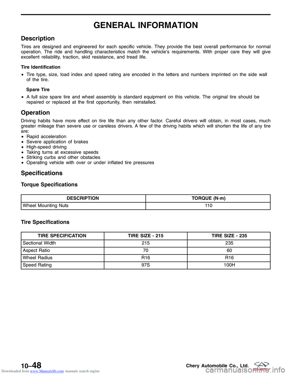
Specifications
Torque Specifications
DESCRIPTION TORQUE (N·m)
Wheel Mounting Nuts 110
Tire Specifications
TIRE SPECIFICATIONTIRE SIZE - 215TIRE SIZE - 235
Sectional Width 215235
Aspect Ratio 7060
Wheel Radius R16R16
Speed Rating 97S100H
10–48Chery Automobile Co., Ltd.
Page 1350 of 1903
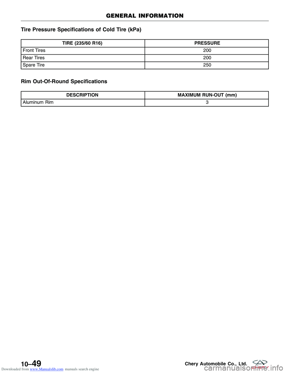
Downloaded from www.Manualslib.com manuals search engine Tire Pressure Specifications of Cold Tire (kPa)
TIRE (235/60 R16)PRESSURE
Front Tires 200
Rear Tires 200
Spare Tire 250
Rim Out-Of-Round Specifications
DESCRIPTIONMAXIMUM RUN-OUT (mm)
Aluminum Rim 3
GENERAL INFORMATION
10–49Chery Automobile Co., Ltd.