CHERY TIGGO 2009 Service Repair Manual
Manufacturer: CHERY, Model Year: 2009, Model line: TIGGO, Model: CHERY TIGGO 2009Pages: 1903, PDF Size: 33.38 MB
Page 1311 of 1903
Downloaded from www.Manualslib.com manuals search engine 1. Raise and support the vehicle.
2. Remove the wheel mounting nuts and the wheel assembly.(Tighten: Wheel mounting nuts to 110 N·m)
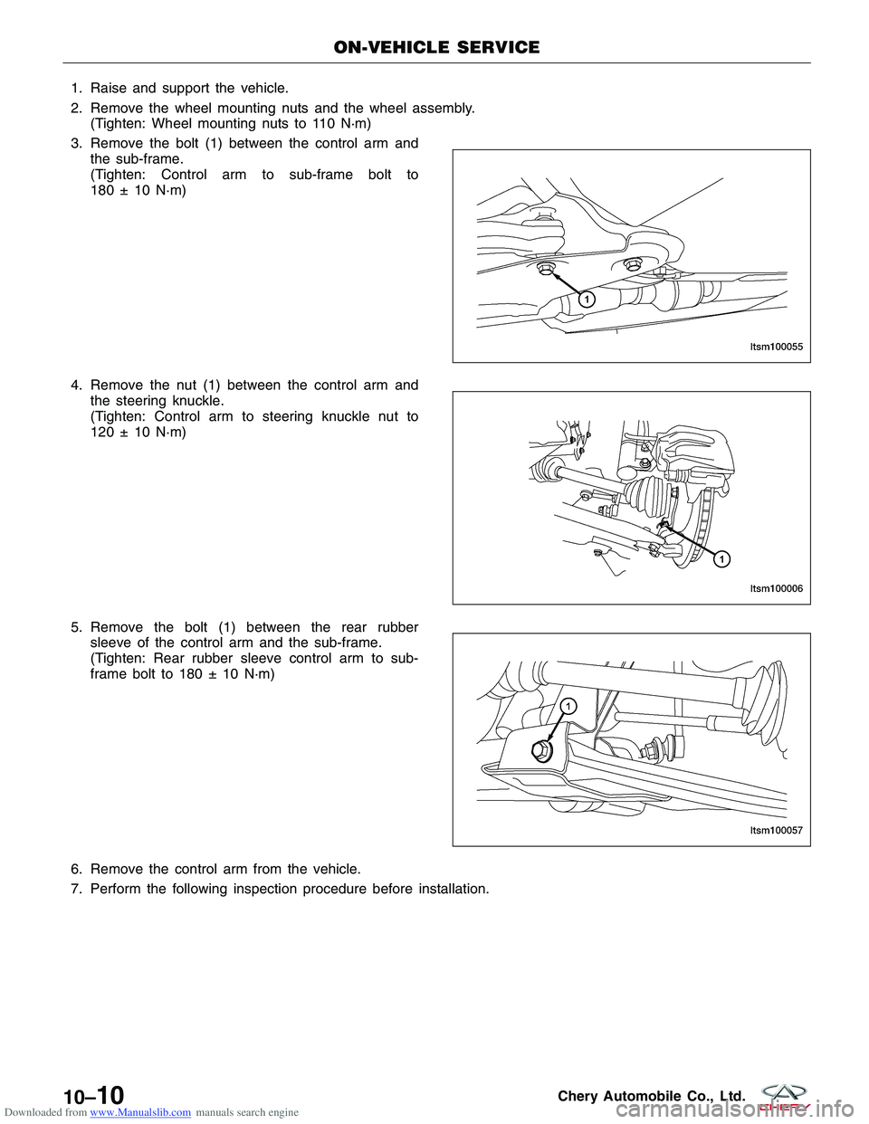
3. Remove the bolt (1) between the control arm and the sub-frame.
(Tighten: Control arm to sub-frame bolt to
180 ± 10 N·m)
4. Remove the nut (1) between the control arm and the steering knuckle.
(Tighten: Control arm to steering knuckle nut to
120 ± 10 N·m)
5. Remove the bolt (1) between the rear rubber sleeve of the control arm and the sub-frame.
(Tighten: Rear rubber sleeve control arm to sub-
frame bolt to 180 ± 10 N·m)
6. Remove the control arm from the vehicle.
7. Perform the following inspection procedure before installation.
ON-VEHICLE SERVICE
LTSM100055
LTSM100006
LTSM100057
10–10Chery Automobile Co., Ltd.
Page 1312 of 1903
Downloaded from www.Manualslib.com manuals search engine Inspection
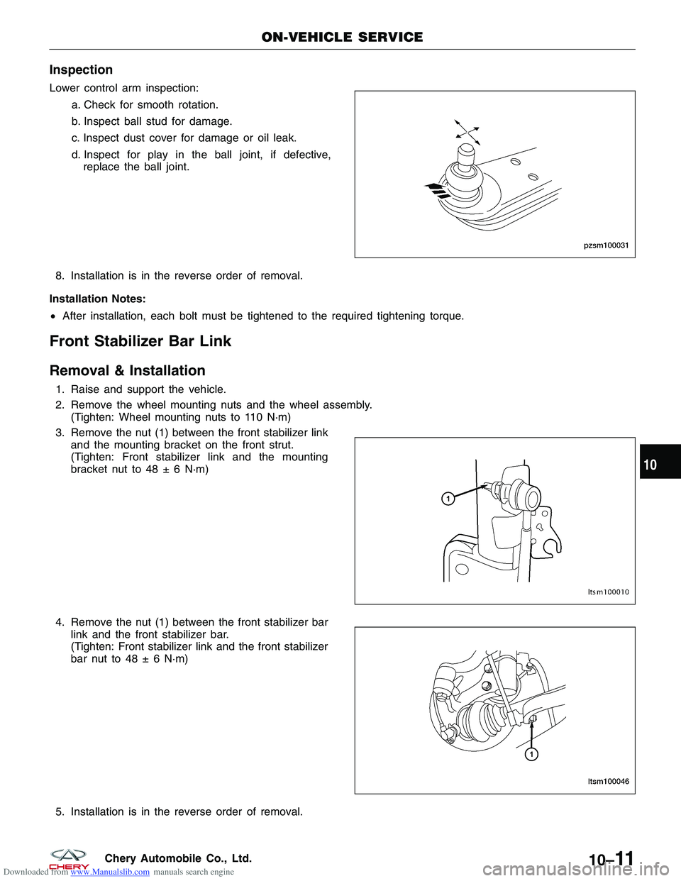
Lower control arm inspection:a. Check for smooth rotation.
b. Inspect ball stud for damage.
c. Inspect dust cover for damage or oil leak.
d. Inspect for play in the ball joint, if defective,
replace the ball joint.
8. Installation is in the reverse order of removal.
Installation Notes:
• After installation, each bolt must be tightened to the required tightening torque.
Front Stabilizer Bar Link
Removal & Installation
1. Raise and support the vehicle.
2. Remove the wheel mounting nuts and the wheel assembly.
(Tighten: Wheel mounting nuts to 110 N·m)
3. Remove the nut (1) between the front stabilizer link and the mounting bracket on the front strut.
(Tighten: Front stabilizer link and the mounting
bracket nut to 48 ± 6 N·m)
4. Remove the nut (1) between the front stabilizer bar link and the front stabilizer bar.
(Tighten: Front stabilizer link and the front stabilizer
bar nut to 48 ± 6 N·m)
5. Installation is in the reverse order of removal.
ON-VEHICLE SERVICE
PZSM100031
LTSM100010
LTSM100046
10
10–11Chery Automobile Co., Ltd.
Page 1313 of 1903
Downloaded from www.Manualslib.com manuals search engine Installation Notes:
•After installation, each bolt must be tightened to the required tightening torque.
Front Stabilizer Bar
Removal & Installation
1. Raise and support the vehicle.
2. Remove the wheel mounting nuts and the wheel assembly.
(Tighten: Wheel mounting nuts to 110 N·m)
3. Remove the front stabilizer bar link (See Front Stabilizer Bar Link Removal & Installation in Section 10 Suspen- sion).
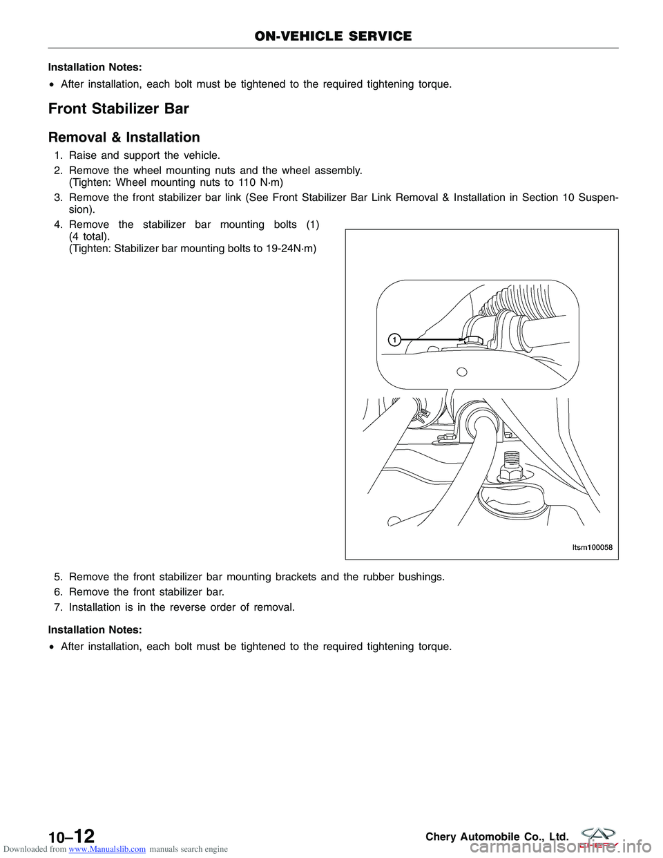
4. Remove the stabilizer bar mounting bolts (1) (4 total).
(Tighten: Stabilizer bar mounting bolts to 19-24N·m)
19 - 24 N·m)
5. Remove the front stabilizer bar mounting brackets and the rubber bushings.
6. Remove the front stabilizer bar.
7. Installation is in the reverse order of removal.
Installation Notes:
• After installation, each bolt must be tightened to the required tightening torque.
ON-VEHICLE SERVICE
LTSM100058
10–12Chery Automobile Co., Ltd.
Page 1314 of 1903
Downloaded from www.Manualslib.com manuals search engine Front Strut Assembly
Description
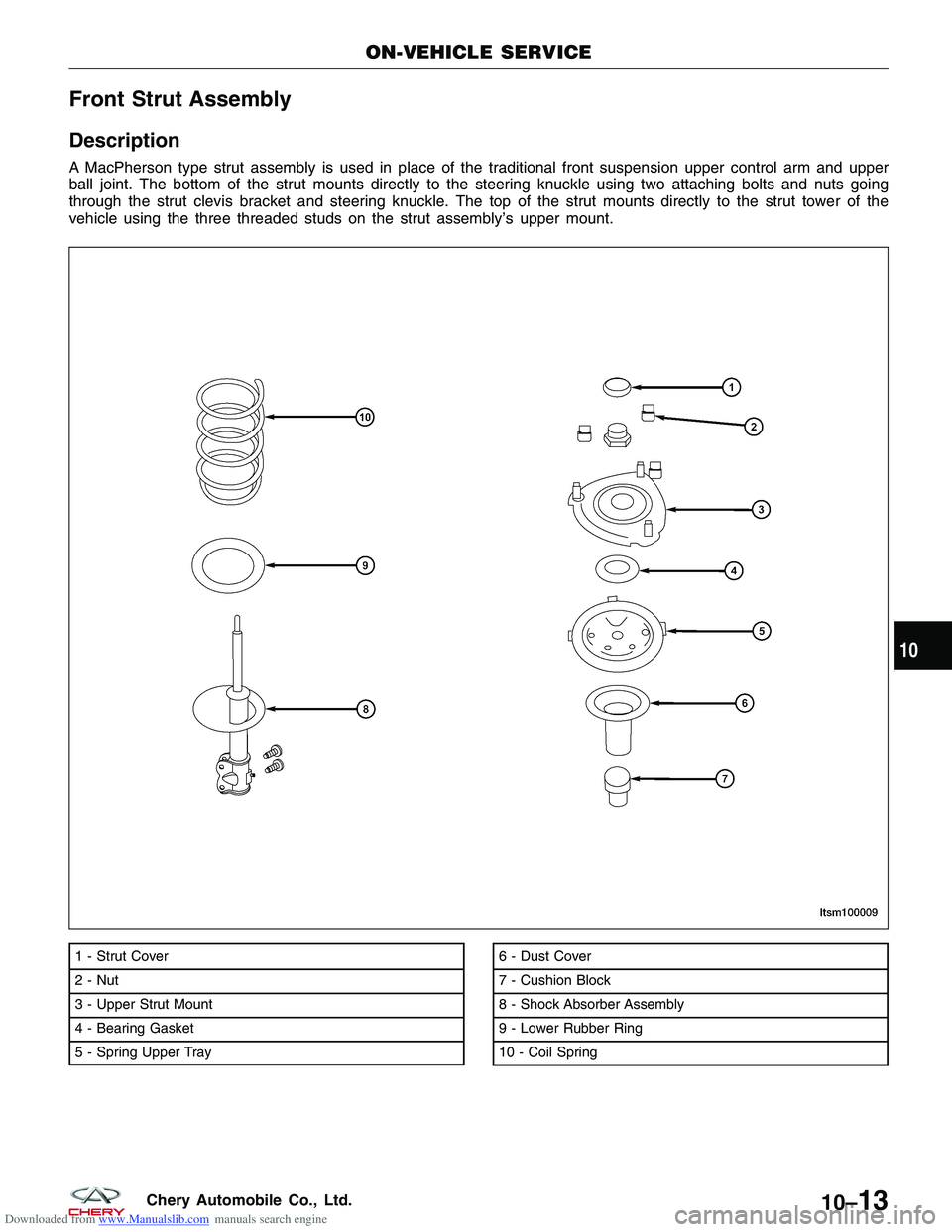
A MacPherson type strut assembly is used in place of the traditional front suspension upper control arm and upper
ball joint. The bottom of the strut mounts directly to the steering knuckle using two attaching bolts and nuts going
through the strut clevis bracket and steering knuckle. The top of the strut mounts directly to the strut tower of the
vehicle using the three threaded studs on the strut assembly’s upper mount.
1 - Strut Cover
2 - Nut
3 - Upper Strut Mount
4 - Bearing Gasket
5 - Spring Upper Tray6 - Dust Cover
7 - Cushion Block
8 - Shock Absorber Assembly
9 - Lower Rubber Ring
10 - Coil Spring
ON-VEHICLE SERVICE
LTSM100009
10
10–13Chery Automobile Co., Ltd.
Page 1315 of 1903
Downloaded from www.Manualslib.com manuals search engine Operation
The strut assembly cushions the ride of the vehicle, controlling vibration, jounce and rebound of the suspension. The
coil spring controls ride quality and maintains proper ride height. The spring isolators isolate the coil spring at the top
and bottom from coming into metal-to-metal contact with the upper mounting seat and the strut. The strut dampens
jounce and rebound motions of the coil spring and suspension.
Diagnosis & Testing
Before removing the front strut, perform the following to test the front strut functionality:
•Adjust the tire pressure to all tires to proper specifications.
• Push and shake the front of the vehicle three or four times with identical force every time
• During the pushing and recoiling, the resistance and recoil times of the vehicle should be equal.
• If the strut (shock absorber) functions properly, the vehicle will recoil several times and then stop recoiling after
the pushing force is removed.
Removal & Installation
1. Raise and support the vehicle.
2. Remove the wheel mounting nuts and the wheel assembly.
(Tighten: Wheel mounting nuts to 110 N·m)
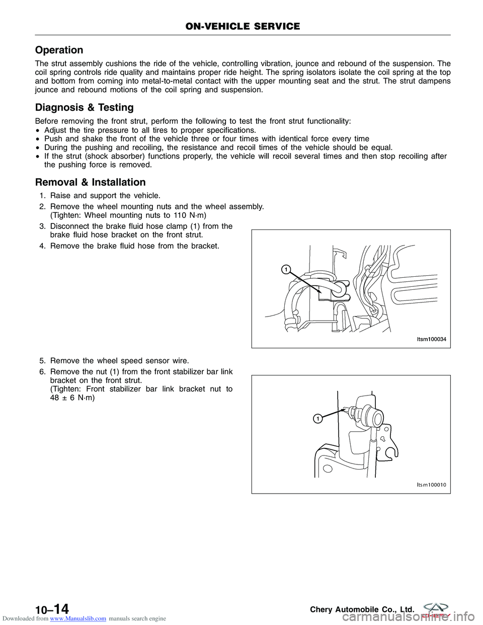
3. Disconnect the brake fluid hose clamp (1) from the brake fluid hose bracket on the front strut.
4. Remove the brake fluid hose from the bracket.
5. Remove the wheel speed sensor wire.
6. Remove the nut (1) from the front stabilizer bar link bracket on the front strut.
(Tighten: Front stabilizer bar link bracket nut to
48 ± 6 N·m)
ON-VEHICLE SERVICE
LTSM100034
LTSM100010
10–14Chery Automobile Co., Ltd.
Page 1316 of 1903
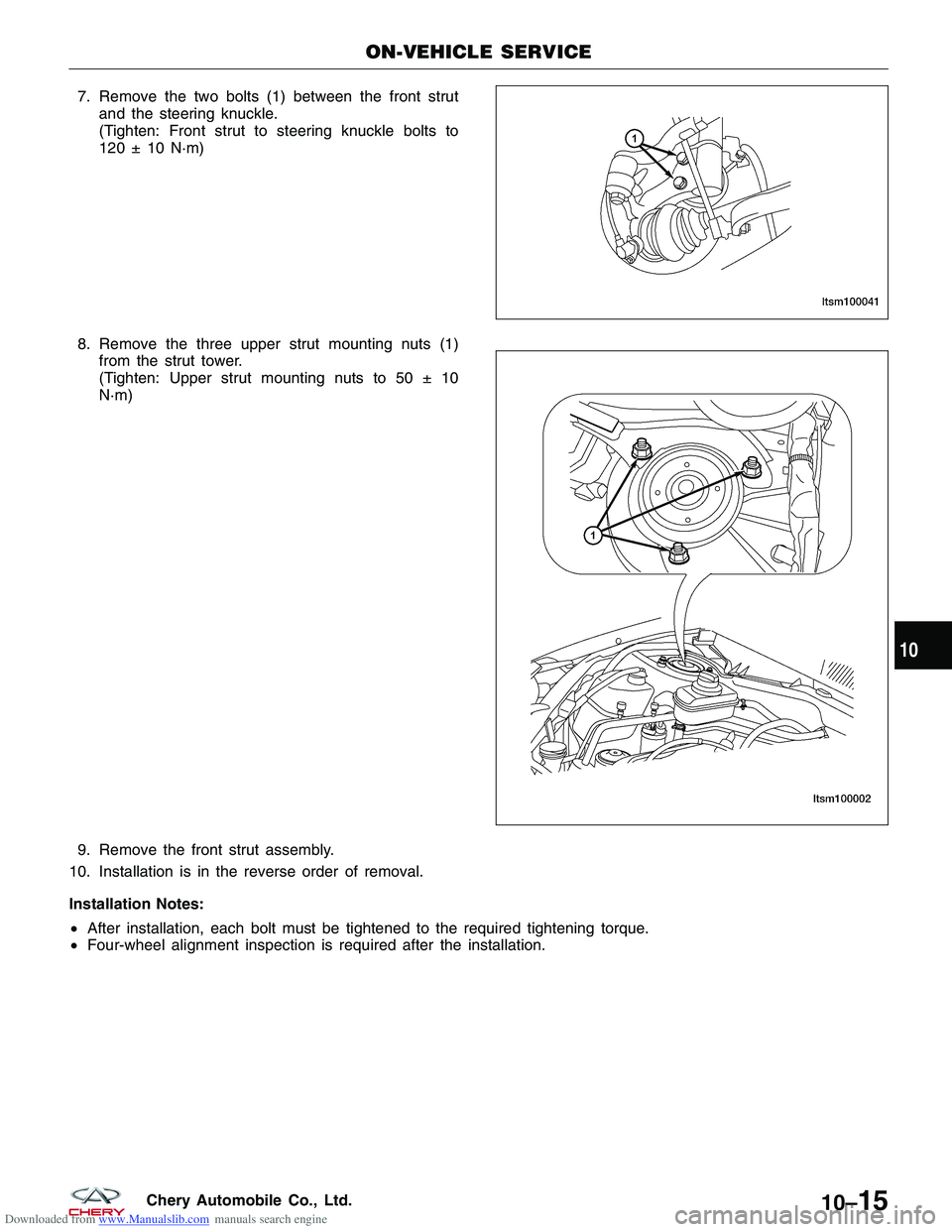
Downloaded from www.Manualslib.com manuals search engine 7. Remove the two bolts (1) between the front strutand the steering knuckle.
(Tighten: Front strut to steering knuckle bolts to
120 ± 10 N·m)
8. Remove the three upper strut mounting nuts (1) from the strut tower.
(Tighten: Upper strut mounting nuts to 50 ± 10
N·m)
9. Remove the front strut assembly.
10. Installation is in the reverse order of removal.
Installation Notes:
• After installation, each bolt must be tightened to the required tightening torque.
• Four-wheel alignment inspection is required after the installation.
ON-VEHICLE SERVICE
LTSM100041
LTSM100002
10
10–15Chery Automobile Co., Ltd.
Page 1317 of 1903
Downloaded from www.Manualslib.com manuals search engine Front Coil Spring
Description
A coil-over front strut assembly supports each front coil spring. The top of the strut assembly mounts to the strut
tower.
Operation
Coil springs are designed to store energy and subsequently release it and to absorb shock and maintain a force
between contacting surfaces. Coil springs are rated for specific vehicle applications.
NOTE :
Each component is serviced by removing the strut assembly from the vehicle and disassembling it. Coil springs are
rated separately for each corner or side of the vehicle depending on optional equipment and type of vehicle service.
If a coil spring requires replacement, be sure that it is replaced with a spring meeting the correct load rating for the
vehicle and its specific options.
Removal & Installation
CAUTION:
At no time when servicing a vehicle can a sheet metal screw, bolt or other metal fastener be
installed into the strut tower to take the place of an original plastic clamp. Also, do not drill holes
into the front strut tower for the installation of any metal fasteners into the strut tower area indi-
cated.
1. Raise and support the vehicle.
2. Remove the front strut assembly (See Front Strut Removal & Installation in Section 10 Suspension).
WARNING!
Do not remove the strut rod nut before the coil spring is properly compressed. The coil spring is held under
pressure. The coil spring must be compressed, removing spring tension from the upper mount and bearing,
before the strut rod nut is removed.
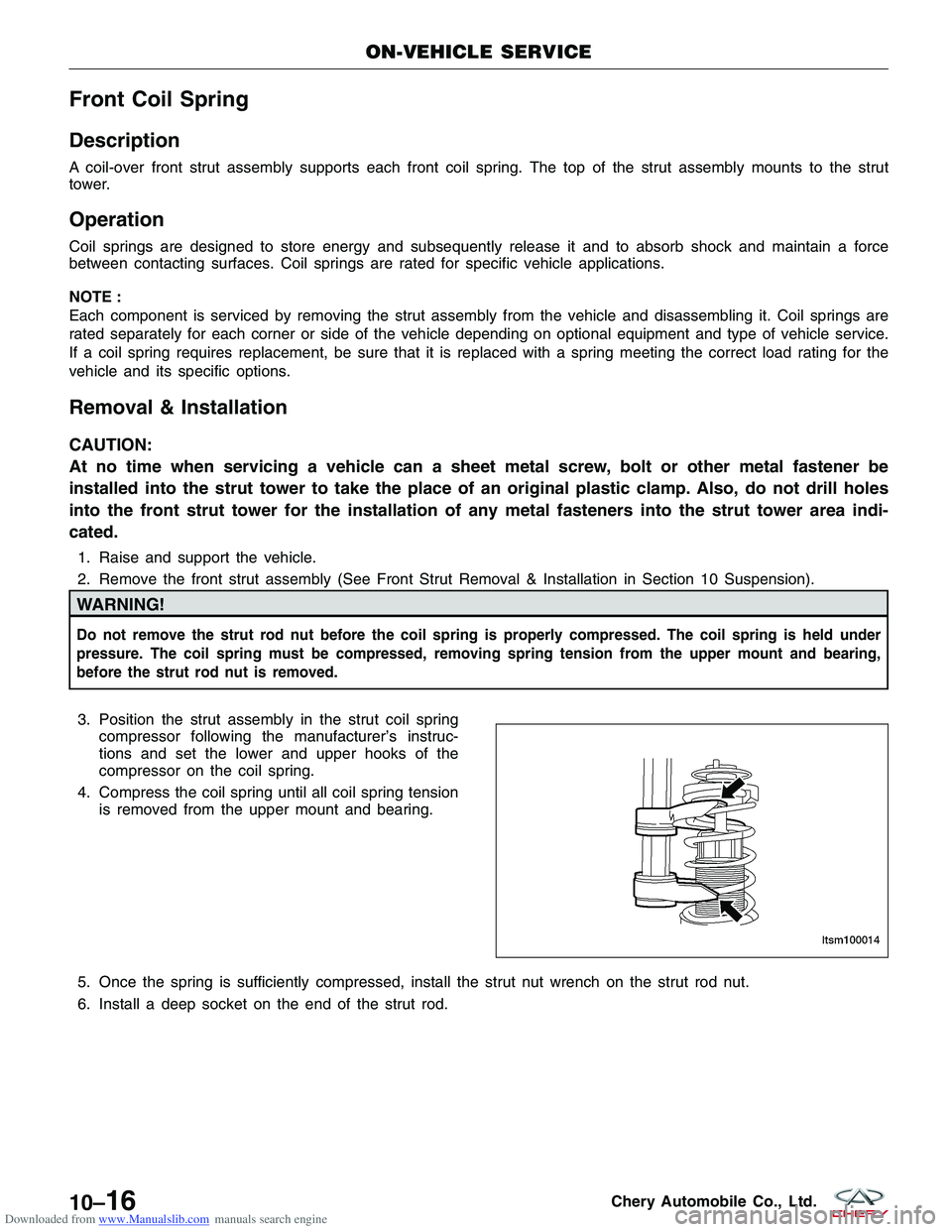
3. Position the strut assembly in the strut coil springcompressor following the manufacturer’s instruc-
tions and set the lower and upper hooks of the
compressor on the coil spring.
4. Compress the coil spring until all coil spring tension is removed from the upper mount and bearing.
5. Once the spring is sufficiently compressed, install the strut nut wrench on the strut rod nut.
6. Install a deep socket on the end of the strut rod.
ON-VEHICLE SERVICE
LTSM100014
10–16Chery Automobile Co., Ltd.
Page 1318 of 1903
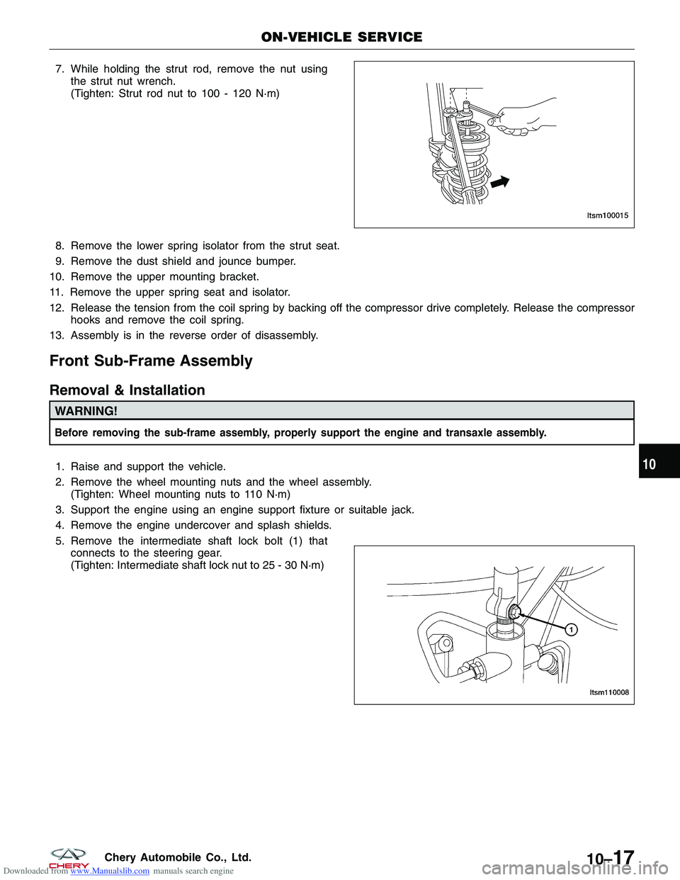
Downloaded from www.Manualslib.com manuals search engine 7. While holding the strut rod, remove the nut usingthe strut nut wrench.
(Tighten: Strut rod nut to 100 - 120 N·m)
8. Remove the lower spring isolator from the strut seat.
9. Remove the dust shield and jounce bumper.
10. Remove the upper mounting bracket.
11. Remove the upper spring seat and isolator.
12. Release the tension from the coil spring by backing off the compressor drive completely. Release the compressor hooks and remove the coil spring.
13. Assembly is in the reverse order of disassembly.
Front Sub-Frame Assembly
Removal & Installation
WARNING!
Before removing the sub-frame assembly, properly support the engine and transaxle assembly.
1. Raise and support the vehicle.
2. Remove the wheel mounting nuts and the wheel assembly. (Tighten: Wheel mounting nuts to 110 N·m)
3. Support the engine using an engine support fixture or suitable jack.
4. Remove the engine undercover and splash shields.
5. Remove the intermediate shaft lock bolt (1) that connects to the steering gear.
(Tighten: Intermediate shaft lock nut to 25 - 30 N·m)
ON-VEHICLE SERVICE
LTSM100015
LTSM110008
10
10–17Chery Automobile Co., Ltd.
Page 1319 of 1903

Downloaded from www.Manualslib.com manuals search engine 6. Remove the nut (1) between the control arm andthe steering knuckle.
(Tighten: Control arm to steering knuckle nut to
120 ± 10 N·m)
7. Remove the wheel speed sensor mounting bolt (1). (Tighten: Wheel speed sensor mounting bolt to 10
± 1 N·m)
8. Remove the wheel speed sensor and set it aside.
9. Remove the left and right front stabilizer bar links (See Front Stabilizer Bar Link Removal & Installation in Sec- tion 10 Suspension).
10. Remove the nut (1) attaching the outer tie rod ends to the steering knuckle on each side of the steering
rack.
(Tighten: Outer tie rod end nut to 35 N·m)
11. Remove the exhaust pipe assembly mounting bolts (1).
(Tighten: Exhaust pipe assembly mounting bolts to
25 ± 3 N·m)
ON-VEHICLE SERVICE
LTSM100006
LTSM100045
LTSM110034 VISM110016
10–18Chery Automobile Co., Ltd.
Page 1320 of 1903
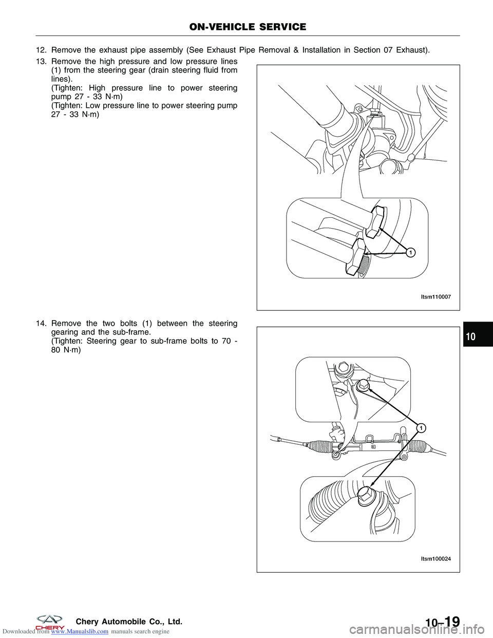
Downloaded from www.Manualslib.com manuals search engine 12. Remove the exhaust pipe assembly (See Exhaust Pipe Removal & Installation in Section 07 Exhaust).
13. Remove the high pressure and low pressure lines(1) from the steering gear (drain steering fluid from
lines).
(Tighten: High pressure line to power steering
pump 27 - 33 N·m)
(Tighten: Low pressure line to power steering pump
27 - 33 N·m)
14. Remove the two bolts (1) between the steering gearing and the sub-frame.
(Tighten: Steering gear to sub-frame bolts to 70 -
80 N·m)
ON-VEHICLE SERVICE
LTSM110007
LTSM100024
10
10–19Chery Automobile Co., Ltd.