CHERY TIGGO 2009 Service Repair Manual
Manufacturer: CHERY, Model Year: 2009,
Model line: TIGGO,
Model: CHERY TIGGO 2009
Pages: 1903, PDF Size: 33.38 MB
CHERY TIGGO 2009 Service Repair Manual
TIGGO 2009
CHERY
CHERY
https://www.carmanualsonline.info/img/53/56852/w960_56852-0.png
CHERY TIGGO 2009 Service Repair Manual
Trending: airbag, change wheel, USB, parking brake, service interval, air conditioning, climate control
Page 1621 of 1903
Downloaded from www.Manualslib.com manuals search engine 14. Remove three door lock assembly retaining bolts.(Tighten: Door lock assembly retaining bolts to9±1N·m)
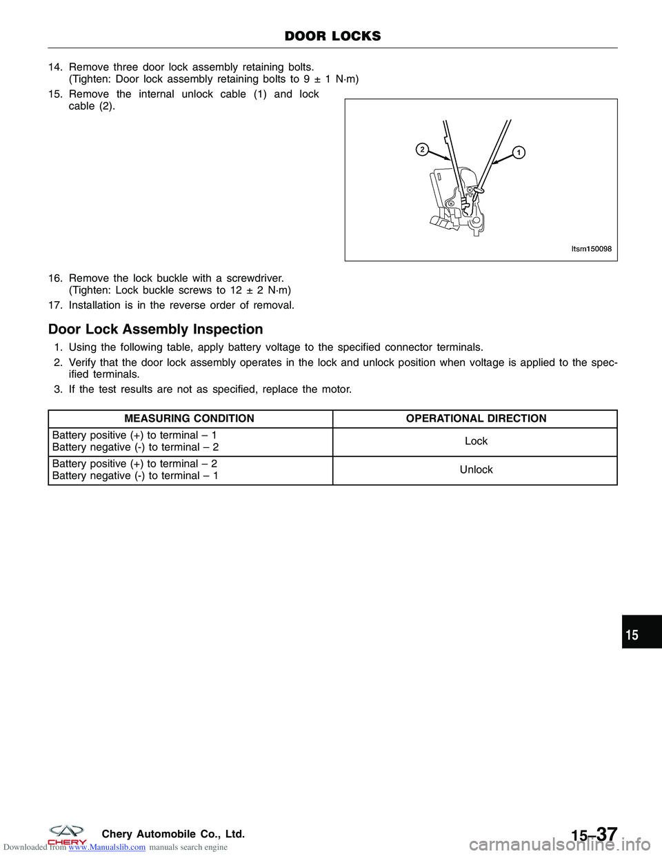
15. Remove the internal unlock cable (1) and lock cable (2).
16. Remove the lock buckle with a screwdriver. (Tighten: Lock buckle screws to 12 ± 2 N·m)
17. Installation is in the reverse order of removal.
Door Lock Assembly Inspection
1. Using the following table, apply battery voltage to the specified connector terminals.
2. Verify that the door lock assembly operates in the lock and unlock position when voltage is applied to the spec- ified terminals.
3. If the test results are not as specified, replace the motor.
MEASURING CONDITION OPERATIONAL DIRECTION
Battery positive (+) to terminal – 1
Battery negative (-) to terminal – 2 Lock
Battery positive (+) to terminal – 2
Battery negative (-) to terminal – 1 Unlock
DOOR LOCKS
LTSM150098
15
15–37Chery Automobile Co., Ltd.
Page 1622 of 1903
Downloaded from www.Manualslib.com manuals search engine BODY CONTROL MODULE - BCM
Description
The Body Control Module (BCM) is located behind the glove box. The BCM controls many electrical components and
systems for the vehicle electrical system. The BCM is the primary hub that controls functions such as internal and
external lighting, power windows and power door locks.
Operation
The Body Control Module (BCM) uses hard wired inputs from various sensors and switches. The sensors and
switches are located throughout the vehicle.
The following components are inputs to the BCM:
•Key switch
• Rear defroster switch
• Hazard lamp switch
• Power window switches
• Power door lock switches
• Seat belt switch
• Vehicle speed
• Door ajar switches
• Turn signal switch
The following components are outputs from the BCM:
• Key lamp
• Stop lamp relay
• Rear defroster grid
• Courtesy lamps
• Power window motor
• Power door lock motor
• Turn signal lamps
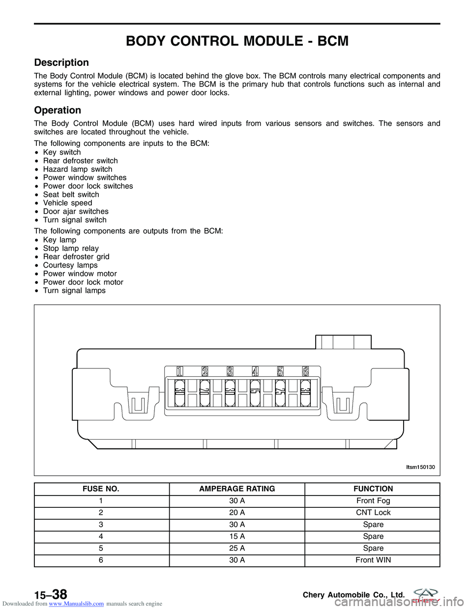
FUSE NO. AMPERAGE RATING FUNCTION
1 30 AFront Fog
2 20 ACNT Lock
3 30 A Spare
4 15 A Spare
5 25 A Spare
6 30 AFront WIN
LTSM150130
15–38Chery Automobile Co., Ltd.
Page 1623 of 1903
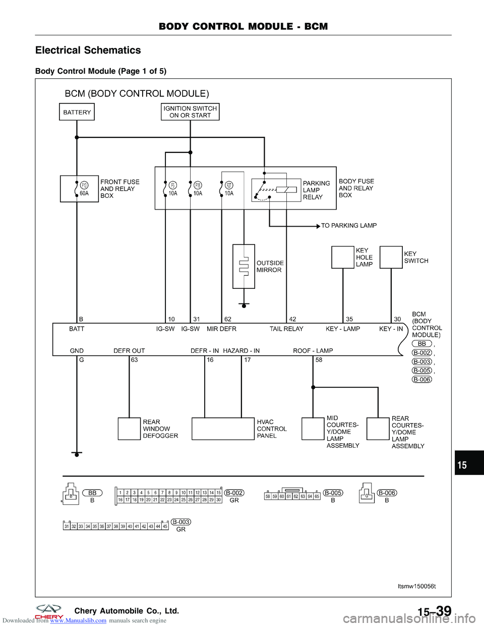
Downloaded from www.Manualslib.com manuals search engine Electrical Schematics
Body Control Module (Page 1 of 5)
BODY CONTROL MODULE - BCM
LTSMW150056T
15
15–39Chery Automobile Co., Ltd.
Page 1624 of 1903
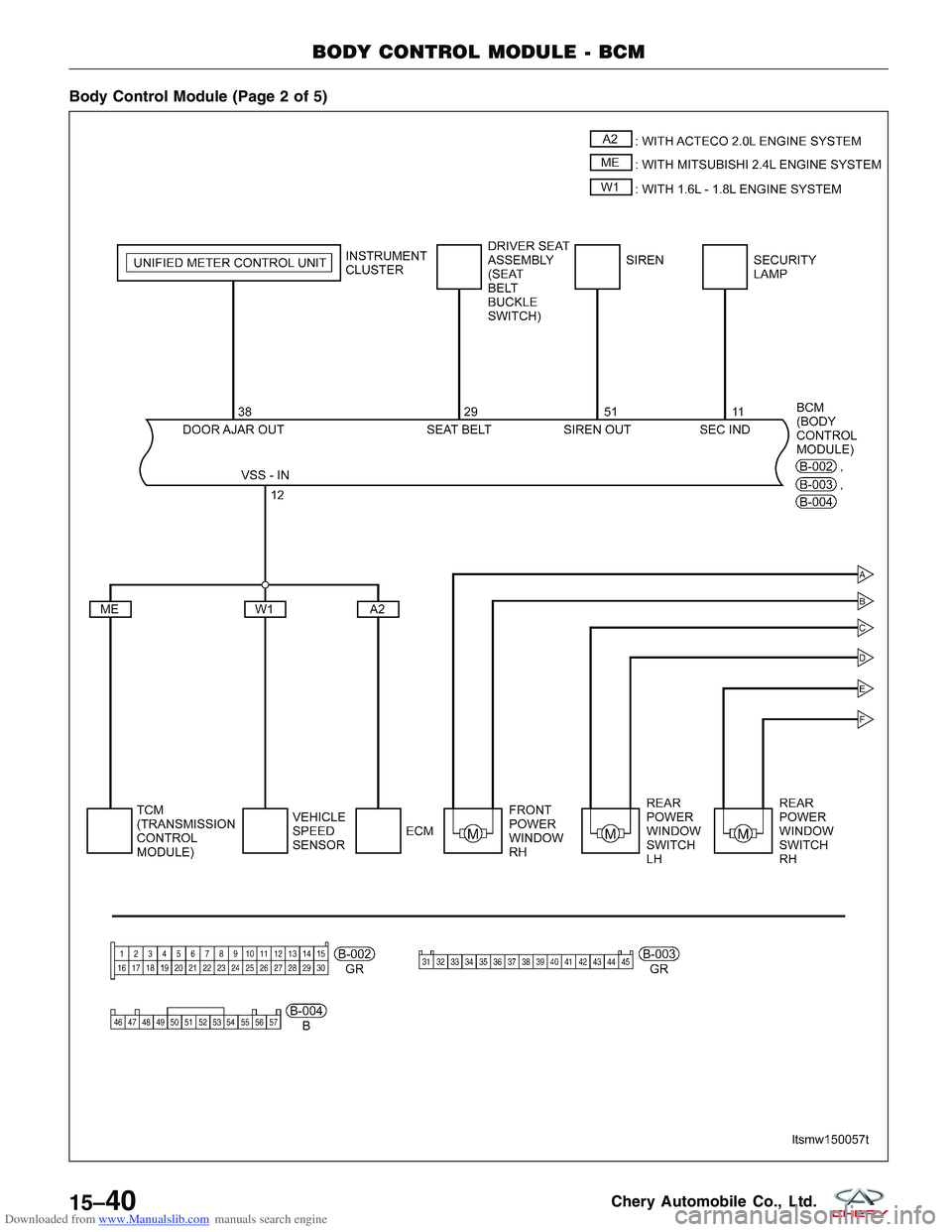
Downloaded from www.Manualslib.com manuals search engine Body Control Module (Page 2 of 5)
BODY CONTROL MODULE - BCM
LTSMW150057T
15–40Chery Automobile Co., Ltd.
Page 1625 of 1903
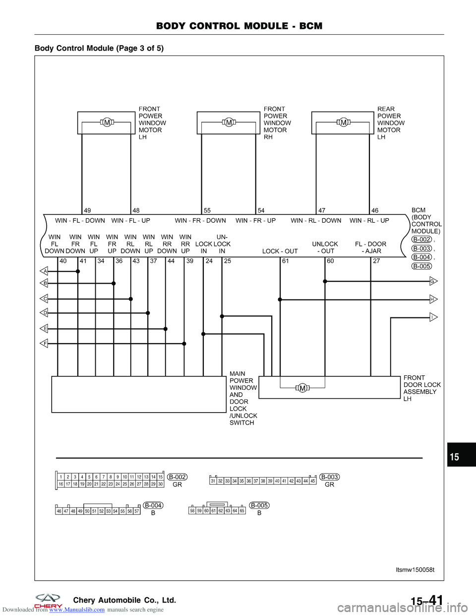
Downloaded from www.Manualslib.com manuals search engine Body Control Module (Page 3 of 5)
BODY CONTROL MODULE - BCM
LTSMW150058T
15
15–41Chery Automobile Co., Ltd.
Page 1626 of 1903
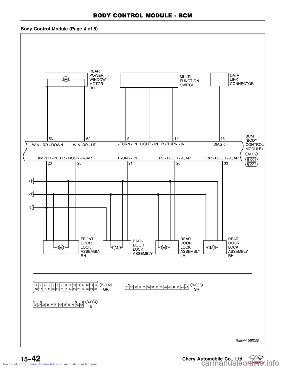
Downloaded from www.Manualslib.com manuals search engine Body Control Module (Page 4 of 5)
BODY CONTROL MODULE - BCM
LTSMW150059T
15–42Chery Automobile Co., Ltd.
Page 1627 of 1903
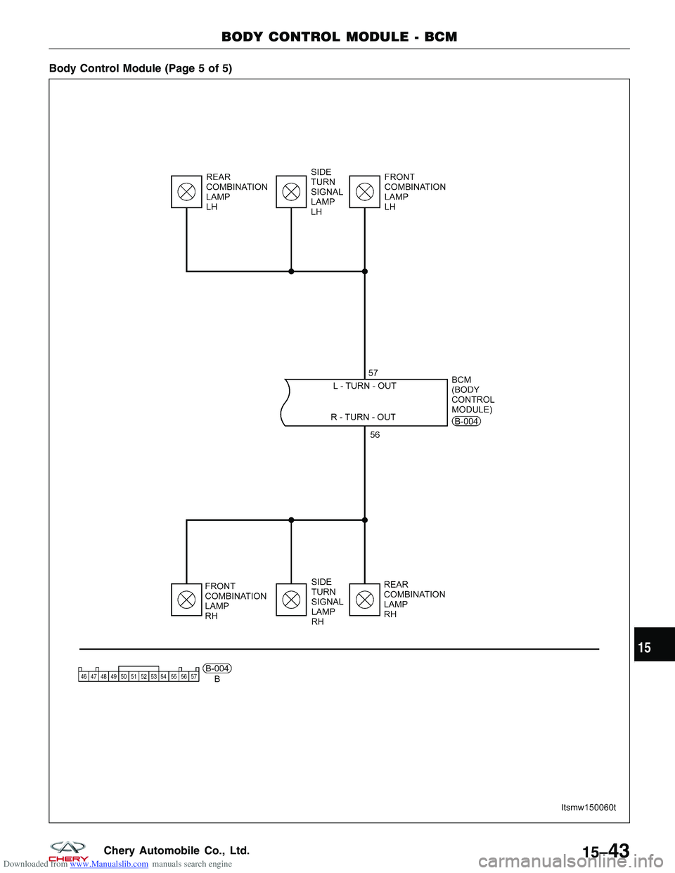
Downloaded from www.Manualslib.com manuals search engine Body Control Module (Page 5 of 5)
BODY CONTROL MODULE - BCM
LTSMW150060T
15
15–43Chery Automobile Co., Ltd.
Page 1628 of 1903
Downloaded from www.Manualslib.com manuals search engine ON-VEHICLE SERVICE
Body Control Module (BCM)
Removal & Installation
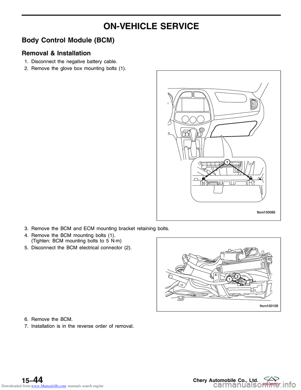
1. Disconnect the negative battery cable.
2. Remove the glove box mounting bolts (1).
3. Remove the BCM and ECM mounting bracket retaining bolts.
4. Remove the BCM mounting bolts (1).(Tighten: BCM mounting bolts to 5 N·m)
5. Disconnect the BCM electrical connector (2).
6. Remove the BCM.
7. Installation is in the reverse order of removal.
LTSM150086
LTSM150109
15–44Chery Automobile Co., Ltd.
Page 1629 of 1903
Downloaded from www.Manualslib.com manuals search engine INSTRUMENT PANEL
Removal & Installation
1. Remove the steering wheel (See Steering Wheel Removal & Installation in Section 11 Steering).
2. Remove the multi-function switch and the wiper switch.
3. Remove the instrument cluster (See Instrument Cluster Removal & Installation in Section 15 Body & Accesso-ries).
4. Remove the radio (See Radio Removal & Installation in Section 15 Body & Accessories).
5. Remove the HVAC control panel (See HVAC Control Panel Removal & Installation in Section 13 Heating & Air Conditioning).
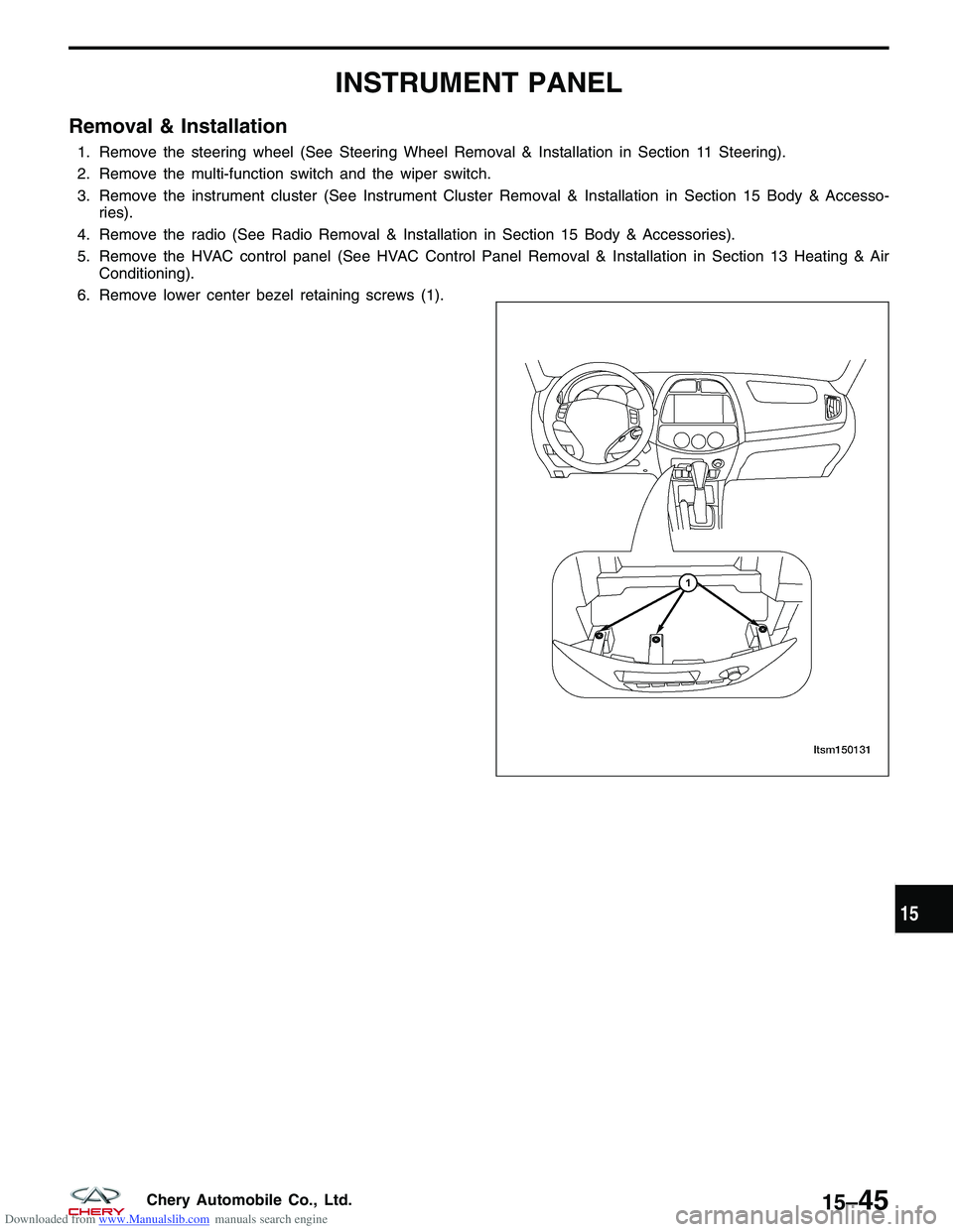
6. Remove lower center bezel retaining screws (1).
LTSM150131
15
15–45Chery Automobile Co., Ltd.
Page 1630 of 1903
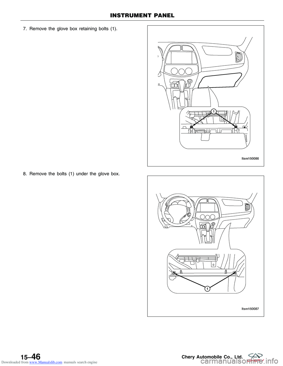
Downloaded from www.Manualslib.com manuals search engine 7. Remove the glove box retaining bolts (1).
8. Remove the bolts (1) under the glove box.
INSTRUMENT PANEL
LTSM150086
LTSM150087
15–46Chery Automobile Co., Ltd.
Trending: fuel cap, fog light, battery replacement, fuse diagram, fold seats, airbag off, seat adjustment
