CHERY TIGGO 2009 Service Repair Manual
Manufacturer: CHERY, Model Year: 2009, Model line: TIGGO, Model: CHERY TIGGO 2009Pages: 1903, PDF Size: 33.38 MB
Page 1581 of 1903
Downloaded from www.Manualslib.com manuals search engine ON-VEHICLE SERVICE
Front Seat Belt and Pre-Tensioner
Removal & Installation
1. Turn the ignition off.
2. Disconnect the negative battery cable.
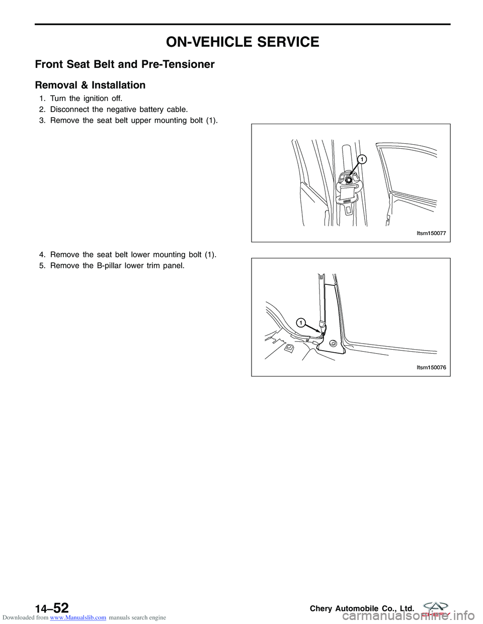
3. Remove the seat belt upper mounting bolt (1).
4. Remove the seat belt lower mounting bolt (1).
5. Remove the B-pillar lower trim panel.
LTSM150077
LTSM150076
14–52Chery Automobile Co., Ltd.
Page 1582 of 1903
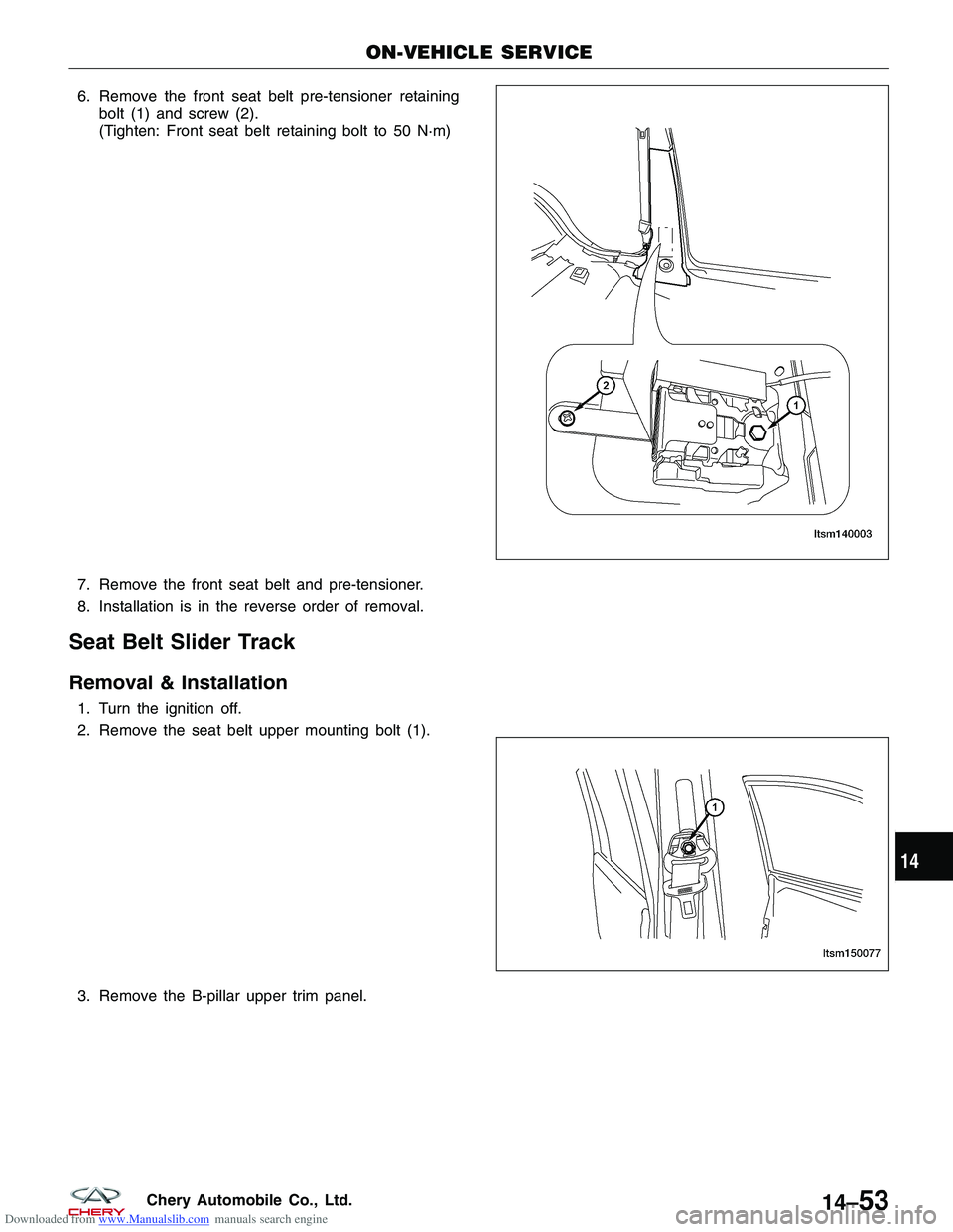
Downloaded from www.Manualslib.com manuals search engine 6. Remove the front seat belt pre-tensioner retainingbolt (1) and screw (2).
(Tighten: Front seat belt retaining bolt to 50 N·m)
7. Remove the front seat belt and pre-tensioner.
8. Installation is in the reverse order of removal.
Seat Belt Slider Track
Removal & Installation
1. Turn the ignition off.
2. Remove the seat belt upper mounting bolt (1).
3. Remove the B-pillar upper trim panel.
ON-VEHICLE SERVICE
LTSM140003
LTSM150077
14
14–53Chery Automobile Co., Ltd.
Page 1583 of 1903
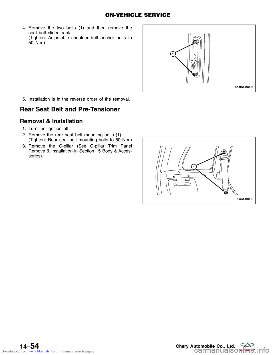
Downloaded from www.Manualslib.com manuals search engine 4. Remove the two bolts (1) and then remove theseat belt slider track.
(Tighten: Adjustable shoulder belt anchor bolts to
50 N·m)
5. Installation is in the reverse order of the removal.
Rear Seat Belt and Pre-Tensioner
Removal & Installation
1. Turn the ignition off.
2. Remove the rear seat belt mounting bolts (1). (Tighten: Rear seat belt mounting bolts to 50 N·m)
3. Remove the C-pillar (See C-pillar Trim Panel Remove & Installation in Section 15 Body & Acces-
sories).
ON-VEHICLE SERVICE
BESM140006
LTSM140005
14–54Chery Automobile Co., Ltd.
Page 1584 of 1903
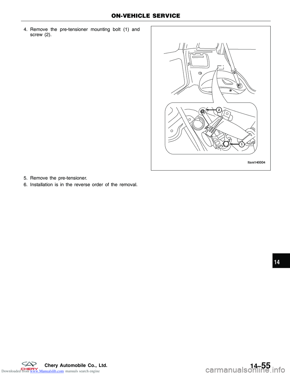
Downloaded from www.Manualslib.com manuals search engine 4. Remove the pre-tensioner mounting bolt (1) andscrew (2).
5. Remove the pre-tensioner.
6. Installation is in the reverse order of the removal.
ON-VEHICLE SERVICE
LTSM140004
14
14–55Chery Automobile Co., Ltd.
Page 1585 of 1903
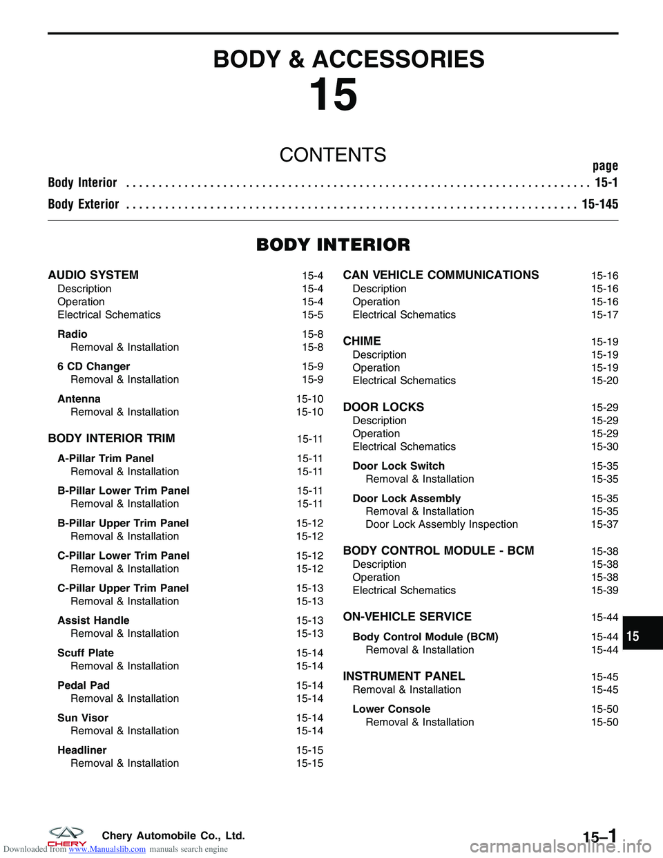
Downloaded from www.Manualslib.com manuals search engine BODY & ACCESSORIES
15
CONTENTSpage
Body Interior ........................................................................\
15-1
Body Exterior ...................................................................... 15-145
BODY INTERIOR
AUDIO SYSTEM15-4
Description 15-4
Operation 15-4
Electrical Schematics 15-5
Radio 15-8
Removal & Installation 15-8
6 CD Changer 15-9
Removal & Installation 15-9
Antenna 15-10
Removal & Installation 15-10
BODY INTERIOR TRIM15-11
A-Pillar Trim Panel 15-11
Removal & Installation 15-11
B-Pillar Lower Trim Panel 15-11
Removal & Installation 15-11
B-Pillar Upper Trim Panel 15-12
Removal & Installation 15-12
C-Pillar Lower Trim Panel 15-12
Removal & Installation 15-12
C-Pillar Upper Trim Panel 15-13
Removal & Installation 15-13
Assist Handle 15-13
Removal & Installation 15-13
Scuff Plate 15-14
Removal & Installation 15-14
Pedal Pad 15-14
Removal & Installation 15-14
Sun Visor 15-14
Removal & Installation 15-14
Headliner 15-15
Removal & Installation 15-15
CAN VEHICLE COMMUNICATIONS15-16
Description 15-16
Operation 15-16
Electrical Schematics 15-17
CHIME15-19
Description 15-19
Operation 15-19
Electrical Schematics 15-20
DOOR LOCKS15-29
Description 15-29
Operation 15-29
Electrical Schematics 15-30
Door Lock Switch 15-35
Removal & Installation 15-35
Door Lock Assembly 15-35
Removal & Installation 15-35
Door Lock Assembly Inspection 15-37
BODY CONTROL MODULE - BCM15-38
Description 15-38
Operation 15-38
Electrical Schematics 15-39
ON-VEHICLE SERVICE15-44
Body Control Module (BCM) 15-44
Removal & Installation 15-44
INSTRUMENT PANEL15-45
Removal & Installation 15-45
Lower Console 15-50
Removal & Installation 15-50
15
15–1Chery Automobile Co., Ltd.
Page 1586 of 1903
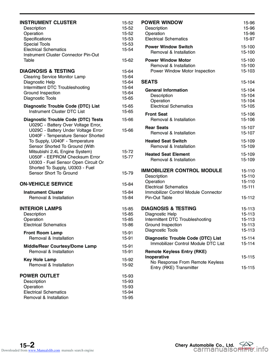
Downloaded from www.Manualslib.com manuals search engine INSTRUMENT CLUSTER15-52
Description 15-52
Operation 15-52
Specifications 15-53
Special Tools 15-53
Electrical Schematics 15-54
Instrument Cluster Connector Pin-Out
Table 15-62
DIAGNOSIS & TESTING15-64
Clearing Service Monitor Lamp 15-64
Diagnostic Help 15-64
Intermittent DTC Troubleshooting 15-64
Ground Inspection 15-64
Diagnostic Tools 15-65
Diagnostic Trouble Code (DTC) List 15-65
Instrument Cluster DTC List 15-65
Diagnostic Trouble Code (DTC) Tests 15-66
U029C - Battery Over Voltage Error,
U029C - Battery Under Voltage Error 15-66
U040F - Temperature Sensor Shorted
To Supply, U040F - Temperature
Sensor Shorted To Ground (With
Mitsubishi 2.4L Engine System) 15-72
U050F - EEPROM Checksum Error 15-77
U0303 - Fuel Sensor Open Circuit Or
Shorted To Supply, U0303 - Fuel
Sensor Short To Ground 15-79
ON-VEHICLE SERVICE15-84
Instrument Cluster 15-84
Removal & Installation 15-84
INTERIOR LAMPS15-85
Description 15-85
Operation 15-85
Electrical Schematics 15-86
Front Room Lamp 15-91
Removal & Installation 15-91
Middle/Rear Courtesy/Dome Lamp 15-91
Removal & Installation 15-91
Key Hole Lamp 15-92
Removal & Installation 15-92
POWER OUTLET15-93
Description 15-93
Operation 15-93
Electrical Schematics 15-94
Removal & Installation 15-95
POWER WINDOW15-96
Description 15-96
Operation 15-96
Electrical Schematics 15-97
Power Window Switch 15-100
Removal & Installation 15-100
Power Window Motor 15-100
Removal & Installation 15-100
Power Window Motor Inspection 15-103
SEATS15-104
General Information 15-104
Description 15-104
Operation 15-104
Electrical Schematics 15-105
Front Seat 15-106
Removal & Installation 15-106
Rear Seats 15-107
Removal & Installation 15-107
Heated Seat Switch 15-109
Removal & Installation 15-109
Heated Seat Element 15-109
Removal & Installation 15-109
IMMOBILIZER CONTROL MODULE15-110
Description 15-110
Operation 15-110
Electrical Schematics 15-111
Immobilizer Control Module Connector
Pin-Out Table 15-112
DIAGNOSIS & TESTING15-113
Diagnostic Help 15-113
Intermittent DTC Troubleshooting 15-113
Ground Inspection 15-113
Diagnostic Tools 15-113
Diagnostic Trouble Code (DTC) List 15-114
Immobilizer Control Module DTC List 15-114
Remote Keyless Entry (RKE)
Inoperative 15-115
No Response From Remote Keyless
Entry (RKE) Transmitter 15-115
15–2Chery Automobile Co., Ltd.
Page 1587 of 1903

Downloaded from www.Manualslib.com manuals search engine Diagnostic Trouble Code (DTC) Tests15-117
B1000 - ECU Defect: Internal Errors 15-117
B3042 - W-Line Short Circuit To
Ground, B3043 - W-Line Short Circuit
To Battery 15-121
B3050 - Relay External Line Short
Circuit To Ground Or Open Circuit,
Relay External Line Malfunction,
B3053 - Relay External Line Short
Circuit To Battery 15-126B3055 - No Transponder Modulation Or
No Transponder, B3056 - No
Transponder Fixed Code Programmed 15-132
B3060 - Unprogrammed Transponder
Fixed Code Received, B3061 -
Disturbed Or No Challenge/Response
Transponder Communication, B3077 -
Read-Only Transponder Detected
15-138
ON-VEHICLE SERVICE15-144
Immobilizer Control Module 15-144
Removal & Installation 15-144
BODY AND ACCESSORIES - BODY INTERIOR
15
15–3Chery Automobile Co., Ltd.
Page 1588 of 1903
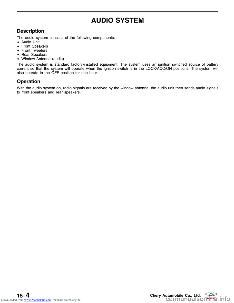
Downloaded from www.Manualslib.com manuals search engine AUDIO SYSTEM
Description
The audio system consists of the following components:
•Audio Unit
• Front Speakers
• Front Tweeters
• Rear Speakers
• Window Antenna (audio)
The audio system is standard factory-installed equipment. The system uses an ignition switched source of battery
current so that the system will operate when the ignition switch is in the LOCK/ACC/ON positions. The system will
also operate in the OFF position for one hour.
Operation
With the audio system on, radio signals are received by the window antenna, the audio unit then sends audio signals
to front speakers and rear speakers.
15–4Chery Automobile Co., Ltd.
Page 1589 of 1903
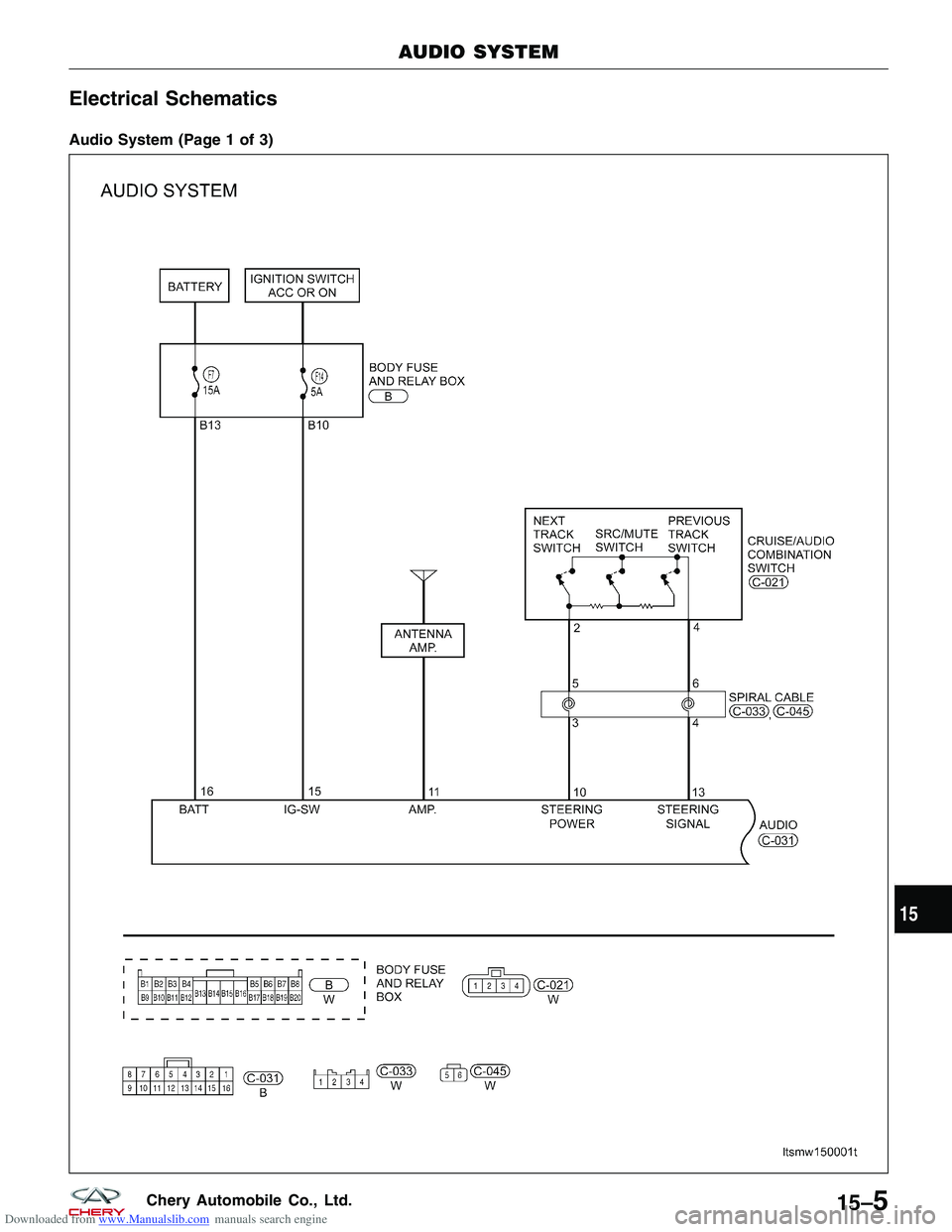
Downloaded from www.Manualslib.com manuals search engine Electrical Schematics
Audio System (Page 1 of 3)
AUDIO SYSTEM
LTSMW150001T
15
15–5Chery Automobile Co., Ltd.
Page 1590 of 1903
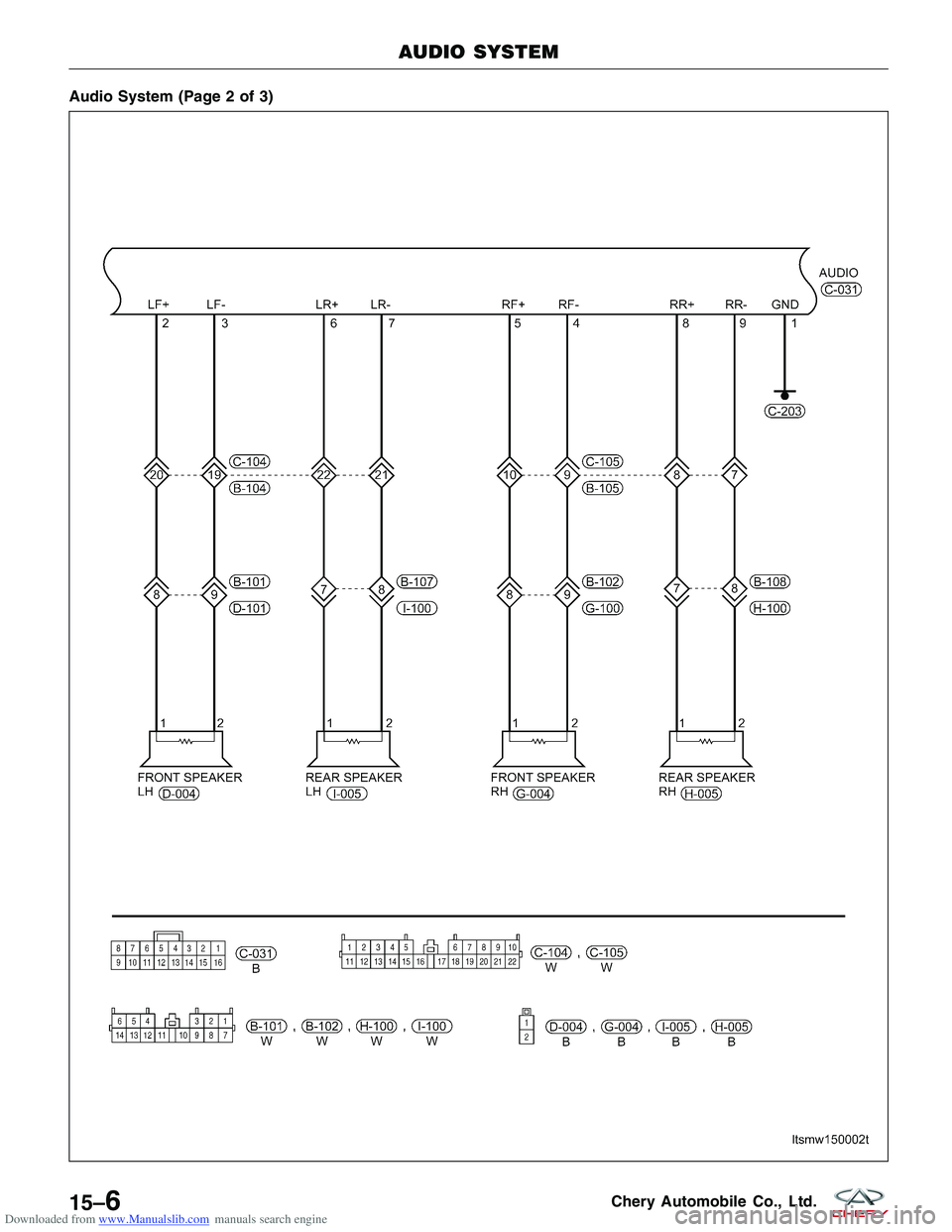
Downloaded from www.Manualslib.com manuals search engine Audio System (Page 2 of 3)
AUDIO SYSTEM
LTSMW150002T
15–6Chery Automobile Co., Ltd.