CHERY TIGGO 2009 Service Repair Manual
Manufacturer: CHERY, Model Year: 2009,
Model line: TIGGO,
Model: CHERY TIGGO 2009
Pages: 1903, PDF Size: 33.38 MB
CHERY TIGGO 2009 Service Repair Manual
TIGGO 2009
CHERY
CHERY
https://www.carmanualsonline.info/img/53/56852/w960_56852-0.png
CHERY TIGGO 2009 Service Repair Manual
Trending: cruise control, wheel torque, coolant temperature, brake light, air suspension, change time, transmission
Page 1591 of 1903
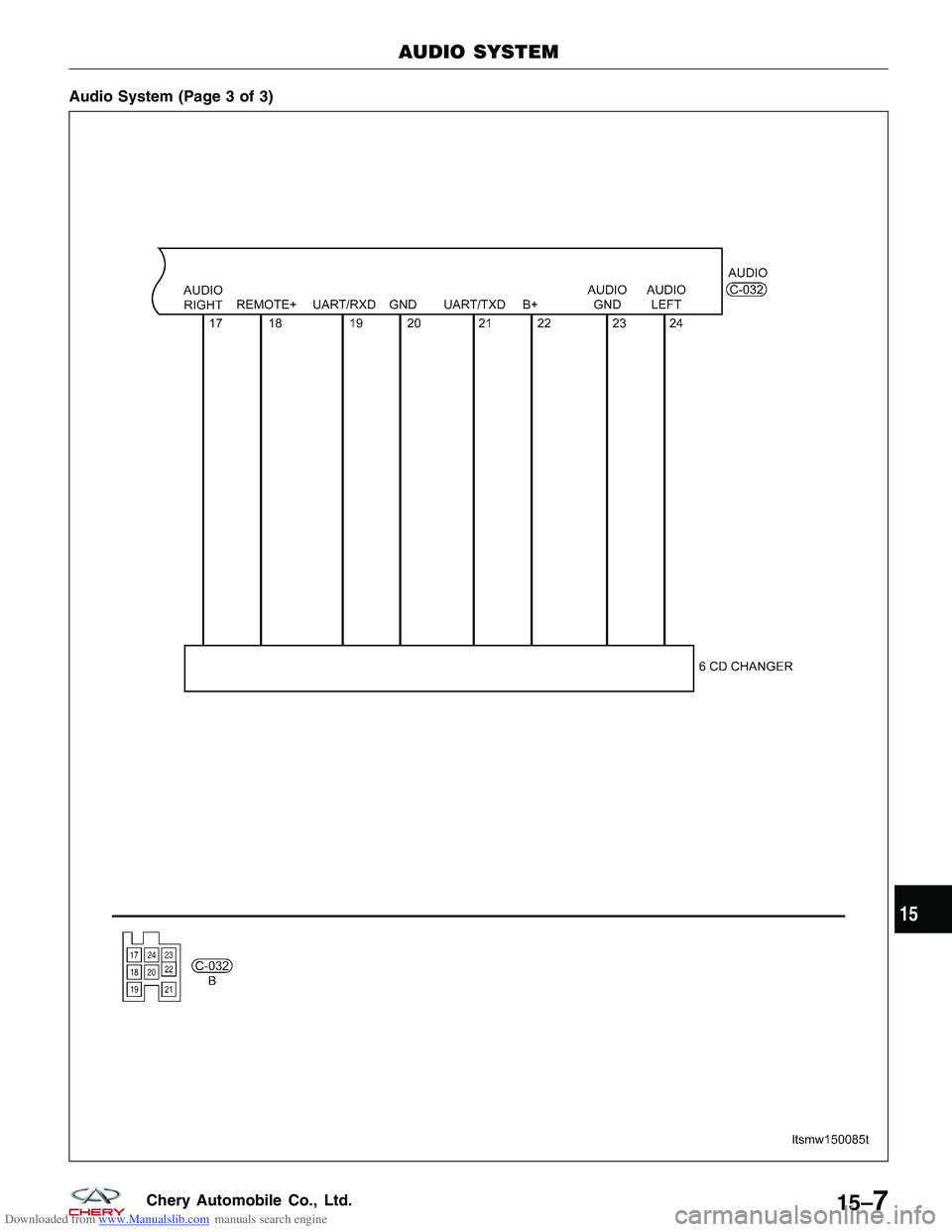
Downloaded from www.Manualslib.com manuals search engine Audio System (Page 3 of 3)
AUDIO SYSTEM
LTSMW150085T
15
15–7Chery Automobile Co., Ltd.
Page 1592 of 1903
Downloaded from www.Manualslib.com manuals search engine Radio
Removal & Installation
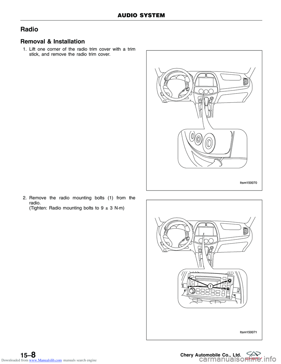
1. Lift one corner of the radio trim cover with a trimstick, and remove the radio trim cover.
2. Remove the radio mounting bolts (1) from the radio.
(Tighten: Radio mounting bolts to9±3N·m)
AUDIO SYSTEM
LTSM150070
LTSM150071
15–8Chery Automobile Co., Ltd.
Page 1593 of 1903
Downloaded from www.Manualslib.com manuals search engine 3. Disconnect the electrical connectors.
4. Remove the radio.
5. Installation is in the reverse order of removal.
6 CD Changer
Removal & Installation
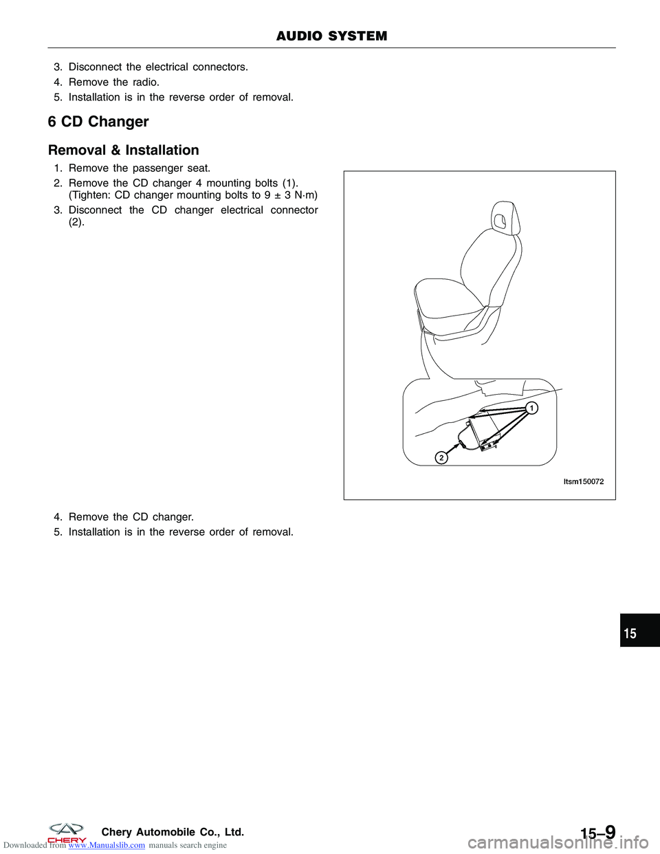
1. Remove the passenger seat.
2. Remove the CD changer 4 mounting bolts (1).(Tighten: CD changer mounting bolts to9±3N·m)
3. Disconnect the CD changer electrical connector (2).
4. Remove the CD changer.
5. Installation is in the reverse order of removal.
AUDIO SYSTEM
LTSM150072
15
15–9Chery Automobile Co., Ltd.
Page 1594 of 1903
Downloaded from www.Manualslib.com manuals search engine Antenna
Removal & Installation
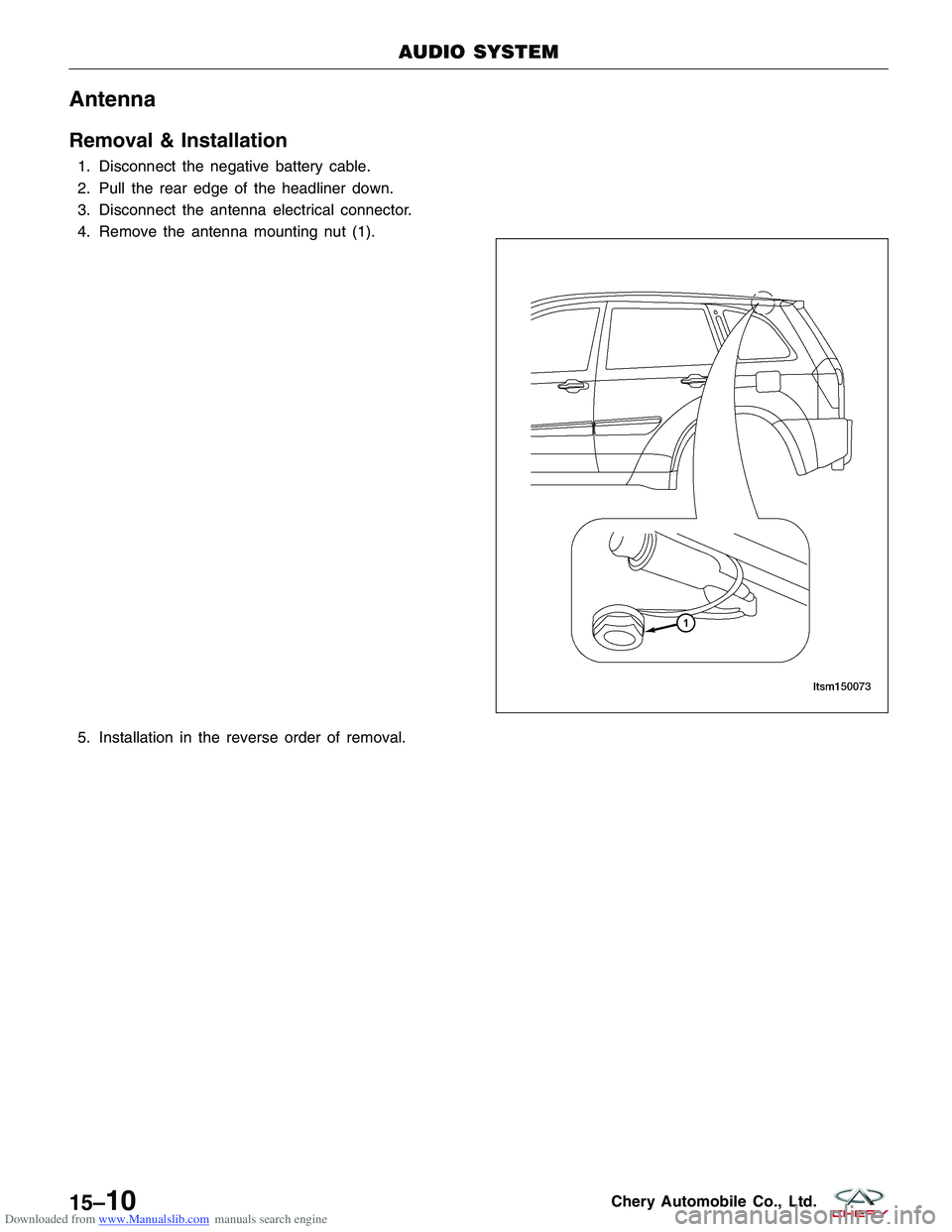
1. Disconnect the negative battery cable.
2. Pull the rear edge of the headliner down.
3. Disconnect the antenna electrical connector.
4. Remove the antenna mounting nut (1).
5. Installation in the reverse order of removal.
AUDIO SYSTEM
LTSM150073
15–10Chery Automobile Co., Ltd.
Page 1595 of 1903
Downloaded from www.Manualslib.com manuals search engine BODY INTERIOR TRIM
A-Pillar Trim Panel
Removal & Installation
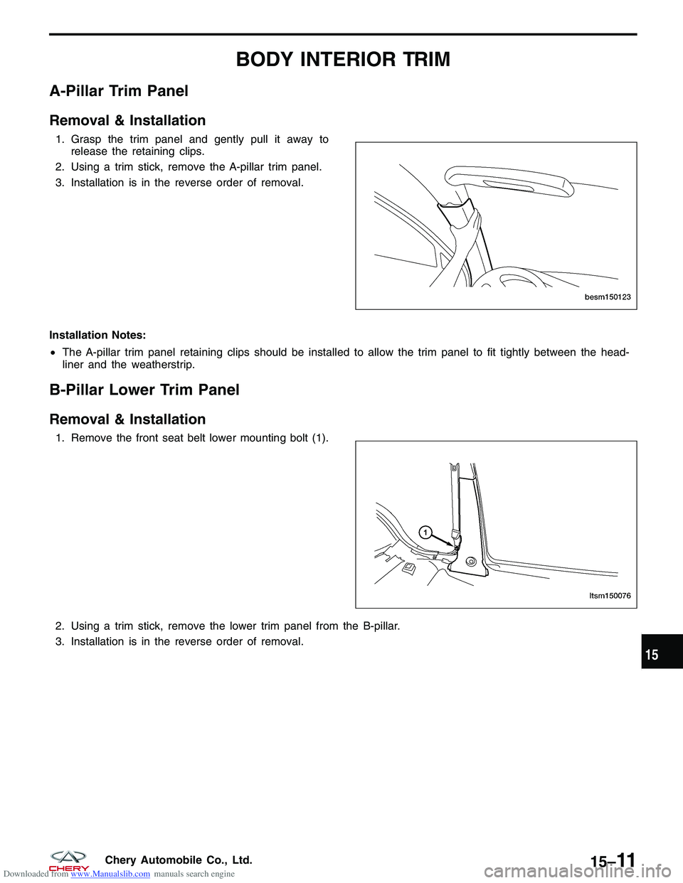
1. Grasp the trim panel and gently pull it away torelease the retaining clips.
2. Using a trim stick, remove the A-pillar trim panel.
3. Installation is in the reverse order of removal.
Installation Notes:
• The A-pillar trim panel retaining clips should be installed to allow the trim panel to fit tightly between the head-
liner and the weatherstrip.
B-Pillar Lower Trim Panel
Removal & Installation
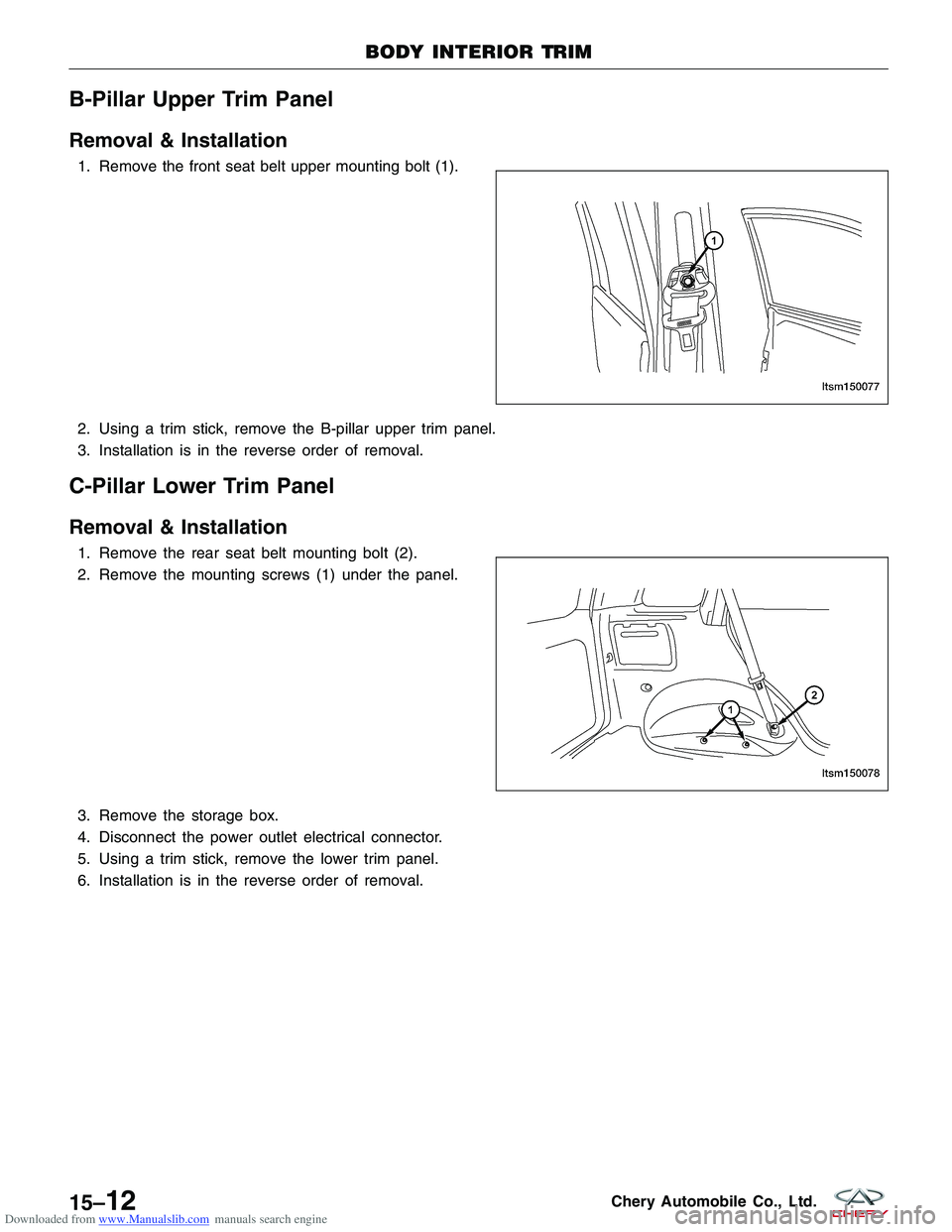
1. Remove the front seat belt lower mounting bolt (1).
2. Using a trim stick, remove the lower trim panel from the B-pillar.
3. Installation is in the reverse order of removal.
BESM150123
LTSM150076
15
15–11Chery Automobile Co., Ltd.
Page 1596 of 1903
Downloaded from www.Manualslib.com manuals search engine B-Pillar Upper Trim Panel
Removal & Installation
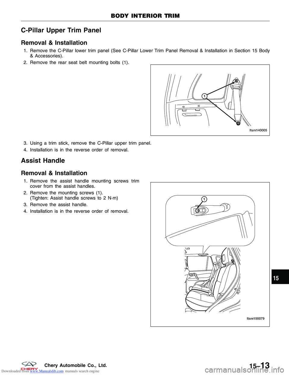
1. Remove the front seat belt upper mounting bolt (1).
2. Using a trim stick, remove the B-pillar upper trim panel.
3. Installation is in the reverse order of removal.
C-Pillar Lower Trim Panel
Removal & Installation
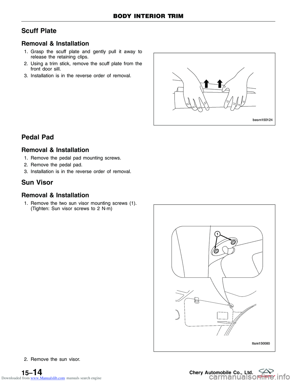
1. Remove the rear seat belt mounting bolt (2).
2. Remove the mounting screws (1) under the panel.
3. Remove the storage box.
4. Disconnect the power outlet electrical connector.
5. Using a trim stick, remove the lower trim panel.
6. Installation is in the reverse order of removal.
BODY INTERIOR TRIM
LTSM150077
LTSM150078
15–12Chery Automobile Co., Ltd.
Page 1597 of 1903
Downloaded from www.Manualslib.com manuals search engine C-Pillar Upper Trim Panel
Removal & Installation
1. Remove the C-Pillar lower trim panel (See C-Pillar Lower Trim Panel Removal & Installation in Section 15 Body& Accessories).
2. Remove the rear seat belt mounting bolts (1).
3. Using a trim stick, remove the C-Pillar upper trim panel.
4. Installation is in the reverse order of removal.
Assist Handle
Removal & Installation
1. Remove the assist handle mounting screws trim cover from the assist handles.
2. Remove the mounting screws (1). (Tighten: Assist handle screws to 2 N·m)
3. Remove the assist handle.
4. Installation is in the reverse order of removal.
BODY INTERIOR TRIM
LTSM140005
LTSM150079
15
15–13Chery Automobile Co., Ltd.
Page 1598 of 1903
Downloaded from www.Manualslib.com manuals search engine Scuff Plate
Removal & Installation
1. Grasp the scuff plate and gently pull it away torelease the retaining clips.
2. Using a trim stick, remove the scuff plate from the front door sill.
3. Installation is in the reverse order of removal.
Pedal Pad
Removal & Installation
1. Remove the pedal pad mounting screws.
2. Remove the pedal pad.
3. Installation is in the reverse order of removal.
Sun Visor
Removal & Installation
1. Remove the two sun visor mounting screws (1). (Tighten: Sun visor screws to 2 N·m)
2. Remove the sun visor.
BODY INTERIOR TRIM
BESM150124
LTSM150080
15–14Chery Automobile Co., Ltd.
Page 1599 of 1903
Downloaded from www.Manualslib.com manuals search engine 3. Installation is in the reverse order of removal.
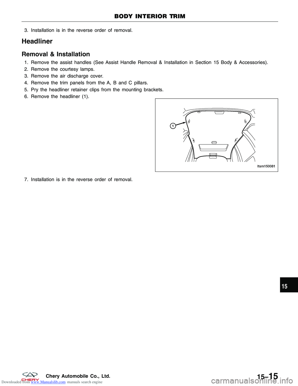
Headliner
Removal & Installation
1. Remove the assist handles (See Assist Handle Removal & Installation in Section 15 Body & Accessories).
2. Remove the courtesy lamps.
3. Remove the air discharge cover.
4. Remove the trim panels from the A, B and C pillars.
5. Pry the headliner retainer clips from the mounting brackets.
6. Remove the headliner (1).
7. Installation is in the reverse order of removal.
BODY INTERIOR TRIM
LTSM150081
15
15–15Chery Automobile Co., Ltd.
Page 1600 of 1903
Downloaded from www.Manualslib.com manuals search engine CAN VEHICLE COMMUNICATIONS
Description
Controller Area Network (CAN) communication is a multiplex communication system. The CAN system allows the
vehicles electronic modules to transmit and receive data. The following electronic modules are located on the CAN
network:
•Transaxle Control Module (TCM)
• Engine Control Module (ECM)
• CAN Converter
Operation
The CAN network uses a twisted pair of circuits to transmit data (+) and data (-). The data (+) and the data (-)
circuits are each regulated to approximately 2.5 volts during neutral or rested network traffic. As bus messages are
sent on the data (+) circuit, voltage is increased by approximately 1.0 volt. Inversely, the data (-) circuit is reduced by
approximately 1.0 volt when a bus message is sent. Multiple bus messages can be sent over the CAN circuits allow-
ing multiple modules to communicate with each other.
15–16Chery Automobile Co., Ltd.
Trending: service indicator, spark plugs replace, engine overheat, Cluster, glove box, weight, coolant capacity
