relay CHEVROLET CAMARO 1967 1.G Chassis Owner's Manual
[x] Cancel search | Manufacturer: CHEVROLET, Model Year: 1967, Model line: CAMARO, Model: CHEVROLET CAMARO 1967 1.GPages: 659, PDF Size: 114.24 MB
Page 333 of 659
ENGINE-ELECTRICAL 6Y-8
1
FIELD RELAY^I^p2
"LATCH"
^PFN?^
"P1
TERMINAL
JyJvJCTl^
NO. 2 TERMINAD^5^^^«
NO.
3 TERMINAL ^S5«£
NO.
4 TERMINAL ^^^
m
# / VOLTAGE
¥ REGULATOR
1
ACCESS PLUG TO
VOLTAGE ADJUSTMENT
No 4 TERMINAL
Double Contact
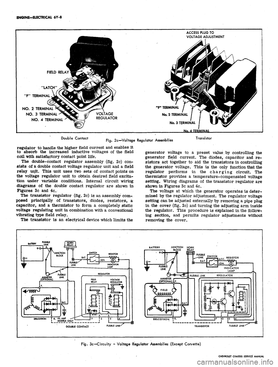
Fig.
2c—Voltage Regulator Assemblies
Transistor
regulator to handle the higher field current and enables it
to absorb the increased inductive voltages of the field
coil with satisfactory contact point life.
The double-contact regulator assembly (fig. 2c) con-
sists of a double contact voltage regulator unit and a field
relay unit. This unit uses two sets of contact points on
the voltage regulator unit to obtain desired field excita-
tion under variable conditions. Internal circuit wiring
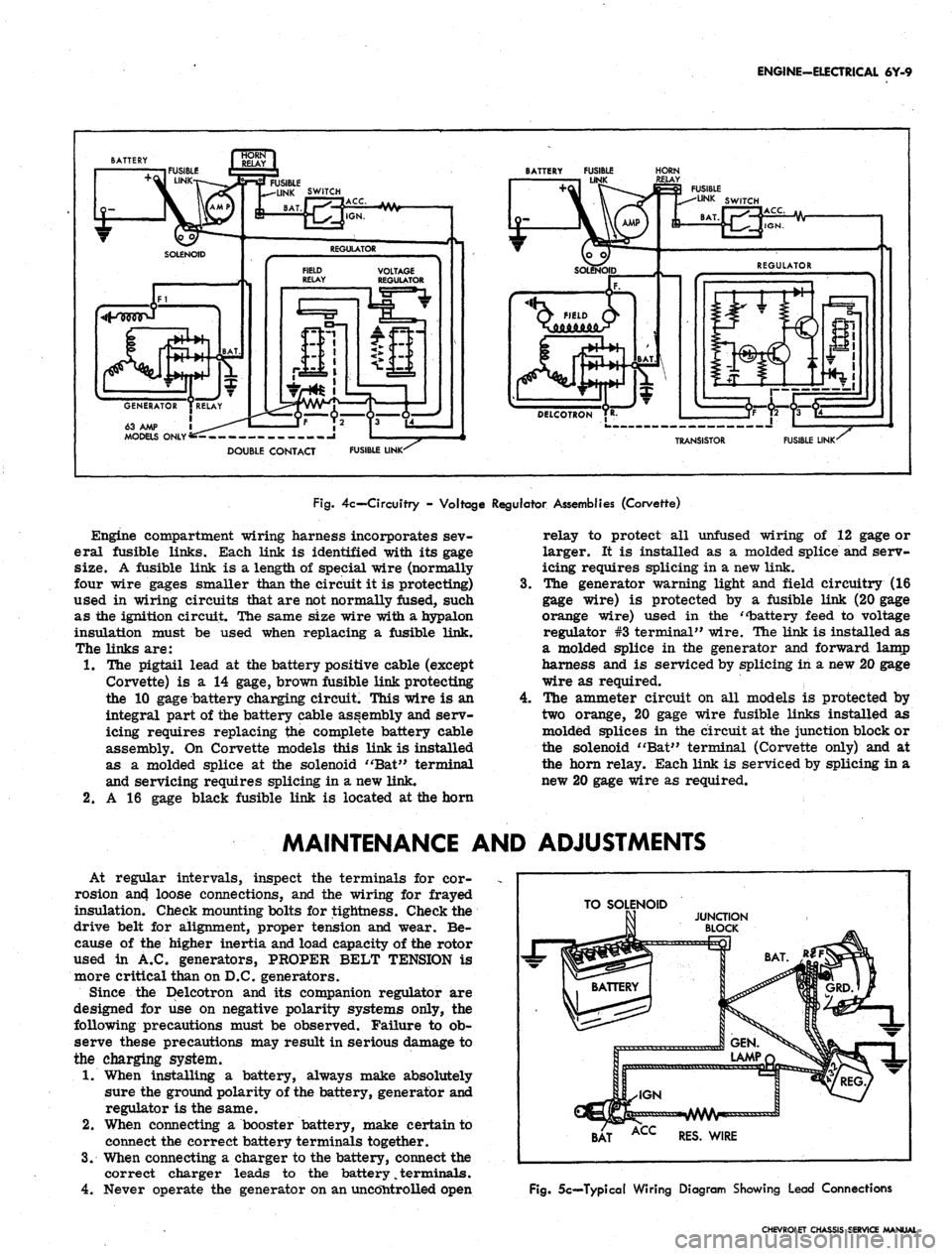
diagrams of the double contact regulator are shown in
Figures 3c and 4c.
The transistor regulator (fig. 2c) is an assembly com-
posed principally of transistors, diodes, resistors, a
capacitor, and a thermistor to form a completely static
voltage regulating unit in combination with a conventional
vibrating type field relay.
The transistor is an electrical device which limits the
generator voltage to a preset value by controlling the
generator field current. The diodes, capacitor and re-
sistors act together to aid the transistors in controlling
the generator voltage. This is the only function that the
regulator performs in the charging circuit. The
thermistor provides a temperature-compensated voltage
setting. Wiring diagrams of the transistor regulator are
shown in Figures 3c and 4c.
The voltage at which the generator operates is deter-
mined by the regulator adjustment. The regulator voltage
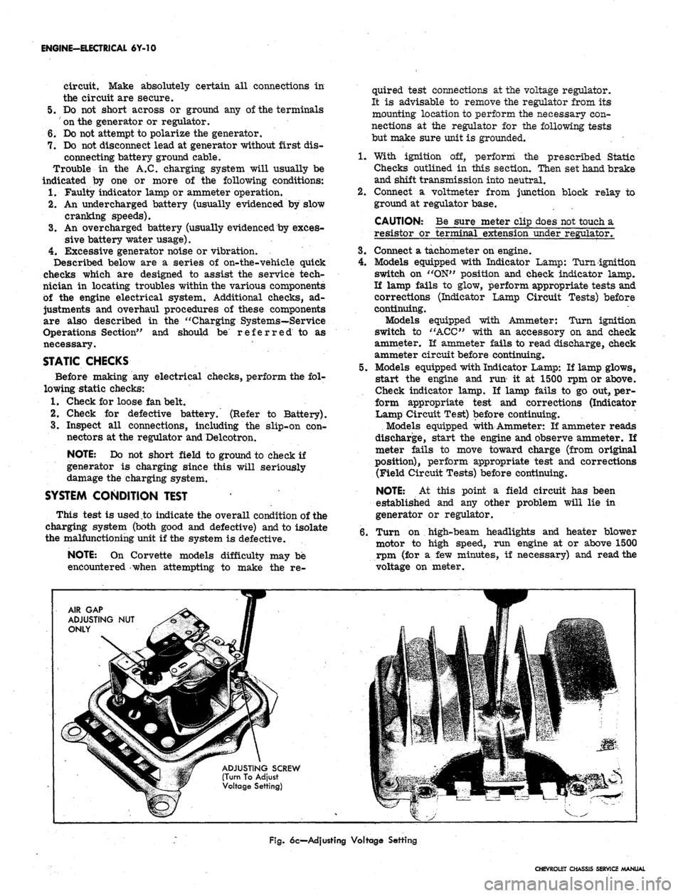
setting can be adjusted externally by removing a pipe plug
in the cover (fig. 2c) and turning the adjusting arm inside
the regulator. This procedure is explained in the followr
ing section, and permits regulator adjustments without
removing the cover.
FUSIBLE
DOUBLE CONTACT
FUSIBLE LINK-^
JUNCTION HORN
BLOCK RELAY
RESISTOR
Q FIELD Q>
DELCOTRON TR-
TRANSISTOR
FUSIBLE LINK-
Fig.
3c-Circuity - Voltage Regulator Assemblies (Except Corvette)
CHEVROLET CHASSIS SERVICE MANUAL
Page 334 of 659
ENGINE-ELECTRICAL 6Y-9
63 AMP 1
MODELS ONLY'
BATTERY FUSIBLE
LINK
HORN
FUSIBLE LINK'
TRANSISTOR
FUSIBLE LINK'
Fig.
4c— Circuitry - Voltage Regulator Assemblies (Corvette)
Engine compartment wiring harness incorporates sev-
eral fusible links. Each link is identified with its gage
size. A fusible link is a length of special wire (normally
four wire gages smaller than the circuit it is protecting)
used in wiring circuits that are not normally fused, such
as the ignition circuit. The same size wire with a hypalon
insulation must be used when replacing a fusible link.
The links are:
1.
The pigtail lead at the battery positive cable (except
Corvette) is a 14 gage, brown fusible link protecting
the 10 gage battery charging circuit. This wire is an
integral part of the battery cable assembly and serv-
icing requires replacing the complete battery cable
assembly. On Corvette models this link is installed
as a molded splice at the solenoid "Bat" terminal
and servicing requires splicing in a new link.
2.
A 16 gage black fusible link is located at the horn
4.
relay to protect all unfused wiring of 12 gage or
larger. It is installed as a molded splice and serv-
icing requires splicing in a new link.
The generator warning light and field circuitry (16
gage wire) is protected by a fusible link (20 gage
orange wire) used in the "battery feed to voltage
regulator #3 terminal" wire. The link is installed as
a molded splice in the generator and forward lamp
harness and is serviced by splicing in a new 20 gage
wire as required.
The ammeter circuit on all models is protected by
two orange, 20 gage wire fusible links installed as
molded splices in the circuit at the junction block or
the solenoid "Bat" terminal (Corvette only) and at
the horn relay. Each link is serviced by splicing in a
new 20 gage wire as required.
MAINTENANCE AND ADJUSTMENTS
At regular intervals, inspect the terminals for cor-
rosion an4 loose connections, and the wiring for frayed
insulation. Check mounting bolts for tightness. Check the
drive belt for alignment, proper tension and wear. Be-
cause of the higher inertia and load capacity of the rotor
used in A.C. generators, PROPER BELT TENSION is
more critical than on D.C. generators.
Since the Delcotron and its companion regulator are
designed for use on negative polarity systems only, the
following precautions must be observed. Failure to ob-
serve these precautions may result in serious damage to
the charging system.
1.
When installing a battery, always make absolutely
sure the ground polarity of the battery, generator and
regulator is the same.
2.
When connecting a booster battery, make certain to
connect the correct battery terminals together.
3.
When connecting a charger to the battery, connect the
correct charger leads to the battery
%
terminals.
4.
Never operate the generator on an uncontrolled open
TO SOLENOID
BAT ACC RES. WIRE
Fig.
5c—Typical Wiring Diagram Showing Lead Connections
CHEVROLET CHASSIS SERVICE MANUAL
Page 335 of 659
ENGINE-ELECTRICAL 6Y-10
circuit. Make absolutely certain all connections in
the circuit are secure.
5.
Do not short across or ground any of the terminals
on the generator or regulator.
6. Do not attempt to polarize the generator.
7.
Do not disconnect lead at generator without first dis-
connecting battery ground cable.
Trouble in the A.C. charging system will usually be
indicated by one or more of the following conditions:
1.
Faulty indicator lamp or ammeter operation.
2.
An undercharged battery (usually evidenced by slow
cranking speeds).
3.
An overcharged battery (usually evidenced by exces-
sive battery water usage).
4.
Excessive generator noise or vibration.
Described below are a series of on-the-vehicle quick
checks which are designed to assist the service tech-
nician in locating troubles within the various components
of the engine electrical system. Additional checks, ad-
justments and overhaul procedures of these components
are also described in the "Charging Systems—Service
Operations Section" and should be referred to as
necessary.
STATIC CHECKS
Before making any electrical checks, perform the fol-
lowing static checks:
1.
Check for loose fan belt.
2.
Check for defective battery. (Refer to Battery).
3.
Inspect all connections, including the slip-on con-
nectors at the regulator and Delcotron.
NOTE: Do not short field to ground to check if
generator is charging since this will seriously
damage the charging system.
SYSTEM CONDITION TEST
This test is used .to indicate the overall condition of the
charging system (both good and defective) and to isolate
the malfunctioning unit if the system is defective.
NOTE: On Corvette models difficulty may be
encountered -when attempting to make the re-
quired test connections at the voltage regulator.
It is advisable to remove the regulator from its
mounting location to perform the necessary con-
nections at the regulator for the following tests
but make sure unit is grounded.
1.
With ignition off, perform the prescribed Static
Checks outlined in this section. Then set hand brake
and shift transmission
into
neutral.
2.
Connect a voltmeter from junction block relay to
ground at regulator base.
CAUTION: Be sure meter clip does not touch a
resistor or terminal extension under regulator,
3.
Connect a tachometer on engine.
4.
Models equipped with Indicator Lamp: Turn ignition
switch on "ON" position and check indicator lamp.
If lamp fails to glow, perform appropriate tests and
corrections (Indicator Lamp Circuit Tests) before
continuing.
Models equipped with Ammeter: Turn ignition
switch to "ACC" with an accessory on and check
ammeter. If ammeter fails to read discharge, check
ammeter circuit before continuing.
5.
Models equipped with Indicator Lamp: If lamp glows,
start the engine and run' it at 1500 rpm or above.
Check indicator lamp. If lamp fails to go out, per-
form appropriate test and corrections (Indicator
Lamp Circuit Test) before continuing.
Models equipped with Ammeter: If ammeter reads
discharge, start the engine and observe ammeter. If
meter fails to move toward charge (from original
position), perform appropriate test and corrections
(Field Circuit Tests) before continuing.
NOTE: At this point a field circuit has been
established and any other problem will lie in
generator or regulator.
6. Turn on high-beam headlights and heater blower
motor to high speed, run engine at or above 1500
rpm (for a few minutes, if necessary) and read the
voltage on meter.
AIR GAP
ADJUSTING NUT
ONLY
ADJUSTING SCREW
(Turn To Adjust
Voltage Setting)
Fig.
6c—Adjusting Voltage Setting
CHEVROLET CHASSIS SERVICE MANUAL
Page 336 of 659
ENGINE-ELECTRICAL 6Y-11
I
BAT
JUNCTION BLOCK
DELCOTRON
—GRQ
BATTERY
&HJVVWV
0 VA OHM TEST RELAY >
RESISTOR [ 1 d
FUSIBLE
LINK
TO CRANKING
MOTOR
Ik
REGULATOR
VOLTMETER
FUSIBLE LINK
IGN.
SWITCH
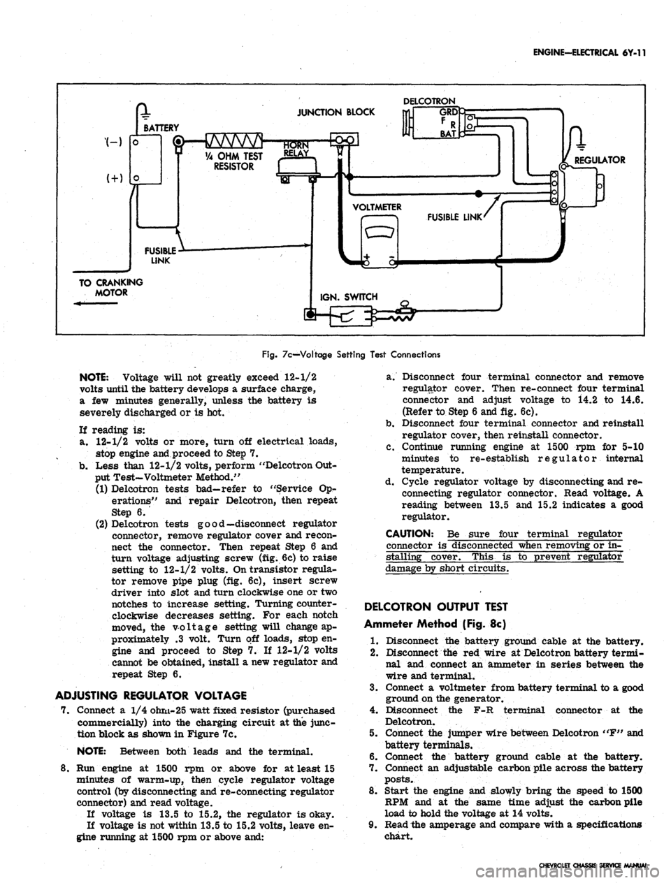
Fig.
7c—Voltage Setting Test Connections
NOTE:
Voltage will not greatly exceed 12-1/2
volts until the battery develops a surface charge,
a few minutes generally, unless the battery is
severely discharged or is hot.
If reading is:
a. 12-1/2 volts or more, turn off electrical loads,
stop engine and proceed to Step 7.
b.
Less than 12-1/2 volts, perform "Delcotron Out-
put Test-Voltmeter Method."
(1) Delcotron tests bad—refer to "Service Op-
erations" and repair Delcotron, then repeat
Step 6.
(2) Delcotron tests good—disconnect regulator
connector, remove regulator cover and recon-
nect the connector. Then repeat Step 6 and
turn voltage adjusting screw (fig. 6c) to raise
setting to 12-1/2 volts. On transistor regula-
tor remove pipe plug (fig. 6c), insert screw
driver into slot and turn clockwise one or two
notches to increase setting. Turning counter-
clockwise decreases setting. For each notch
moved, the voltage setting will change ap-
proximately .3 volt. Turn off loads, stop en-
gine and proceed to Step 7. If 12-1/2 volts
cannot be obtained, install a new regulator and
repeat Step 6.
ADJUSTING REGULATOR VOLTAGE
7. Connect a 1/4 ohm-25 watt fixed resistor (purchased
commercially) into the charging circuit at the junc-
tion block as shown in Figure 7c.
NOTE:
Between both leads and the terminal.
8. Run engine at 1500 rpm or above for at least 15
minutes of warm-up, then cycle regulator voltage
control (by disconnecting and re-connecting regulator
connector) and read voltage.
If voltage is 13.5 to 15.2, the regulator is okay.
If voltage is not within 13.5 to 15.2 volts, leave en-
gine running at 1500 rpm or above and:
a. Disconnect four terminal connector and remove
regulator cover. Then re-connect four terminal
connector and adjust voltage to i4.2 to 14.6.
(Refer to Step 6 and fig. 6c).
b.
Disconnect four terminal connector and reinstall
regulator cover, then reinstall connector.
c. Continue running engine at 1500 rpm for 5-10
minutes to re-establish regulator internal
temperature.
d. Cycle regulator voltage by disconnecting and re-
connecting regulator connector. Read voltage. A
reading between 13.5 and 15.2 indicates a good
regulator.
CAUTION: Be sure four terminal regulator
connector is disconnected when removing or in-
stalling cover. This is to prevent regulator
damage by short circuits.
DELCOTRON OUTPUT TEST
Ammeter Method (Fig. 8c)
1.
Disconnect the battery ground cable at the battery.
2.
Disconnect the red wire at Delcotron battery termi-
nal and connect an ammeter in series between the
wire and terminal.
3.
Connect a voltmeter from battery terminal to a good
ground on the generator.
4.
Disconnect the F-R terminal connector at the
Delcotron.
5. Connect the jumper wire between Delcotron "F" and
battery terminals.
6. Connect the battery ground cable at the battery.
7. Connect an adjustable carbon pile across the battery
posts.
8. Start the engine and slowly bring the speed to 1500
RPM and at the same time adjust the carbon pile
load to hold the voltage at 14 volts.
9. Read the amperage and compare with a specifications
chart.
CHEVROLET CHASSIS SERVICE MANUAL
Page 337 of 659

ENGINE-ELECTRICAL 6Y-J2
Fig.
8c—Ammeter Method Test Connections
10.
Turn off ignition, disconnect battery ground cable,
and remove all test equipment.
11.
li the Delcotron meets the test specifications, the
problem is not in the generator.
12.
Ti the Delcotron fails to meet the test specifications,
remove it and perform bench tests and make repair
needed.
DELCOTRON DIODE AND FIELD TEST (Fig. 9c)
NOTE:
These tests will indicate good,, shorted
or open field or shorted diode but will not indi-
cate a failed open diode. If output was low and
following tests show good, refer to service op-
erations to determine cause and repair.
1.
Disconnect battery ground cable at battery.
2.
Positive diodes (Test A) connect an ohmmeter be-
tween "R" terminal and "BAT" terminal and note
Fig.
9c-Deicotron Diode and Field Test
reading, then reverse the leads at same terminals
and note this reading. Meter should read high re-
sistance in one direction and low in the other.
3.
Negative diodes (Test B) connect ohmmeter between
"R" terminal and "GRD" and note reading, then
reverse the leads and note this reading. Meter
should read high in one direction and low in the
other.
NOTE:
A high or low reading in both directions
indicates a defective diode.
4.
Open Field Check:
a. Connect an ohmmeter from "F" terminal to
"GRD"
terminal stud and note reading on the
lowest range scale. Meter should read 7 to
20 ohms.
b.
If meter reads zero or excessively high resist-
ance, the Delcotron is faulty.
5. If above tests indicate a defective Delcotron, remove
and completely check Delcotron as outlined under
''Service Operations".
INDICATOR LAMP/INITIAL FIELD
EXCITATION CIRCUIT TESTS (Fig. 10c)
On standard models the indicator lamp circuit provides
initial field excitation (causing lamp to glow). The light
is cancelled by closing the field relay which applies bat-
tery voltage to both sides of bulb (bulb goes out).
The indicator light should glow when ignition switch is
"ON"
and go out almost immediately when engine starts.
Ammeter equipped vehicles use the same initial field
excitation and control circuits as the indicator lamp ex-
cept the lamp is omitted. The continuity tests on both
type vehicles can be made as follows:
If Lamp Fails to Glow or Ammeter Fails to
Function the Possible Causes are:
1.
Faulty bulb or bulb socket.
2.
Faulty ammeter.
3.
An open circuit in wiring, regulator, or field.
4.
A shorted positive diode—(may also cause glow with
ignition switch "OFF").
TEST AS FOLLOWS:
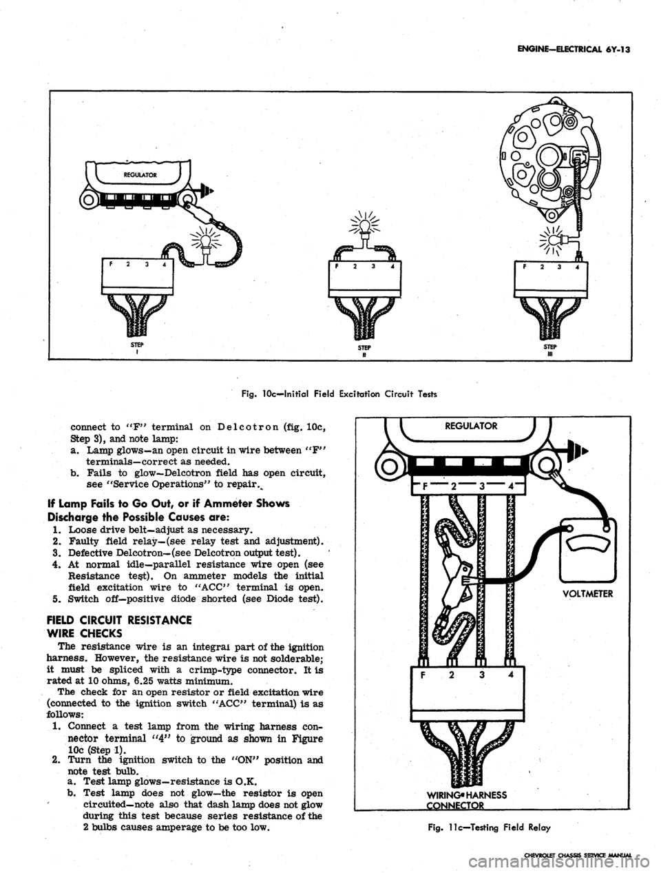
1.
Disconnect connector from regulator and turn
ignition switch to "ON". Connect a test lamp from
connector terminal "4" to ground (fig. 10c, Step 1)
and note test lamp.
a. Lamp fails to glow—check for faulty bulb, socket
or open circuit between switch and regulator con-
nector. Repair as needed.
b.
Light goes on—failure is in regulator, Delcotron,
or wire between "F" terminals on regulator and
Delcotron. Go to Step 2.
2.
Disconnect lamp lead at ground end and connect be-
tween connector "F" and "4" terminals (fig. 10c,
Step 2), and note lamp:
a. Test Lamp glows—problem is in regulator. An
open circuit in regulator or relay is stuck dosed.
See "Service Operations" for repair.
b.
Fails to glow—problem is in wire between "F"
terminals on generator and regulator or infield
windings. Go to Step 3.
3.
Disconnect test lamp at connector "F" terminal and
CHEVROLET CHASSIS SERVICE MANUAL
Page 338 of 659
ENGINE-ELECTRICAL 6Y-13
F 2 3 4
f 2 3 4
F 2 3 4
Fig.
10c—Initial Field Excitation Circuit Tests
connect to "F" terminal on Delcotron (fig. 10c,
Step 3), and note lamp:
a. Lamp glows-an open circuit in wire between "F"
terminals—correct as needed.
b.
Fails to glow—Delcotron field has open circuit,
see "Service Operations" to repair %
If Lamp Fails to Go Out, or if Ammeter Shows
Discharge the Possible Causes are:
1.
Loose drive belt—adjust as necessary.
2.
Faulty field relay—(see relay test and adjustment).
3.
Defective Delcotron—(see Delcotron output test).
4.
At normal idle—parallel resistance wire open (see
Resistance test). On ammeter models the initial
field excitation wire to "ACC" terminal is open.
5. Switch off—positive diode shorted (see Diode test).
FIELD CIRCUIT RESISTANCE
WIRE CHECKS
The resistance wire is an integral part of the ignition
harness. However, the resistance wire is not solderable;
it must be spliced with a crimp-type connector. It is
rated at 10 ohms, 6.25 watts minimum.
The check for an open resistor or field excitation wire
(connected to the ignition switch "ACC" terminal) is as
follows:
1.
Connect a test lamp from the wiring harness con-
nector terminal "4" to ground as shown in Figure
10c (Step 1).
2.
Turn the ignition switch to the "ON" position and
note test bulb.
a. Test lamp glows—resistance is O.K.
b.
Test lamp does not glow—the resistor is open
circuited—note also that dash lamp does not glow
during this test because series resistance of the
2 bulbs causes amperage to be too low.
VOLTMETER
3 4
WIRING*
HARNESS
CONNECTOR
Fig.
11c—Testing Field Relay
CHEVROLET CHASSIS SERVICE MANUAL
Page 339 of 659
ENGINE-ELECTRICAL 6Y-14
VOLTMETER
WIRING HARNESS
CONNECTOR
Fig.
12c—Field Relay Closing Voltage Test
FIELD RELAY CHECKS AND ADJUSTMENT
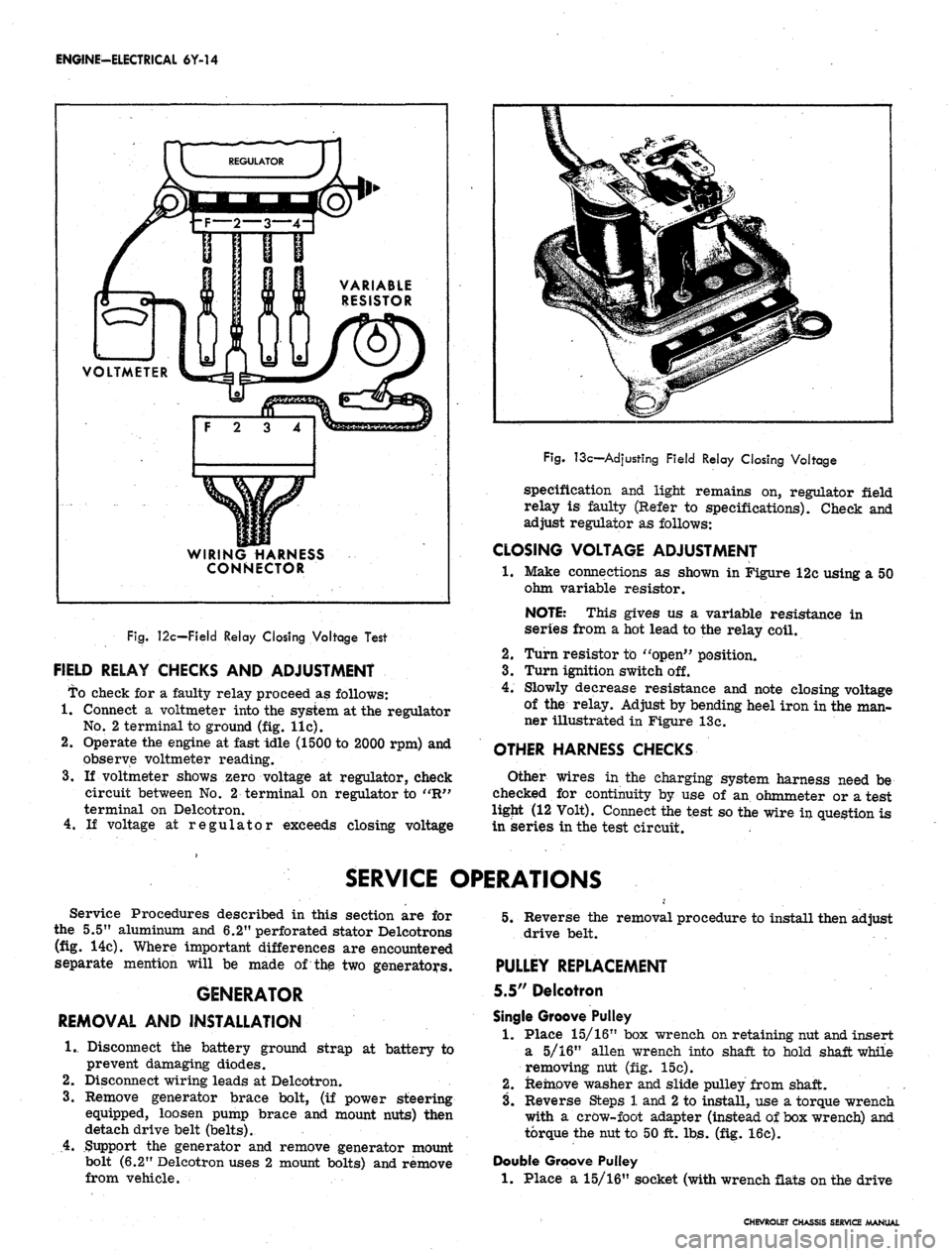
To check for a faulty relay proceed as follows:
1.
Connect a voltmeter into the system at the regulator
No.
2 terminal to ground (fig. lie).
2.
Operate the engine at fast idle (1500 to 2000 rpm) and
observe voltmeter reading.
3.
If voltmeter shows zero voltage at regulator, check
circuit between No. 2 terminal on regulator to "R"
terminal on Delcotron.
4.
If voltage at regulator exceeds closing voltage
Fig.
13c—Adjusting Field Relay Closing Voltage
specification and light remains on, regulator field
relay is faulty (Refer to specifications). Check and
adjust regulator as follows:
CLOSING VOLTAGE ADJUSTMENT
•1.
Make connections as shown in Figure 12c using a 50
ohm variable resistor.
NOTE: This gives us a variable resistance in
series from a hot lead to the relay coil.
2.
Turn resistor to "open" position.
3.
Turn ignition switch off.
4.
Slowly decrease resistance and note closing voltage
of the relay. Adjust by bending heel iron in the man-
ner illustrated in Figure 13c.
OTHER HARNESS CHECKS
Other wires in the charging system harness need be
checked for continuity by use of an ohmmeter or a test
ligjit (12 Volt). Connect the test so the wire in question is
in series in the test circuit.
SERVICE OPERATIONS
Service Procedures described in this section are for
the 5.5" aluminum and 6.2" perforated stator Delcotrons
(fig. 14c). Where important differences are encountered
separate mention will be made of the two generators.
GENERATOR
REMOVAL AND INSTALLATION
1.
Disconnect the battery ground strap at battery to
prevent damaging diodes.
2.
Disconnect wiring leads at Delcotron.
3.
Remove generator brace bolt, (if power steering
equipped, loosen pump brace and mount nuts) then
detach drive belt (belts).
4.
Support the generator and remove generator mount
bolt (6.2" Delcotron uses 2 mount bolts) and remove
from vehicle.
5.
Reverse the removal procedure to install then adjust
drive belt.
PULLEY REPLACEMENT
5.5" Delcotron
Single Groove Pulley
1.
Place 15/16" box wrench on retaining nut and insert
a 5/16" alien wrench into shaft to hold shaft while
removing nut (fig. 15c).
2.
Remove washer and slide pulley from shaft.
3.
Reverse Steps 1 and
2
to install, use a torque wrench
with a crow-foot adapter (instead of box wrench) and
torque the nut to 50 ft. lbs. (fig. 16c).
Double Groove Pulley
1.
Place a 15/16" socket (with wrench flats on the drive
CHEVROLET CHASSIS SERVICE MANUAL
Page 340 of 659

ENGINE-ELECTRICAL 6Y-15
L
RELAY
TERMINAL "F" TERMINAL
"BAT" \ ' /
TERMINAL
/ / /
GRD7
TERMINAL
5.5" SERIES ID DELCOTRON
"BAH"
TERMINAL
^Vs^^^^lijBii^^8C^3^SH|j^^^^^^sH^^Bf- y/
RELAY ^^^"^^^jWwIi^^^^ RELAY
6.2" SERIES 2D, TYPE 150 DELCOTRON
Fig.
14c—Delcotrons - Full View
end or use Adapter J-21501 and a box wrench) on re-
taining nut, insert a 5/16" alien wrench through
socket and adapter into hex on shaft to hold the shaft
while removing the nut.
2.
Remove washer and slide pulley from shaft.
3.
To install, slide pulley and washer on shaft and start
the nut.
4.
Use the socket and adapter with a torque wrench and
tighten-nut to 50 ft. lbs. torque.
BRUSH
REPLACEMENT
6.2"
Delcotron
1.
Remove two nuts retaining the blade connectors and
remove the connectors (fig. 17c). Slide the indicator
light relay wire from the terminal post.
2.
Remove two screws retaining the capacitor and brush
holder to rear end frame, Remove brush holder.
3.
To install brushes, push brushes into holder and
install pin to keep the brushes in holder.
4.
Attach brush assembly and condenser to the end
frame with hex-head stud on the .left side only.
Fig.
15c—Pulley Removal
Fig.
16c—Torqulng Pulley Nut
CHEVROLET CHASSIS SERVICE MANUAL
Page 341 of 659
ENGINE-ELECTRICAL
6Y-16
POINT
OPENINGJL
Fig. 17c-6.2"
Brush
Holder
Assembly
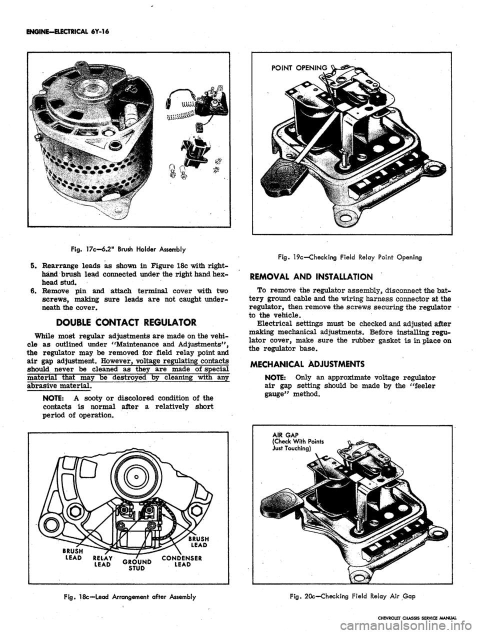
5. Rearrange leads as shown in Figure 18c with right-
hand brush lead connected under the right hand hex-
head stud.
6. Remove pin and attach terminal cover with two
screws, making sure leads are not caught under-
neath the cover.
DOUBLE CONTACT REGULATOR
While most regular adjustments are made on the vehi-
cle as outlined under "Maintenance and Adjustments",
the regulator may be removed for field relay point and
air gap adjustment. However, voltage regulating contacts
should never be cleaned as they are made of special
material that may be destroyed by cleaning with any
abrasive material.
NOTE:
A sooty or discolored condition of the
contacts is normal after a relatively short
period of operation.
Fig. 19c—Checking Field Relay Point Opening
REMOVAL AND INSTALLATION
To remove the regulator assembly, disconnect the bat-
tery ground cable and the wiring harness connector at the
regulator, then remove the screws securing the regulator
to the vehicle.
Electrical settings must be checked and adjusted after
making mechanical adjustments. Before installing regu-
lator cover, make sure the rubber gasket is in place on
the regulator base.
MECHANICAL ADJUSTMENTS
NOTE:
Only an approximate voltage regulator
air gap setting should be made by the "feeler
gauge" method.
BRUSH
LEAD
BRUSH
LEAD
RELAY
^B-/lliLlK
CONDENSER
LEAD
GROUND
LEAD
STUD
AIR GAP
(Check
With
Points
Just
Touching)
Fig.
18c—Lead
Arrangement
after
Assembly
Fig. 20c—Checking Field Relay Air Gap
CHEVROLET CHASSIS SERVICE MANUAL
Page 342 of 659
ENGINE-ELECTRICAL 6Y-17
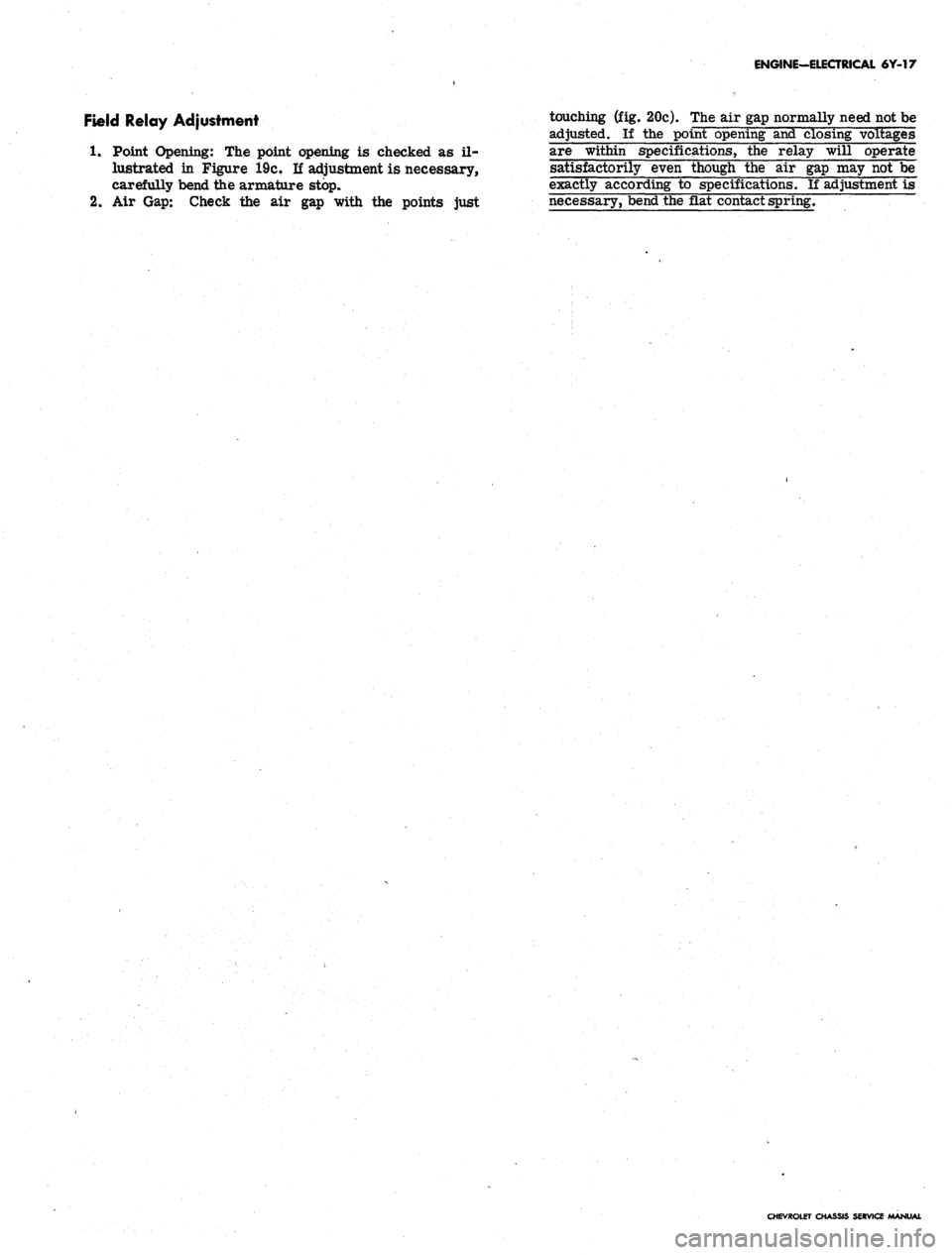
Field Relay Adjustment touching (fig. 20c). The air gap normally need not be
adjusted. If the point opening and closing voltages
1.
Point Opening: The point opening is checked as il- are within specifications, the relay will operate
lustrated in Figure 19c. If adjustment is necessary, satisfactorily even though the air gap may not be
carefully bend the armature stop. exactly according to specifications. If adjustment is
2.
Air Gap: Check the air gap with the points just necessary, bend the flat contact spring.
CHEVROLET CHASSIS SERVICE MANUAL