relay CHEVROLET CAMARO 1967 1.G Chassis Service Manual
[x] Cancel search | Manufacturer: CHEVROLET, Model Year: 1967, Model line: CAMARO, Model: CHEVROLET CAMARO 1967 1.GPages: 659, PDF Size: 114.24 MB
Page 474 of 659
STEERING 9-34
Fig.
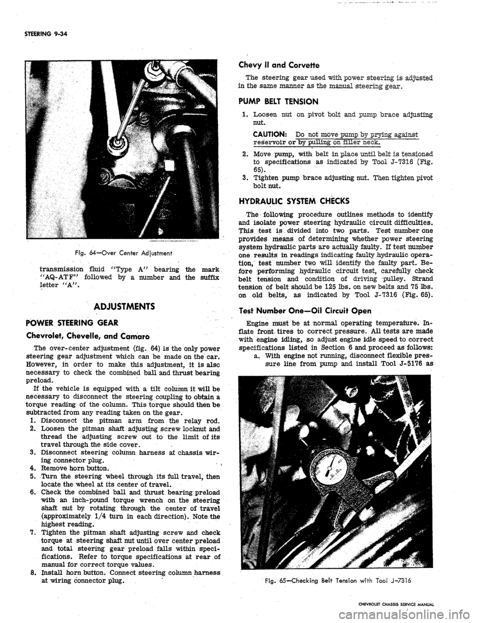
64-Over Center Adjustment
transmission fluid "Type A" bearing the mark
"AQ-ATF" followed by a number and the suffix
letter "A".
ADJUSTMENTS
POWER STEERING GEAR
Chevrolet, Chevelle, and Camaro
The over-center adjustment (fig. 64) is the only power
steering gear adjustment which can be made on the car.
However, in order to make this adjustment, it is also
necessary to check the combined ball and thrust bearing
preload.
If the vehicle is equipped with a tilt column it will be
necessary to disconnect the steering coupling to obtain a
torque reading of the column. This torque should then be
subtracted from any reading taken on the gear.
1.
Disconnect the pitman arm from the relay rod.
2.
Loosen the pitman shaft adjusting screw loeknut and
thread the adjusting screw out to the limit of its
travel through the side cover. '. •
3.
Disconnect steering column harness at chassis wir-
ing connector plug.
4.
Remove horn button.
5.
Turn the steering wheel through its full travel, then
locate the wheel at its center of travel.
6. Gheck the combined ball and thrust bearing preload
with an inch-pound torque wrench on the steering
shaft nut by rotating through the center of travel
(approximately 1/4 turn in each direction). Note the
highest reading.
7.
Tighten the pitman shaft adjusting screw and check
torque at steering shaft nut until over center preload
and total steering gear preload falls within speci-
fications. Refer to torque specifications at rear of
manual for correct torque values.
8. Install horn button. Connect steering column harness
at wiring connector plug.
Chevy II and Corvette
The steering gear used with power steering is adjusted
in the same manner as the manual steering gear.
PUMP BELT TENSION
1.
Loosen nut on pivot bolt and pump brace adjusting
nut.
CAUTION: Do not move pump by prying against
reservoir or by pulling on filler neck.
2.
Move pump, with belt in place until belt is tensioned
to specifications as indicated by Tool J-7316 (Fig-.
65).
3.
Tighten pump brace adjusting nut. Then tighten pivot
bolt nut.
HYDRAULIC SYSTEM CHECKS
The following procedure outlines methods to identify
and isolate power steering hydraulic circuit difficulties.
This test is divided into two parts. Test number one
provides means of determining whether power steering
system hydraulic parts are actually faulty. If test number
one results in readings indicating faulty hydraulic opera-
tion, test number two will identify the faulty part. Be-
fore performing hydraulic circuit test, carefully check
belt tension and condition of driving pulley. Strand
tension of belt should be 125 lbs. on new belts and 75 lbs.
on old belts, as indicated by Tool J-7316 (Fig. 65).
Test Number One—Oil Circuit Open
Engine must be at normal operating temperature. In-
flate front, tires to correct pressure. All tests are made
with engine idling, so adjust engine idle speed to correct
specifications listed in Section 6 and proceed as follows:
a. With engine not running, disconnect flexible pres-
sure line from pump and install Tool J-5176 as
Fig.
65— Checking Belt Tension with Tool J-7316
CHEVROLET CHASSIS SERVICE MANUAL
Page 477 of 659
STEERING 9-37
NUT
Fig.
69—Control Valve Ball Stud Seal Replacement
(Service Type)
4.
Center the ball stud, seal and clamp at opening in
adapter housing, then install spacer, bolt and nut.
Removal
1.
Raise the front of the vehicle off the floor and place
it on stands.
2.
Remove the relay rod to control valve clamp bolt.
3.
Disconnect the two pump to control valve hose cdn-
nections and allow fluid to drain into a container,
then disconnect the two remaining valve to power
cylinder hoses.
4.
Remove the retaining nut from the ball stud to pitman
arm connection and disconnect the control valve
from the pitman arm.
5. Turn the pitman arm to the right clear of the control
valve and unscrew the control valve from the relay
rod.
6. Remove the control valve from the vehicle.
Installation
1.
Install the control valve on the vehicle by reversing
the removal procedure.
2.
Reconnect the hydraulic lines, fill the system with
fluid and bleed out air using the procedure outlined
under "Maintenance and Adjustments/' Grease ball
joint.
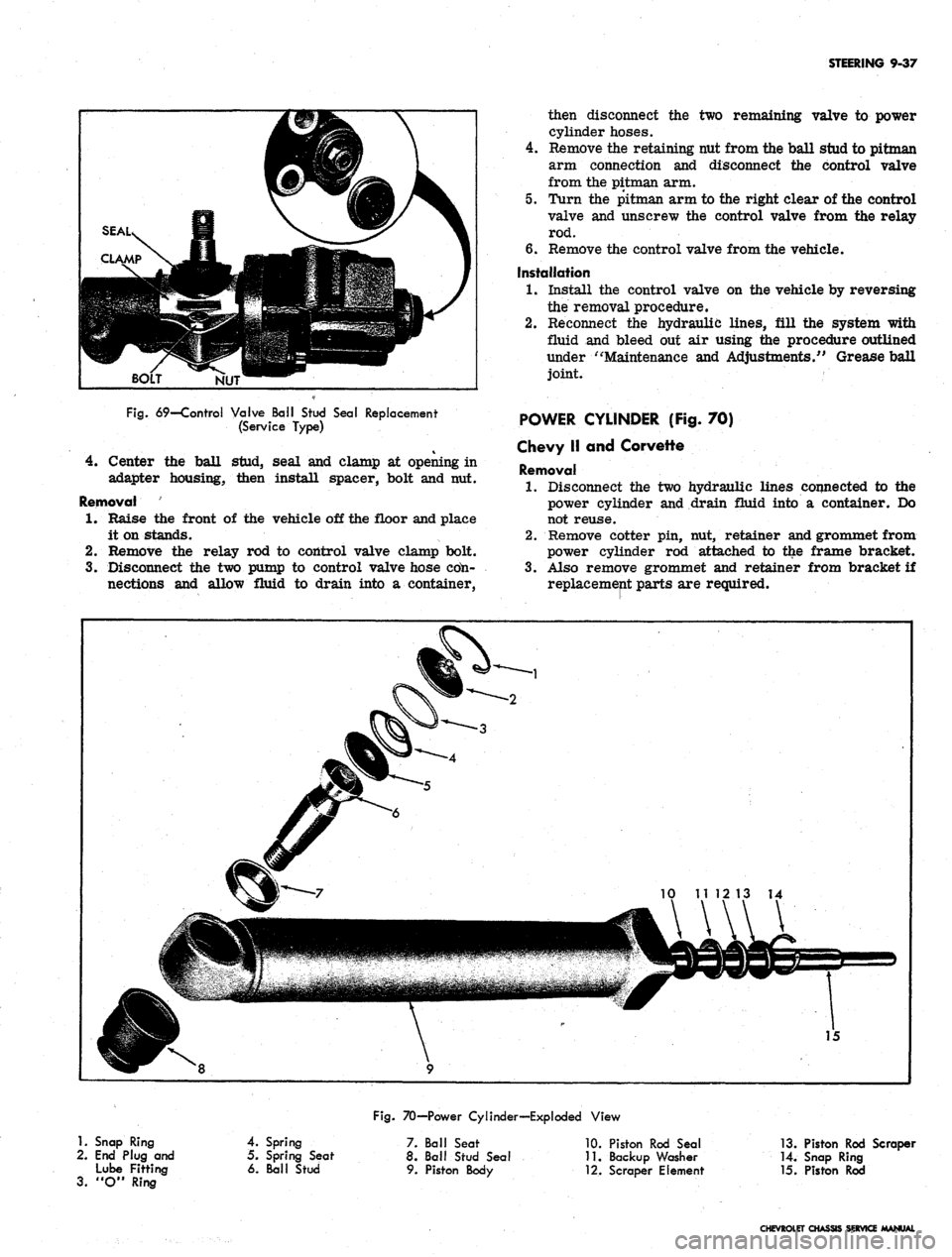
POWER CYLINDER (Fig. 70)
Chevy II and Corvette
Removal
1.
Disconnect the two hydraulic lines connected to the
power cylinder and drain fluid into a container. Do
not reuse.
2.
Remove cotter pin, nut, retainer and grommet from
power cylinder rod attached to the frame bracket.
3.
Also remove grommet and retainer from bracket if
replacement parts are required.
1.
Snap Ring
2.
End Plug and
Lube Fitting
3.
"O" Ring
Fig.
70—Power Cylinder—Exploded View
4.
Spring
5. Spring Seat
6. Ball Stud
7. Ball Seat
8. Ball Stud Seal
9. Piston Body
10.
Piston Rod Seal
11.
Backup Washer
•12.
Scraper Element
13.
Piston Rod Scraper
14.
Snap Ring
15.
Piston Rod
CHEVROLET CHASSIS SERVICE MANUAL
Page 479 of 659
STEERING 9-39
4.
Remove cotter pin, nut and ball stud at relay rod.
5. Remove the power cylinder from the vehicle.
Inspection
1.
Inspect the seals for leaks; if leaks are present,
replace the seals using the procedure outlined under
"Disassembly."
2.
Examine the brass fitted hose connection seats for
cracks or damage and replace if necessary.
3.
For service other than ball seat or seal replacement
and ball stud removal, replace the power cylinder.
4.
Check the frame bracket parts for wear.
Disassembly
1.
To remove the piston rod seal remove the snap ring;
then pull out on the rod, being careful not to spray
oil.
2.
Remove the piston rod scraper and scraper element,
back up washer and piston rod seal from the rod.
3.
At the ball stud end of the cylinder, remove the ball
stud seal.
4.
Remove the snap ring retaining the end plug with the
lube fitting.
5. Push on the end of the ball stud and remove the end
plug, spring, spring seat and ball stud.
6. Remove the "O" ring seal from the top lip of the
power cylinder ball stud opening.
7. If the ball seat is to be replaced, it must be pressed
out using Tool J-8937.
Assembly
1.
Reassemble the piston rod seal components by re-
versing the disassembly procedure. Apply a thin
coat of Lubriplate or equivalent on the inner sur-
faces of the seal and scraper before assembly.
2.
Reverse the disassembly procedure when reassem-
bling the ball stud.
3.
In each case be sure that the snap ring is securely,
seated in the ring groove.
Installation
1.
Install the power cylinder on the vehicle by reversing
the removal procedure.
2.
Reconnect the two hydraulic lines, fill the system
with fluid and bleed out air using the procedure out-
lined under "Maintenance and Adjustments." Grease
ball joint.
POWER STEERING HOSES
When servicing the power steering hoses be sure to
align the hoses in their correct position as shown in
Figure 71. On Chevelle models with 396 engine, install
the upper hose so that there is at least .6 inch clearance
between the hose and the Delcotron or the inner fender
skirt.
It is important that the power steering hoses be in-
stalled correctly. Hoses installed out of position may be
subjected to chafing or other abuses during sharp turns.
Always make hose installations with front wheels in
straight ahead position. Do not twist hoses unneces-
sarily during installation.
CAUTION: Do not start engine with any power
steering hose disconnected.
CHEVROLET CHASSIS SERVICE MANUAL
Page 501 of 659
CHASSIS SHEET METAL 11-14
location is shimmed; thus keeping the fender mount-
ing bolts from crushing in the fender mounting
flange.
If shimming is done without the fenders being disas-
asembled, it is suggested that fender mounting bolts
rearward of radiator support be loosened while shims
are inserted and sheet metal fit is checked. Tighten
shimmed mounting bolts first, then all others.
COMPONENT PART REPLACEMENT
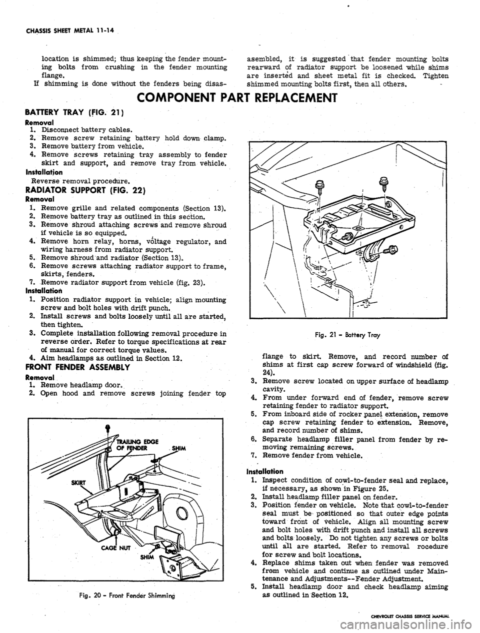
BATTERY TRAY (FIG. 21)
Removal
1.
Disconnect battery cables.
2.
Remove screw retaining battery hold down clamp.
3.
Remove battery from vehicle.
4.
Remove screws retaining tray assembly to fender
skirt and support, and remove tray from vehicle.
Installation
Reverse removal procedure.
RADIATOR SUPPORT (FIG. 22)
Removal
1.
Remove grille and related components (Section 13).
Remove battery tray as outlined in this section.
Remove shroud attaching screws and remove shroud
if vehicle is so equipped.
Remove horn relay, horns, voltage regulator, and
wiring harness from radiator support.
Remove shroud and radiator (Section 13)o
Remove screws attaching radiator support to frame,
skirts,
fenders.
Remove radiator support from vehicle (fig. 23).
Installation
1.
Position radiator support in vehicle; align mounting
screw and bolt holes with drift punch.
Install screws and bolts loosely until all are started,
then tighten.
3.
Complete installation following removal procedure in
reverse order. Refer to torque specifications at rear
of manual for correct torque values.
4.
Aim headlamps as outlined in Section 12.
FRONT FENDER ASSEMBLY
Removal
1*
Remove headlamp dooro
2.
Open hood and remove screws joining fender top
2.
Fig. 20 - Front Fender Shimming
Fig.
21 - Battery Tray
flange to skirt. Remove, and record number of
shims at first cap screw forward of windshield (fig.
24).
3.
Remove screw located on upper surface of headlamp
cavity.
4.
From under forward end of fender, remove screw
retaining fender to radiator support.
5.
From inboard side of rocker panel extension, remove
cap screw retaining fender to extension. Remove,
and record number of shims.
6. Separate headlamp filler panel from fender by re-
moving remaining screws.
7.
Remove fender from vehicle.
Installation
1.
Inspect condition of cowl-to-fender seal and replace,
if necessary, as shown in Figure 25.
2.
Install headlamp filler panel on fender.
3.
Position fender on vehicle. Note that eowl-to-fender
seal must be positioned so that outer edge points
toward front of vehicle. Align all mounting screw
and bolt holes with drift punch and install all screws
and bolts loosely. Do not tighten any screws or bolts
until all are started. Refer to removal rocedure
for screw and bolt locations.
4.
Replace shims taken out when fender was removed
from vehicle and continue as outlined under Main-
tenance and Adjustments—Fender Adjustment.
5.
Install headlamp door and cheek headlamp aiming
as outlined in Section 12.
CHEVROLET CHASSIS SERVICE MANUAL
Page 507 of 659

CHASSIS SHEET METAL 11-20
GENERAL DESCRIPTION
The Camaro sheet metal components are much the
same as other Chevrolet passenger models as shown in
Figure 32. The front end design is such that servicing
of the fenders and skirts is most efficiently performed
by removing the fender and skirt as an assembly. Refer
to Section 14 for bumper service procedures, Section 13
for radiator and grille, and Section 1A for air condition-
ing components.
MAINTENANCE AND ADJUSTMENTS
HOOD ADJUSTMENT
The Camaro hood is adjusted in the conventional man-
ner, by adjustment of the hood bumpers and hinges. The
two hood bumpers are located on each side at the top of
the radiator support. Do not attempt hood latch adjust-
ments until the hinges and bumpers are correctly ad-
justed. Latch adjustments are made so that effort re-
quired to open and close the hood is reasonable, and
hood alignment obtained by hinge and bumper adjust-
ment is maintained when the hood is closed. Note that
the hood latch is not designed to correct basic hood mis-
alignment.
HOOD HINGE (Fig. 33)
NOTE: The body mounted portion of the hood
hinges are slotted to provide up and down move-
ment. The hood mounted end is slotted to pro-
vide forward and rearward movement.
1.
Scribe a. line around the entire. hinge plate to be
repositioned.
2.
Loosen the appropriate screws and shift the position
of the hood into correct alignment using the scribe
marks to check amount of movement. Check align-
ment by tightening screws and closing the hood.
HOOD BUMPERS
Adjust hood bumpers so that hood top surface is flush
with fender and header panel top surfaces. See Figure
34 for correct sheet metal adjustment dimensions.
HOOD CATCH AND LOCK (Fig. 35)
Adjust hood lock bolt so that top surface of hood is
flush with top surface'of header panel. The distance that
the lock bolt protrudes out of the lock plate should be
adjusted so that the hood bumpers are slightly com-
pressed by the fully latched hood, and effort required
to release the hood catch is reasonable. Close the hood
and insure catch engages securely.
FENDERS
Fenders are adjustable with shims at the cowl and
rocker panel. To add or remove shims, loosen bolts
Fig. 33 - Hood Hinge - Camaro
at shim locations (fig. 36) and carefully apply force with
pry bar to provide clearance for shim removal or in-
stallation.
SHEET METAL
For proper operation of doors and hood, and for pre-
sentable appearance, adjust front sheet metal to the di-
mensions shown in Figure 34.
COMPONENT PART REPLACEMENT
NOTE: When replacing sheet metal compo-
nents on Camaro, note position and attachment
of all seals and dust shielding and replace if
necessary.
BATTERY TRAY
Removal
1.
Disconnect battery cables and remove battery from
vehicle.
2.
Remove screws securing battery tray to fender skirt
and radiator support.
3.
Remove battery tray from vehicle.
Installation
Install battery tray following removal procedure in
reverse order.
RADIATOR SUPPORT
Removal
1.
Raise hood, disconnect battery cables, and remove
battery.
2.
Remove front bumper (Section 14).
3.
Remove grille and related components (Section 13).
4.
Disconnect horns, horn relay, voltage regulator,
CHEVROLET CHASSIS SERVICE MANUAL
Page 514 of 659
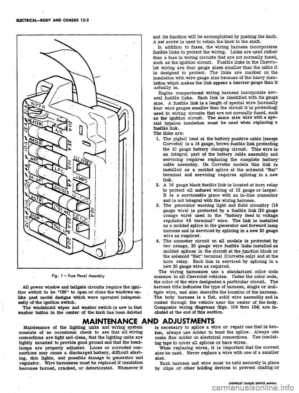
ELECTRICAL-BODY AND CHASSIS 12-2
FJg.
1 - Fuse Panel Assembly
All power window and tailgate circuits require the igni-
tion switch to be "ON" to open or close the windows un-
like past model designs which were operated independ-
ently of the ignition switch.
The windshield wiper and washer switch is new in that
washer button in the center of the knob has been deleted
and its function will be accomplished by pushing the knob.
A set screw is used to retain the knob to the shaft.
In addition to fuses, the wiring harness incorporates
fusible links to protect the wiring. Links are used rather
than a fuse in wiring circuits that are not normally fused,
such as the ignition circuit. Fusible links in the Chevro-
let wiring are four gauge sizes smaller than the cable it
is designed to protect. The links are marked on the
insulation with wire gauge size because of the heavy insu-
lation which makes the link appear a heavier gauge than it
actually is.
Engine compartment wiring harness incorporate sev-
eral fusible links. Each link is identified with its gauge
size.
A fusible link is a length of special wire (normally
four wire gauges smaller than the circuit it is protecting)
used in wiring circuits that are not normally fused, such
as the ignition circuit. The same size wire with a spe-
cial hypalon insulation must be used when replacing a
fusible link.
The links are:
1.
The pigtail lead at the battery positive cable (except
Corvette) is a 14 gauge, brown fusible link protecting
the 10 gange battery charging circuit. This wire is
an integral part of the battery cable assembly and
servicing requires replacing the complete battery
cable assembly. On Corvette models this link is
installed as a molded splice at the solenoid "Bat"
terminal and servicing requires splicing in a new
link.
2.
A 16 gauge black fusible link is located at horn relay
to protect all unfused wiring of 12 gauge or larger.
It is a serviceable piece with an in-line connector
and is not integral with the wiring harness.
3.
The generator warning light and field circuitry (16
gauge wire) is protected by a fusible link (20 gauge
orange wire) used in the "battery feed to voltage
regulator #3 terminal" wire. The link is installed
as a molded splice in the generator and forward lamp
harness and is serviced by splicing in a new 20 gauge
wire as required.
4.
The ammeter circuit on all models is protected by
two orange, 20 gauge wire fusible links installed as
molded splices in the circuit at the junction block or
the solenoid "Bat" terminal (Corvette only) and at the
horn relay. Each link is serviced by splicing in a
new 20 gauge wire as required.
The wiring harnesses use a standarized. color code
common to all Chevrolet vehicles. Under the color code,
the color of the wire designates a particular circuit. The
harness title indicates the type of harness, single of mul-
tiple wire, and also describe the location of the harness.
The body harness is a flat, solid wire assembly and is
routed through the vehicle near the center of the body.
Composite wiring diagrams (figs. 104 thru 124) are in-
cluded at the end of this section.
MAINTENANCE AND ADJUSTMENTS
Maintenance of the lighting units and wiring system
consists of an occasional check to see that all wiring
connections are tight and clean, that the lighting units are
tightly mounted to provide good ground and that the head-
lamps are properly adjusted. Loose or corroded con-
nections may cause a discharged battery, difficult start-
ing, dim lights, and possible damage to generator and
regulator. Wire harnesses must be replaced if insulation
becomes burned, cracked, or deteriorated. Whenever it
is necessary to splice a wire or repair one that is bro-
ken, always use solder to bond the splice. Always use
rosin flux solder on electrical connections. Use insulat-
ing tape to cover all splices or bare wires.
When replacing wires, it is important that the correct
size be used. Never replace a wire with one of a smaller
size.
Each harness and wire must be held securely in place
by clips or other holding devices to prevent chafing or
CHEVROLET CHASSIS SERVICE MANUAL
Page 560 of 659
ELECTRICAL-BODY
AND CHASSIS 12-48
NOTE:
Screws, nuts and lock washers for re-
assembling cover to wiper are contained in a
service repair package.
6. Remove output gear and shaft assembly, then slide
,
intermediate gear and pinion assembly off shaft.
7. If necessary, remove terminal board and park switch
assembly as follows:
a. Unsolder motor leads from terminals. Coding of
motor leads is not necessary on single-speed
wipers.
b.
Drill out rivets securing terminal board and park
switch ground strap to mounting plate.
NOTE:
Screws, nuts and washers for attaching
a replacement terminal board-park switch as-
sembly are included with the replacement
assembly.
Motor
(Fig. 65)
1.
Follow Steps 1 through 7b under gear box
disassembly.
2.
Remove, motor through bolts, tap motor frame
lightly, and remove motor from mounting plate.
3.
Remove brush spring tension (fig. 68), slide arma-
ture and end plate from motor frame. Pull end
plate from armature.
NOTE:
Thrust plug located between armature
shaft and end plate.
4.
Remove end play adjusting washers from armature,
noting arrangement for proper reinstallation.
INSPECTION
Check and inspect all parts for serviceability, replace
as necessary. All parts can be replaced individually
except motor frame and field, which is serviced as an
assembly. Service kits also provide screws, nuts and
washers to replace gear cpver and terminal board rivets.
ASSEMBLY
Refer to Figure 65 for exploded view of motor and gear
train.
Motor
Reassemble motor using reverse of disassembly
procedures.
NOTE:
Armature end play is controlled by end
play washers. See Figure 69 for proper assem-
bly of end play washers. Lubricate armature
shaft bushings with light machine oil.
Gear Box
1.
Assemble gear box using reverse of disassembly
procedure.
NOTE:
Lubricate gear teeth with Delco Cam
and Ball Bearing lubricant or equivalent. Be
sure cover is properly located over dowel pins
and be sure to reinstall ground strap.
2.
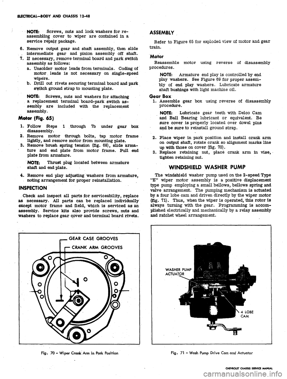
Place wiper in park position and install crank arm
on output shaft, rotate crank so alignment marks line
up with those on cover (fig. 70).
3.
Replace retaining nut, place crank arm in vise,
tighten retaining nut.
WINDSHIELD
WASHER PUMP
The windshield washer pump used on the 2-speed Type
"E"
wiper motor assembly is a positive displacement
type pump employing a small bellows, bellows spring and
valve arrangement. The pumping mechanism is actuated
by a four lobe cam and driven directly by the wiper motor
(fig. 71). Thus, when the wiper is operated, this rotor is
always turning with the gear. Programming is accom-
plished electrically and mechanically by a relay assembly
and ratchet wheel arrangement.
GEAR
CASE GROOVES
r— CRANK ARM GROOVES
WASHER PUMP
Ha
ACTUATOR
IB
•
^^HTS4LOBE
•MMBW
CAM
Fig.
70 - Wiper Crank Arm in Park Position
Fig.
71 - Wash Pump Drive Cam and Actuator
CHEVROLET
CHASSIS SERVICE MANUAL
Page 561 of 659

ELECTRICAL-BODY
AND
CHASSIS
12-49
BELLOWS
AND
SPRING
HOUSING
COIL
AND
POLE
ASSEMBLY
VALVE
ASSEMBLY
RATCHET
PAWL
ASSEMBLY
RATCHET
WHEEL
ACTUATOR
PLUNGER
ARM
ACTUATOR
PIN
HOLDING CONTACTS
OPEN
RAMP TANG
PLUNGER
ARM
Fig.
73 -
Releasing
Pump from
Lockout Position
Fig.
72 -
Washer
Pump
Mechanism
REMOVAL AND INSTALLATION
Removal of the washer pump from the wiper motor
consists of:
1.
Disconnect wiring harness and washer hoses from
washer.
2.
Remove the two pump-to-wiper retaining screws and
remove washer from wiper (fig. 66).
3.
Reverse removal procedure to install assembly.
DISASSEMBLY-ASSEMBLY
Refer to Figure
1.
Remove washer pump cover.
2.
Relay
a. To remove relay unsolder coil leads from
terminals.
NOTE:
No coil polarity is necessary when re-
soldering coil leads.
b.
Remove coil retainer clip and slip coil assembly
out of mounting bracket.
3.
Ratchet Pawl
a. To remove ratchet pawl disengage spring from
ratchet pawl and slide ratchet pawl from shaft.
CAUTION: Be sure spring is properly assem-
bled before replacing washer pump cover.
Terminal Board
a. Remove terminal board attaching screws, ratchet
dog and board from washer base.
Ratchet Wheel
a. Remove lock ring from shaft.
b.
Slide ratchet wheel from shaft.
Valve Assembly
a. To remove valve assembly remove screws that
secure valve assembly to bellows housing.
CAUTION: It may be necessary to carefully
pry bellows lip out of the valve body groove.
Bellows
a. To remove bellows first remove valve assembly.
b.
Manually operate pump clockwise to release pump
from 'lock-out" position (fig, 73).
c. Hold bellows plunger arm from moving, then push
in against bottom of bellows with thumb and twist
bellows spring from housing.
Actuator Pin
a. Remove actuator pin retaining spring and slide
pin from washer base.
Reverse disassembly procedure to assemble washer.
DEPRESSED PARK 2-SPEED WIPER
CHEVROLET
GENERAL DESCRIPTION
The Type "C" two speed electric wiper assembly (fig.
74) incorporates a depressed park type (blades park
against windshield lower molding when the motor is
turned off) motor and gear train. The wiper has a com-
pound wound 12 volt motor and a gear box section con-
taining the gear mechanism and relay control. The motor
armature is fitted with a worm gear which drives the
main gear assembly and crank arm.
The relay control, consisting of a relay coil, relay
armature and switch assembly, is located in the gear box
section bid controls the starting and stopping of the wiper
through a latching mechanism (fig. 75).
An electric washer pump is mounted on the gear box
section of the wiper and is driven by the wiper unit gear
assembly (fig* 75).
The overhaul procedures for the wiper are broken down
into three major areas: The motor section, gear box
section and washer pump section. Each section maybe
serviced independently of the other.
CHEVROLET CHASSIS SEftVKX
Page 562 of 659

ELECTRICAL-BODY AND CHASSIS 12-50
SERVICE OPERATIONS
MOTOR SECTION
DISASSEMBLY
NOTE:
Motor section
may be
disassembled
independently
of
the gear box.
Brush Plate and Circuit Breaker Removal
1.
Scribe
a
reference line along the side of the casting
and end cap to insure proper re-assembly.
2.
Remove the two motor thru bolts.
3.
Feed exposed excess length
of
motor leads thru the
casting grommet
and
carefully back
the
case
and
field assembly plus
the
armature away from
the
casting (fig. 76).
NOTE:
It may be
necessary
to
remove
the
armature end play adjusting screw and insert
a
rod thru
the
opening
in
order to apply pressure
against the end of the armature.
4.
Unsolder
the
black lead from circuit breaker
(fig.
77).
5.
Straighten
out the 4
tabs that secure the brush plate
to the field coil retainers (fig. 77).
CAUTION:
Be
careful
not to
break
any of
the
retainer tabs.
6. Install
"U"
shaped brush retainer clip over brush
holder that has brush lead attached to circuit breaker
(fig. 78).
7.
Holding
the
opposite brush from that retained in Step
6, carefully lift
the
brush holder
off the
mounting
tabs
far
enough
to
clear
the
armature commutator
(fig. 78).
8. Allow
the
brush, held
in
Step
7, to
move out
of its
holder. Remove
the
brush spring
and
lift the brush
holder
off
the armature shaft.
Armature Removal
1.
Follow Steps
1
thru
8
under brush plate removal.
2.
Lift armature out
of
case and field assembly.
3.
Remove thrust ball from
end of
armature shaft
as
PUMP
ASSEMBLY
CAM SLOT
DRIVE PLATE
AND
ASSEMBLY
RELAY SWITCH
ASSEMBLY
WASHER PUMP
DRIVE
PIN
Fig.
75
-
Wiper and Washer
Pump
Mechanism
required and save
for
reassembly.
NOTE: Thrust ball
may be
easily removed
with
a
magnet.
MOUNTING
GROMMET
WASHER PUMP COVER
RETAINING RING
STAKE MARKS -
CASE
TO
FIELD
LAMINA
(4
PLACES)
Fig. 74 - Depressed Park 2-Speed Wiper
Fig. 76 - Wiper Motor Separation
CHEVROLET CHASSIS SERVICE MANUAL
Page 563 of 659

ELECTRICAL-BODY
AND
CHASSIS
12-51
7^5
CUT MOTOR LEADS
GENERALAREA
FOR
in|i
BRUSH PLATE
ASSEMBIYI^^H
RETAINER TAB (4)__J^^H
BLACK
LEAD
TO §HH
CIRCUIT BREAKER»^^—
CIRCUIT
F^H^^^^^B
BREAKER)
^^SH^P
IN
THIS
m
•I
i
ii
ii ii H^MWii^A'
I^BRT^i"
BRUSH
•^^k RETAINER CLIP
•
SPUCENOTES:
•
1-SOLID
BLACK
TO
•
SHUNT FIELD COIL
5
2-SERIES
FIELD COIL
I
TO
BLACK WITH PINK
H STRIPE LEAD
w
Fig.
77
-
Circuit Breaker
Case and Field Assembly Removal
1.
Remove brush plate and armature.
2.
The end
case
and
field assembly
is
serviced
as
a
DRIVE PLATE
&*
ASSEMBLY
DRIVE PAWL
IN
PARK POSITION
IN
RELAY SWITCH SLOT
RELAY SWITCH ASSEMBLY
Fig.
79-
Drive Pawl
in
Full Park Position
unit.
To
free
the
field
and
case assembly,
cut the
solid black and black with pink stripe leads
in a
lo-
cation convenient
for
splicing
-
preferably near
the
wiper terminal board. Refer to Figure
76.
Remove steel thrust plate and rubber disc from case
bearing
as
required.
DRIVE
PAWL
ENGAGING
LATCH
ARM
Fig.
78
-
Removing Brush Holder
Fig.
80
-
Relay Assembly
CHEVROLET
CHASSIS SERVICE MANUAL