tow CHEVROLET CAMARO 1967 1.G Chassis Owner's Guide
[x] Cancel search | Manufacturer: CHEVROLET, Model Year: 1967, Model line: CAMARO, Model: CHEVROLET CAMARO 1967 1.GPages: 659, PDF Size: 114.24 MB
Page 209 of 659
REAR SUSPENSION
AND
DRIVE LINE
4-19
BRAKE BRAKE
DISC SHOE
OUTER
BEARII
-. -,
-«#*;>•
BRAKE
CAMPER
/
/ /
/ /
si—a
wC—
SPINDLE
^ SUPPOR1
BEARING
^ SPACER
INNER
" BEARING
DRIVE
" FLANGE
BEARING
-PRELOAD
SPACER
DEFLECTOR
CONTROL
ARM
Fig.
46-Wheel Spindle
and
Support Cross-Section (Corvette)
assembly is installed.
d. Pack outer bearing with a high-melting point
wheel bearing lubricant and position on spindle.
Large end of bearing should be toward shoulder
on spindle.
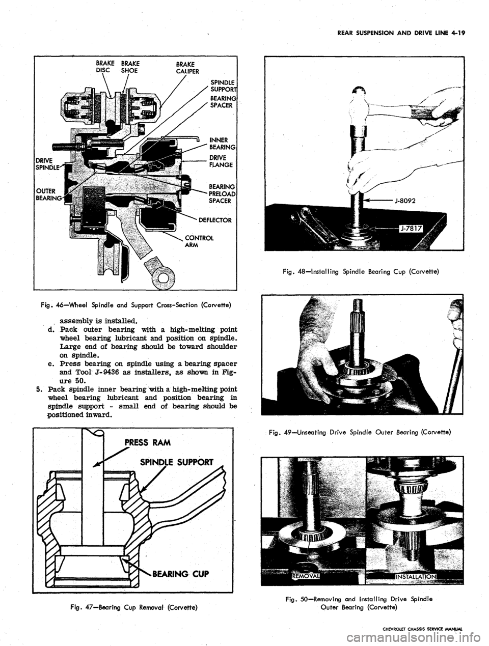
e. Press bearing on spindle using a bearing spacer
and Tool J-9436 as installers, as shown in Fig-
ure 50.
5. Pack spindle inner bearing with a high-melting point
-wheel bearing lubricant and position bearing in
spindle support - small end of bearing should be
positioned inward.
PRESS RAM
BEARING CUP
Fig.
48—Installing Spindle Bearing Cup (Corvette)
Fig.
49—Unseating Drive Spindle Outer Bearing (Corvette)
Fig.
47—Bearing Cup Removal (Corvette)
Fig.
50—Removing and Installing Drive Spindle
Outer Bearing (Corvette)
CHEVROLET CHASSIS SERVICE MANUAL
Page 210 of 659
REAR SUSPENSION AND DRIVE LINE 4-20
Fig.
51—Shock Absorber Installation (Corvette)
6. Tap new spindle inner grease seal into seal bore
and install deflector over support inner end.
Installation
1.
Position support over torque arm bolts with strut
rod fork toward center of vehicle and downward.
Place backing plate over studs and torque nuts to
specifications.
2.
Connect parking brake cable to actuating lever.
3.
Install drive spindle assembly as outlined previously
in this section under "Wheel Bearing Adjustment".
4.
If new spindle support or associated parts are in-
stalled, determine correct shim size as follows.
a. Assemble spindle to support, using a .145" shim.
b.
Check bearing adjustment and correct as neces-
sary, following adjustment procedures previously
outlined.
DIFFERENTIAL CARRIER SUPPORT
BRACKET REPLACEMENT
1.
Place a 1/2" thick block of wood or steel between
nose of differential carrier and floor pan. This will
prevent carrier from twisting upward when support
bracket is disconnected.
2.
Remove carrier support-to-crossmember attaching
bolt.
3.
Remove nut from both of the bracket-to-carrier
through bolts.
4.
Slide bolts to one side until bolt head contacts floor
well. Mark the floor well at this point and drill a
3/4"
diameter hole for each bolt in floor well and
remove bolts.
5. Assemble carrier support bracket by reversing
above procedure. Torque all affected parts to
specifications.
6. Insert plastic plugs from the inside of the floor well
holes to prevent dust and water entry.
STRUT ROD SHAFT STRUT ROD
CAMBER CAM
AND BOLT
Fig.
52—Strut Rods (Corvette)
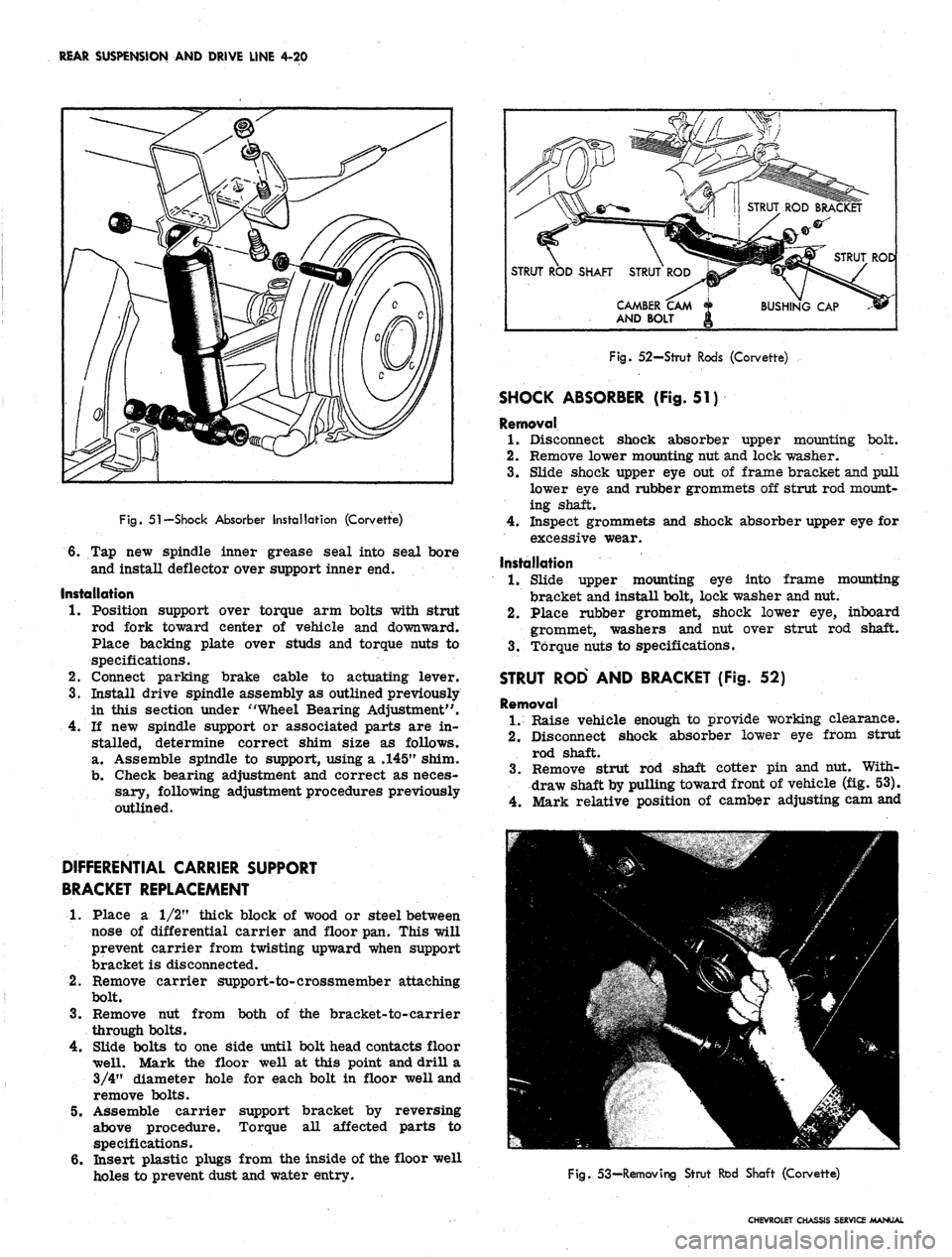
SHOCK ABSORBER (Fig. 51)
Removal
1.
Disconnect shock absorber upper mounting bolt*
2.
Remove lower mounting nut and lock washer.
3.
Slide shock upper eye out of frame bracket and pull
lower eye and rubber grommets off strut rod mount-
ing shaft.
4.
Inspect grommets and shock absorber upper eye for
excessive wear.
Installation
1.
Slide upper mounting eye into frame mounting
bracket and install bolt, lock washer and nut.
2.
Place rubber grommet, shock lower eye, inboard
grommet, washers and nut over strut rod shaft.
3.
Torque nuts to specifications.
STRUT ROD AND BRACKET (Fig. 52)
Removal
1.
Raise vehicle enough to provide working clearance.
2.
Disconnect shock absorber lower eye from strut
rod shaft.
3.
Remove strut rod shaft cotter pin and nut. With-
draw shaft by pulling toward front of vehicle (fig. 53).
4.
Mark relative position of camber adjusting cam and
Fig.
53-Removing Strut Rod Shaft (Corvette)
CHEVROLET CHASSIS SERVICE MANUAL
Page 221 of 659
REAR SUSPENSION AND DRIVE LINE 4-31
Fig.
77—Differential Pinion Shaft Removal
AXLE SHAFT
Removal
1.
Raise vehicle to desired working height and remove
wheel and tire assembly and brake drum.
2.
Clean all dirt from area of carrier cover. *
3.
Drain lubricant from carrier by removing cover.
4.
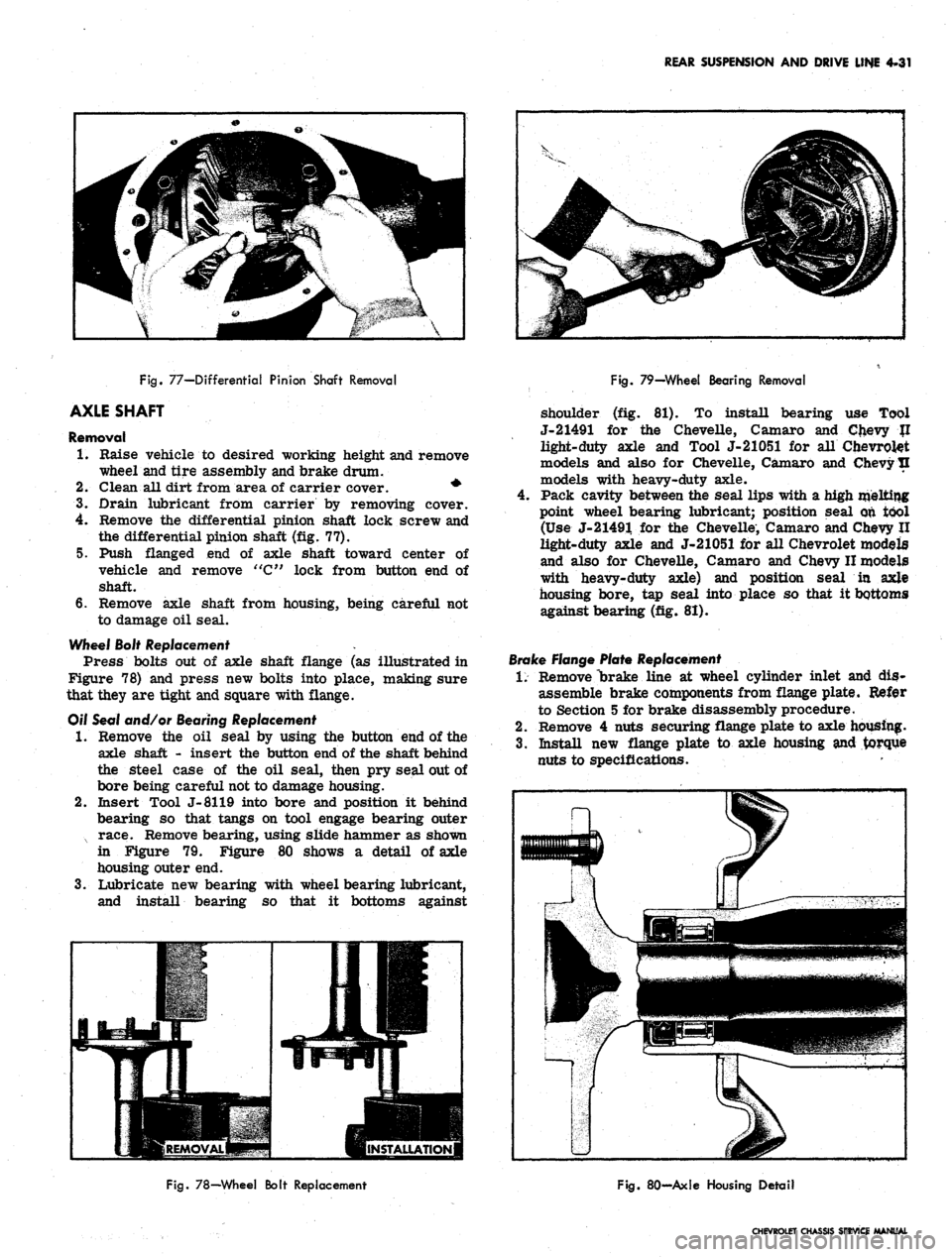
Remove the differential pinion shaft lock screw and
the differential pinion shaft (fig. 77).
5. Push flanged end of axle shaft toward center of
vehicle and remove "C" lock from button end of
shaft.
6. Remove axle shaft from housing, being careful not
to damage oil seal.
Wheel Bolt Replacement .
Press bolts out of axle shaft flange (as illustrated in
Figure 78) and press new bolts into place, making sure
that they are tight and square with flange.
Off Seal and/or Bearing Replacement
•1.
Remove the oil seal by using the button end of the
axle shaft - insert the button end of the shaft behind
the steel case of the oil seal, then pry seal out of
bore being careful not to damage housing.
2.
Insert Tool J-8119 into bore and position it behind
bearing so that tangs on tool engage bearing outer
x race. Remove bearing, using slide hammer as shown
in Figure 79. Figure 80 shows a detail of axle
housing outer end.
3.
Lubricate new bearing with wheel bearing lubricant,
and install bearing so that it bottoms against
Fig.
79—Wheel Bearing Removal
shoulder (fig. 81). To install bearing use Tool
J-21491 for the Chevelle, Camaro and Chevy JI
light-duty axle and Tool J-21051 for all Chevrolet
models and also for Chevelle, Camaro and Chevy tl
models with heavy-duty axle.
Pack cavity between the seal lips with a high melting
point wheel bearing lubricant; position seal on tool
(Use J-21491 for the Chevelle, Camaro and Chevy II
light-duty axle and J-21051 for all Chevrolet models
and also for Chevelle, Camaro and Chevy II models
with heavy-duty axle) and position seal in axle
housing bore, tap seal into place so that it bottoms
against bearing (fig. 81).
Brake Flange Plate Replacement
1.
Remove "brake line at wheel cylinder inlet and dis-
assemble brake components from flange plate. Refer
to Section 5 for brake disassembly procedure.
2.
Remove 4 nuts securing flange plate to axle housing.
3.
Install new flange plate to axle housing and torque
nuts to specifications.
Fig.
78—Wheel Bolt Replacement
Fig.
80-Axle Housing Detail
CHEVROLET CHASSIS SERVICE MANUAL
Page 222 of 659
REAR SUSPENSION AND DRIVE LINE 4-32
HP?
Fig.
81
—Whed Bearing and/or Oil Seal Installation
4.
Install brake components on flange and connect
hydraulic line to wheel cylinder inlet. See Section 5
for brake assembly procedure.
5. Install axle shaft, brake drum and wheel and tire
assembly.
6. Bleed and. adjust brakes as outlined in Section 5.
Installation
1.
Slide axle shaft into place.
CAUTION: Exercise care that splines on end
of shaft do not damage oil seal and that they
engage with splines of differential side gear/
2.
Install axle shaft "C" lock on button end of axle-
shaft and push shaft outward so that shaft lock seats
in counterbore of differential side gear.
3.
Position differential pinion shaft through case and
pinions, aligning hole in shaft with lock screw hole.
Install lock screw and torque to specifications.
4.
Using a new gasket, install carrier cover and torque
bolts to specifications.
CAUTION: Make sure both gasket surfaces on
carrier and cover are clean before installing
new gasket. Torque carrier cover bolts in a
crosswise pattern to ensure uniform draw on
cover gasket.
5. Fill axle with lubricant to a level even with bottom
of filler hole. See Section 0 for proper lubricant.
6. Install brake drum and wheel and tire assembly.
7. Lower vehicle and test operation of axle.
PINION FLANGE, DUST DEFLECTOR
AND/OR OIL SEAL
Replacement
1.
Raise rear of vehicle and place stand jacks under
frame side rails so that axle hangs freely to allow
sufficient working room.
2.
Check wheels for freedom of rotation.
3.
Separate rear universal joint, tape trunnion bearings
to joint, position propeller shaft to one side and tie
it to frame side rail.
4.
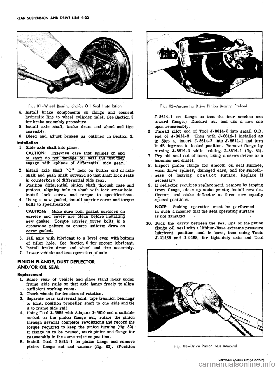
Using Tool J-5853 with Adapter J-5810 and a suitable
socket on the pinion flange nut, rotate the pinion
through several complete revolutions and record the
torque required to keep the pinion turning (fig. 82).
If flange is to be reused, mark pinion and flange for
reassembly in the same relative position.
5. Install Tool J-8614-1 on pinion flange and remove
pinion flange nut and washer (fig. 83). (Position
Fig. 82—Measuring Drive Pinion Bearing Preload
J-8614-1 on flange so that the four notches are
toward flange.) Discard nut and use a new one
upon reassembly.
6. Thread pilot end of Tool J-8614-3 into small O.D.
end of J-8614-2. Then with J-8614-1 installed as
in Step 4, insert J-8614-2 into J-8614-1 and turn
it 45 degrees to locked position. Remove flange by
turning J-8614-3 while holding J-8614-1 (fig. 84).
7. Pry old seal out of bore, using a screw driver or a
hammer and chisel.
8. Inspect pinion flange for smooth oil seal surface,
worn drive splines, damaged ears, and for smooth-
ness of bearing contact surface. Replace if
necessary.
9. If deflector requires replacement, remove by tapping
from flange, clean up stake points; install new de-
flector, and stake deflector at three new equally
spaced positions.
NOTE:
Staking operation must be performed
in such a manner that the seal operating surface
is not damaged.
1.0. Pack the cavity between the seal lips of the pinion
flange oil seal with a lithium-base extreme pressure
lubricant, position seal in bore, then using Tools
J-21468 and J-9458, for light-duty axle and Tool
Fig. 83-—Drive Pinion Nut Removal
CHEVROLET CHASSIS SERVICE MANUAL
Page 224 of 659
REAR SUSPENSION AND DRIVE LINE 4-34
COMPONENT PARTS REPLACEMENT (CORVETTE)
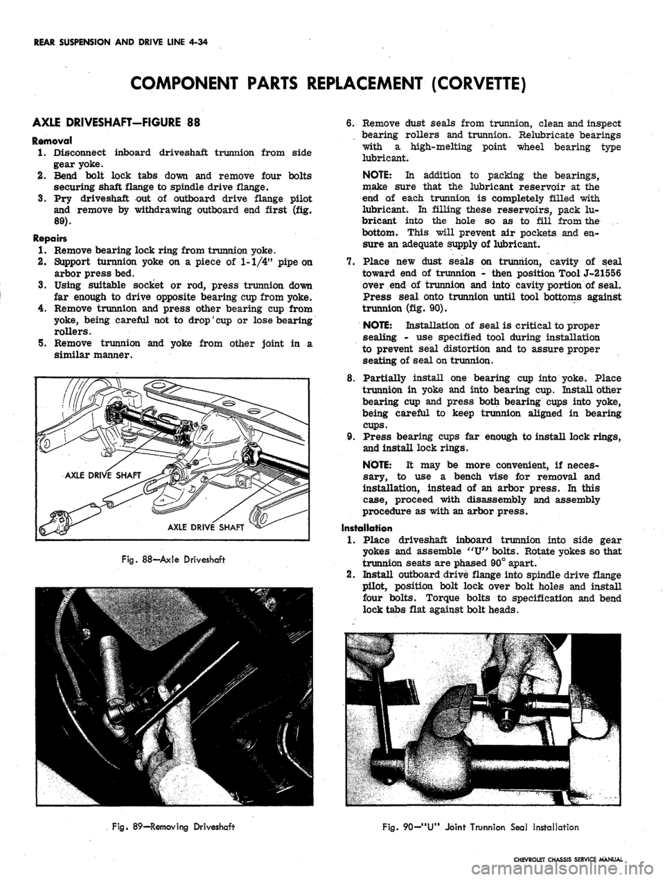
AXLE DRIVESHAFT-FIGURE 88
Removal
1.
Disconnect inboard driveshaft trunnion from side
gear yoke.
2.
Bend bolt lock tabs down and remove four bolts
securing shaft flange to spindle drive flange.
3.
Pry driveshaft out of outboard drive flange pilot
and remove by withdrawing outboard end first (fig.
89).
Repairs
1.
Remove bearing lock ring from trunnion yoke.
2.
Support turnnion yoke on a piece of 1-1/4" pipe on
arbor press bed.
3.
Using suitable socket or rod, press trunnion down
far enough to drive opposite bearing cup from yoke.
4.
Remove trunnion and press other bearing cup from
yoke, being careful not to
drop'
cup
or lose bearing
rollers.
5. Remove trunnion and yoke from other joint in a
similar manner.
3
AXLE
II 1
i
c
DRI\
c
y
'E SHAFT ^
AXLE
v
DRIVE^
SHAFT
•
Fig.
88—Axle Driveshaft
6. Remove dust seals from trunnion, clean and inspect
bearing rollers and trunnion. Relubricate bearings
with a high-melting point wheel bearing type
lubricant.
NOTE:
In addition to packing the bearings,
make sure that the lubricant reservoir at the
end of each trunnion is completely filled with
lubricant. In filling these reservoirs, pack lu-
bricant into the hole so as to fill from the .
bottom. This will prevent air pockets and en-
sure an adequate supply of lubricant.
7. Place new dust seals on trunnion, cavity of seal
toward end of trunnion - then position Tool J-21556
over end of trunnion and into cavity portion of seal.
Press seal onto trunnion until tool bottoms against
trunnion (fig. 90).
NOTE:
Installation of seal is critical to proper
sealing - use specified tool during installation
to prevent seal distortion and to assure proper
seating of seal on trunnion.
8. Partially install one bearing cup into yoke. Place
trunnion in yoke and into bearing cup. Install other
bearing cup and press both bearing cups into yoke,
being careful to keep trunnion aligned in bearing
cups.
9. Press bearing cups far enough to install lock rings,
and install lock rings.
NOTE:
It may be more convenient, if neces-
sary, to use a bench vise for removal and
installation, instead of an arbor press. In this
case, proceed with disassembly and assembly
procedure as with an arbor press.
Installation
1.
Place driveshaft inboard trunnion into side gear
yokes and assemble
"XJ"
bolts. Rotate yokes so that
trunnion seats are phased 90° apart.
2.
Install outboard drive flange into spindle drive flange
pilot, position bolt lock over bolt holes and install
four bolts. Torque bolts to specification and bend
lock tabs flat against bolt heads.
Fig. 89—Removing Driveshaft
Fig.
90—
"U"
Joint Trunnion Seal Installation
CHEVROLET CHASSIS SERVICE MANUAL
Page 226 of 659
REAR SUSPENSION AND DRIVE LINE 4-36
Fig.
94—Installing Pinion Oil Seal
DIFFERENTIAL CARRIER
Removal
1.
Disconnect spring end link bolts as outlined in
Spring—Removal, in this section.
2.
Disconnect axle drive shafts at carrier by removing
"U"
bolts securing trunnion to side gear yoke.
3.
Disconnect carrier front support bracket at frame
crossmember.
4.
Disconnect propeller shaft at transmission and at
companion flange. Slide transmission yoke forward
into transmission. Drop propeller shaft down and
Fig.
95-Pinion Sea! Installed
out toward the rear.
5. Mark camber cam and bolt relative location on strut
rod bracket and loosen cam bolts.
6. Remove four bolts securing bracket to carrier lower
surface and drop bracket. Remove camber cam bolts
and swing strut rods up and out of the way.
7. Remove eight carrier-to-cover bolts. Loosen bolts
gradually to allow lubricant to drain out.
8. With mounting bolts removed, pull carrier partially
out of cover, drop nose to clear crossmember and
gradually work carrier down and out.
Installation
1.
Clean inside of carrier cover and liberally grease
gasket surface. Place new gasket on cover.
2.
Cut heads off two l/2"-13 x 1-1/4" bolts and slot
unthreaded end. Install these aligning studs into two
below-center carrier bolt holes, one on each side.
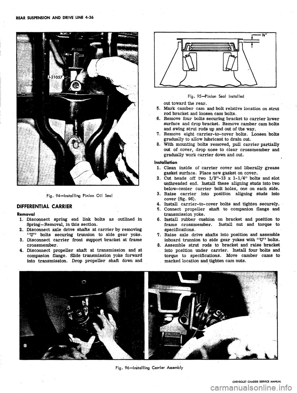
3.
Raise carrier into position aligning studs into
cover (fig. 96).
4.
Install carrier-to-cover bolts and tighten securely.
5. Connect propeller shaft to companion flange and
transmission yoke.
6. Install rubber cushion on bracket and position to
frame crossmember. Install hut and torque to
specifications.
7. Raise axle drive shafts into position and assemble
inboard trunnion to side gear yokes with "U" bolts.
8. Assemble strut rods to bracket and raise bracket
into position under carrier. Install four bolts and
torque to specifications. Move camber cams to
marked location and tighten cam nuts.
Fig.
96—Installing Carrier Assembly
CHEVROLET CHASSIS SERVICE MANUAL
Page 229 of 659
REAR SUSPENSION AND DRIVE LINE 4-39
Fig.
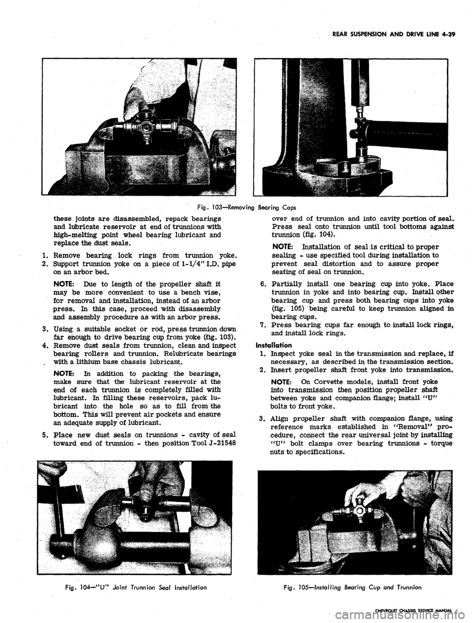
103—Removing Bearing Caps
these joints are disassembled, repack bearings
and lubricate reservoir at end of trunnions with
high-melting point wheel bearing lubricant and
replace the dust seals.
1.
Remove bearing lock rings from trunnion yoke.
2.
Support trunnion yoke on a piece of 1-1/4" I.D. pipe
on an arbor bed.
NOTE:
Due to length of the propeller shaft it
may be more convenient to use a bench vise,
for removal and installation, instead of an arbor
press.
In this case, proceed with disassembly
and assembly procedure as with an arbor press.
3.
Using a suitable socket or rod, press trunnion down
far enough to drive bearing cup from yoke (fig. 103).
4.
Remove dust seals from trunnion, clean and inspect
bearing rollers and trunnion. Relubricate bearings
with a lithium base chassis lubricant.
NOTE:
In addition to packing the bearings,
make sure that the lubricant reservoir at the
end of each trunnion is completely filled with
lubricant. In filling these reservoirs, pack lu-
bricant into the hole so as to fill from the
bottom. This will prevent air pockets and ensure
an adequate supply of lubricant.
5. Place new dust seals on trunnions - cavity of seal
toward end of trunnion - then position Tool J-21548
over end of trunnion and into cavity portion of seal.
Press seal onto trunnion until tool bottoms against
trunnion (fig. 104). .
NOTE:
Installation of seal is critical to proper
sealing - use specified tool during installation to
prevent seal distortion and to assure proper
seating of seal on trunnion.
6. Partially install one bearing cup into yoke. Place
trunnion in yoke and into bearing cup. Install other
bearing cup and press both bearing cups into yoke
(fig. 105) being careful to keep trunnion aligned in
bearing cups.
7. Press bearing cups far enough to install lock rings,
and install lock rings.
Installation
1.
Inspect yoke seal in the transmission and replace, if
necessary, as described in the transmission section.
2.
Insert propeller shaft front yoke into transmission.
NOTE:
On Corvette models, install front yoke
into transmission then position propeller shaft
between yoke and companion flange; install "U"
bolts to front yoke.
3.
Align propeller shaft with companion flange, using
reference marks established in "Removal" pro-
cedure, connect the rear universal joint by installing
"U"
bolt clamps over bearing trunnions - torque
nuts to specifications.
Fig.
104—"U" Joint Trunnion Seal installation
Fig.
105—Installing Bearing Cup and Trunnion
CHEVROLET CHASSIS SERVICE MANUAL
Page 231 of 659
REAR SUSPENSION AND DRIVE LINE 4-41
Fig.
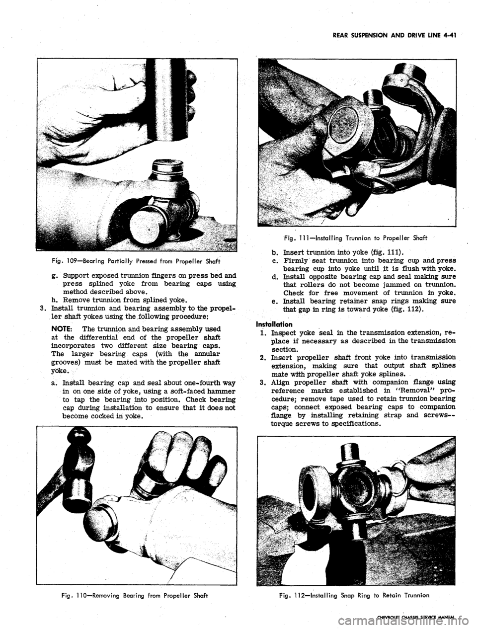
109—Bearing Partially Pressed from Propeller Shaft
g. Support exposed trunnion fingers on press bed and
press splined yoke from bearing caps using
method described above,
h. Remove trunnion from splined yoke.
3.
Install trunnion and bearing assembly to the propel-
ler shaft yokes using the,following procedure:
NOTE:
The trunnion and bearing assembly used
at the differential end of the propeller shaft
incorporates two different size bearing caps.
The larger bearing caps (with the annular
grooves) must be mated with the propeller shaft
yoke.
a. Install bearing cap and seal about one-fourth way
in on one side of yoke, using a soft-faced hammer
to tap the bearing into position. Check bearing
cap during installation to ensure that it does not
become cocked in yoke.
Fig.
Ill—Installing Trunnion to Propeller Shaft
b.
Insert trunnion into yoke (fig. 111).
c. Firmly seat trunnion into bearing cup and press
bearing cup into yoke until it is flush with yoke.
d. Install opposite bearing cap and seal making sure
that rollers do not become jammed on trunnion.
Check for free movement of trunnion in yoke.
e. Install bearing retainer snap rings making sure
that gap in ring is toward yoke (fig. 112).
Installation
1.
Inspect yoke seal in the transmission extension, re-
place if necessary as described in the transmission
section.
2.
Insert propeller shaft front yoke into transmission
extension, making sure that output shaft splines
mate with propeller shaft yoke splines.
3.
Align propeller shaft with companion flange using
reference marks established in "Removal" pro-
cedure; remove tape used to retain trunnion bearing
caps;
connect exposed bearing caps to companion
flange by installing retaining strap and screws—
torque screws to specifications.
Fig.
110—Removing Bearing from Propeller Shaft
Fig.
112—Installing Snap Ring to Retain Trunnion
CHEVROLET CHASSIS SERVICE MANUAL
Page 239 of 659
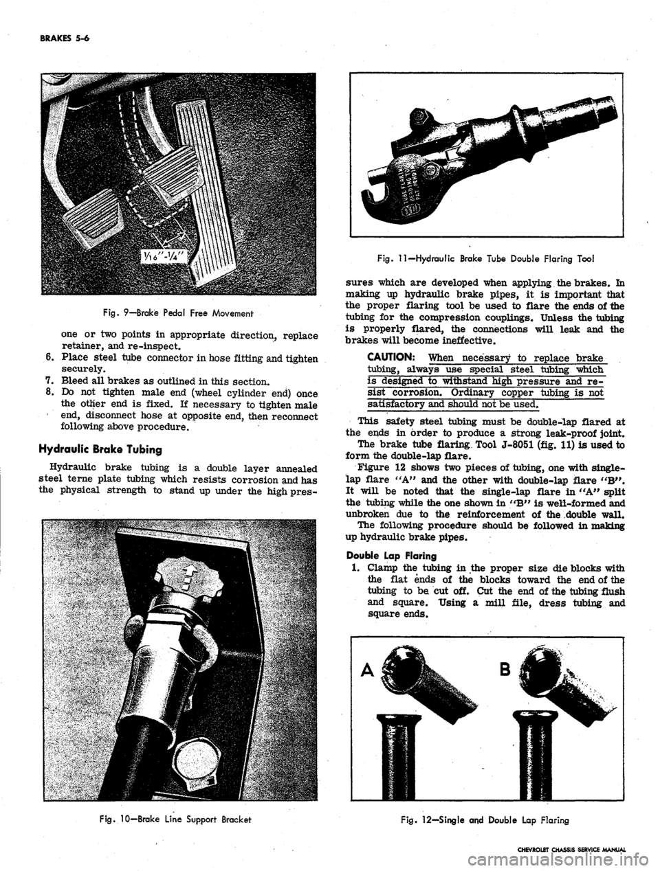
BRAKES 5-6
Fig.
9—Brake Pedal Free Movement
one or two points in appropriate direction, replace
retainer, and re-inspect.
6. Place steel tube connector in hose fitting and tighten
securely.
7. Bleed all brakes as outlined in this section.
8. Do not tighten male end (wheel cylinder end) once
the other end is fixed. If necessary to tighten male
1 end, disconnect hose at opposite end, then reconnect
following above procedure.
Hydraulic Brake Tubing
Hydraulic brake tubing is a double layer annealed
steel terne plate tubing which resists corrosion and has
the physical strength to stand up under the high pr.es-
Fig.
11—Hydraulic Brake Tube Double Flaring Tool
sures which are developed when applying the brakes. In
making up hydraulic brake pipes, it is important that
the proper flaring tool be used to flare the ends of the
tubing for the compression couplings. Unless the tubing
is properly flared, the connections will leak and the
brakes will become ineffective.
CAUTION: When necessary to replace brake
tubing, always use special steel tubing which
is designed to withstand high pressure and re-
sist corrosion. Ordinary copper tubing is not
satisfactory and should not be used.
This safety steel tubing must be double-lap flared at
the ends in order to produce a strong leak-proof joint.
The brake tube flaring. Tool J-8051 (fig. 11) is used to
form the double-lap flare.
Figure 12 shows two pieces of tubing, one with single-
lap flare "A" and the other with double-lap flare "B".
It will be noted that the single-lap flare in "A" split
the tubing while the one shown in "B" is well-formed and
unbroken due to the reinforcement of the double wall.
The following procedure should be followed in making
up hydraulic brake pipes.
Double Lap Flaring
1.
Clamp the tubing in the proper size die blocks with
the flat ends of the blocks toward the end of the
tubing to be cut off. Cut the end of the tubing flush
and square. Using a mill file, dress tubing and
square ends.
Fig.
10-Brake Line Support Bracket
Fig.
12—Single and Double Lap Flaring
CHEVROLET CHASSIS SERVICE MANUAL
Page 240 of 659
BRAKES 5-7
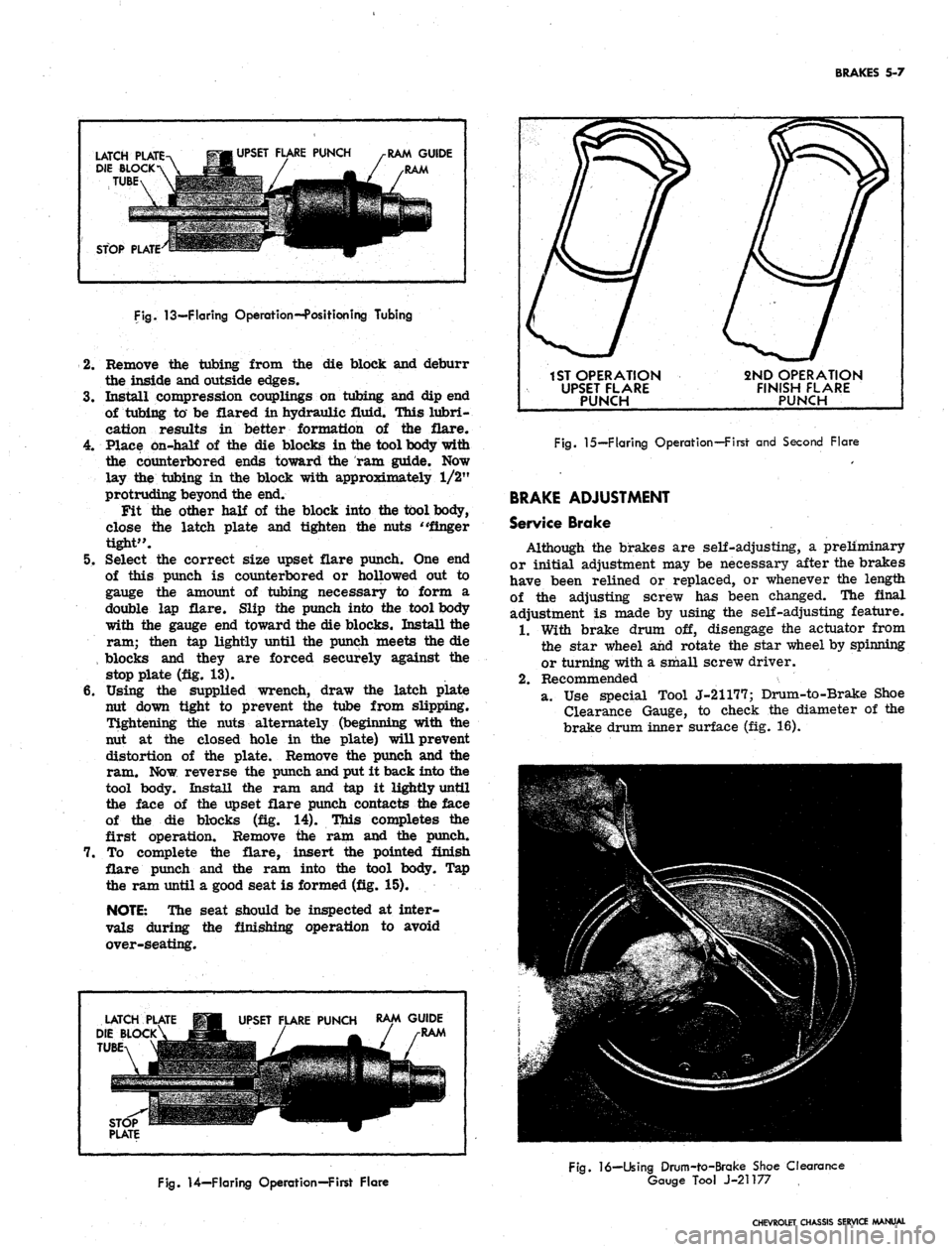
LATCH PLATE
DIE BLOCK
TUBE
UPSET FLARE PUNCH
RAM GUIDE
STOP PLATE
Fig.
13—Flaring Operation--Position ing Tubing
2.
Remove the tubing from the die block and deburr
the inside and outside edges.
3.
Install compression couplings on tubing and dip end
of tubing to be flared in hydraulic fluid. This lubri-
cation results in better formation of the flare.
4.
Place on-half of the die blocks in the tool body with
the counterbored ends toward the ram guide. Now
lay the tubing in the block with approximately 1/2"
protruding beyond the end.
Fit the other half of the block into the tool body,
close the latch plate and tighten the nuts "finger
tight".
5. Select the correct size upset flare punch. One end
of this punch is counterbored or hollowed out to
gauge the amount of tubing necessary to form a
double lap flare. Slip the punch into the tool body
with the gauge end toward the die blocks. Install the
ram; then tap lightly until the punch meets the die
, blocks and they are forced securely against the
stop plate (fig. 13).
6. Using the supplied wrench, draw the latch plate
nut down tight to prevent the tube from slipping.
Tightening the nuts alternately (beginning with the
nut at the closed hole in the plate) will prevent
distortion of the plate. Remove the punch and the
ram. Now reverse the punch and put it back into the
tool body. Install the ram and tap it lightly until
the face of the upset flare punch contacts the face
of the die blocks (fig. 14). This completes the
first operation. Remove the ram and the punch.
7. To complete the flare, insert the pointed finish
flare punch and the ram into the tool body. Tap
the ram until a good seat is formed (fig. 15).
NOTE:
The seat should be inspected at inter-
vals during the finishing operation to avoid
over-seating.
LATCH
DIE BLOCK
TUBE
UPSET FLARE PUNCH
RAM GUIDE
RAM
1ST OPERATION
UPSET FLARE
PUNCH
2ND OPERATION
FINISH FLARE
PUNCH
Fig.
15—Flaring Operation—First and Second Flare
BRAKE ADJUSTMENT
Service Brake
Although the brakes are self-adjusting, a preliminary
or initial adjustment may be necessary after the brakes
have been relined or replaced, or whenever the length
of the adjusting screw has been changed. The final
adjustment is made by using the self-adjusting feature.
1.
With brake drum off, disengage the actuator from
the star wheel and rotate the star wheel by spinning
or turning with a small screw driver.
2.
Recommended
a. Use special Tool J-21177; Drum-to-Brake Shoe
Clearance Gauge, to check the diameter of the
brake drum inner surface (fig. 16).
Fig.
14—Flaring Operation—First Flare
Fig.
16—Using Drum-to-Brake Shoe Clearance
Gauge Tool J-21177
CHEVROLET CHASSIS SERVICE MANUAL