turn CHEVROLET CAMARO 1967 1.G Chassis Workshop Manual
[x] Cancel search | Manufacturer: CHEVROLET, Model Year: 1967, Model line: CAMARO, Model: CHEVROLET CAMARO 1967 1.GPages: 659, PDF Size: 114.24 MB
Page 9 of 659
GENERAL INFORMATION 0-7
a vise using leather or wood on each side to prevent
damage to the cylinder,
7. Stake the retainer securely in place by staking the
cylinder metal over both edges of the retainer ends
using a suitable staking tool at right angles to the
top of the retainer and from the cast metal of the
cylinder over the retainer at each corner.
PUSHING, TOWING AND LIFTING
Pushing
NOTE:
Towing car to start is not recommended
due to the possibility of the disabled car ac-
celerating into tow car.
AUTOMATIC TRANSMISSION
Do not attempt to start the engine by pushing the car.
Should the battery become discharged, it will be neces-
sary to use an auxiliary battery with jumper cables to
start the engine.
CAUTION: To prevent damage to electrical
system, never connect booster batteries in ex-
cess of 12 volts and connect positive to positive
and negative to negative.
Manual Transmission
When a push start is necessary turn off all electrical
loads such as heater, radio, and if possible, lights, turn
on the key, depress the clutch, and place the shift lever
in high gear. Release the clutch when your speed reaches
10 to 15 miles per hour.
TOWING
The car may be towed safely on its rear wheels with
the (selector lever in "N" (Neutral) position at speeds
of 35 miles per hour or less under most conditions.
However, the drive shaft must be disconnected or the
car towed on its front wheels if 1) Tow speeds in excess
of 35 MPH are necessary, 2) Car must be towed for ex-
tended distances (over 50 miles) or, 3) Transmission is
not operating properly. If car is towed on its front
wheels, the steering wheel should be secured to maintain
a straight ahead position.
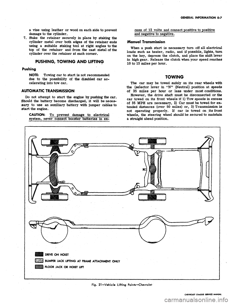
DRIVE ON HOIST
BUMPER JACK LIFTING AT FRAME ATTACHMENT ONLY
FLOOR JACK OR HOIST LIFT
Fig.
21-Vehicle Lifting Pointe-Chevroiet
CHEVROLET CHASSIS SERVICE MANUAL
Page 16 of 659
LUBRICATION 0-14
SAE 5W-30 oils may be used during periods when
temperatures of 32° and below are to be expected.
Types of Oils
In service, crankcase oils may form sludge and varnish
and under some conditions, corrosive acids unless pro-
tected against oxidation.
To minimize the formation of these harmful products
and to assure the use of oil best suited for present day
operating conditions, automobile manufacturers have de-
veloped a series of sequence tests designed to evaluate
the ability of any oil to properly lubricate automobile
engines.
It is recommended that only those oils which are
certified by their suppliers as meeting or exceeding the
maximum severity requirements of these sequence tests
(or GM Standard 4745-M) be used in Chevrolet engines.
Certified sequence tested oils will be described as such
on their containers.
Maintaining Oil Level
The oil gauge rod is marked "Full" and "Add Oil."
These notations have broad arrows pointing to the level
lines.
The oil level should be maintained between the
two lines, neither going above the "Full" line nor under
the "Add Oil" line. DO NOT OVERFILL. After operating
vehicle allow a few minutes for oil to return to crankcase
before checking oil level.
Check the oil level frequently and add oil when
necessary.
Oil and Filter Change Intervals
NOTE:
Under prolonged dusty driving condi-
tions,
it is recommended that these operations
be performed more often.
OIL
To insure continuation of best performance, low main-
tenance cost and long engine life, it is necessary to
change the crankcase oil whenever it becomes contami-
nated with harmful foreign materials. Under normal
driving conditions draining the crankcase and refilling
with fresh oil every 60 days or every 6000 miles which-
ever occurs first, is recommended.
It is always advisable to drain the crankcase only after
the engine has become thoroughly warmed up or reached
normal operating temperature. The benefit of draining is,
to a large extent, lost if the crankcase is drained when
the engine is cold, as some of the suspended foreign
material will cling to the sides of the oil pan and will not
drain out readily with the cold, slower moving oil.
OIL FILTER
Change engine oil filter every 6000 miles or every 6
months, whichever occurs first.
NOTE:
For Vehicles in heavy duty operation
involving continuous start-stop or prolonged idl-
ing, engine oil should be changed after 2500-
3000 miles of operation. The filter should be
changed after 5000-6000 miles of operation.
Crankcase Dilution
Probably the most serious phase of engine oil deterio-
ration is that of crankcase dilution which is the thinning
of the oil by fuel vapor leaking by pistons and rings and
mixing with the oil and by condensation of water on the
cylinder walls and crankcase.
Leakage of fuel, or fuel vapors, into the oil pan occurs
mostly during the "warming up" period when the fuel is
not thoroughly vaporized and burned. Water vapor enters
the crankcase through normal engine ventilation and
through exhaust gas blow-by. When the engine is not
completely warmed up, these vapors condense, combine
with the condensed fuel and exhaust gases and form acid
compounds in the crankcase.
As long as the gases and internal walls of the crank-
case are hot enough to keep water vapor from con-
densing, no harm will result. However, when the engine
is run in low temperatures moisture will collect and
unite with the gases formed by combustion resulting in
an acid formation. The acid thus formed is likely to
cause serious etching or pitting which will manifest itself
in excessively rapid wear on piston pins, camshaft
bearings and other moving parts of the engine, oftentimes
causing the owner to blame the car manufacturer or the
lubricating oil when in reality the trouble may be traced
back to the character of fuel used, or a condition of the
engine such as excessive blowby or improper carburetor
adjustment.
Automatic Control Devices to Minimize
Crankcase Dilution
All engines are equipped with automatic devices which
aid greatly in minimizing the danger of crankcase
dUution.
The thermostat, mounted in the cylinder head water
outlet, restricts the flow of water to the radiator until a
predetermined temperature is reached, thus minimizing
the length of time required to reach efficient operating
temperature, reducing the time that engine temperatures
are conducive to vapor condensation.
A water by-pass is included in the cooling system,
utilizing a hole in the front of, the cylinder block. This
allows a limited circulation of coolant, bypassing the
thermostat until thermostat opening temperatures are
reached. This system provides a uniform coolant tem-
perature throughout the engine, eliminating localized
hot-spots, improving exhaust valve life, provides fast
warmrup of lubricating oil and fast temperature rise in
the coolant which provides fast heater operation in cold
weather.
A thermostatic heat control on the exhaust manifold
during the warming up period, automatically directs the
hot exhaust gases against the center of the intake mani-
fold, greatly aids in proper vaporization of the fuel.
An automatic choke reduces the danger of raw or
unvaporized fuel entering the combustion chamber and
leaking into the oil reservoir.
An.
efficient crankcase ventilating system drives off
fuel vapors and aids in the evaporation of the raw fuel
and water which may find its way into the oil pan.
CRANKCASE BREATHER CAP
Clean and re-oil at every oil change..
CHEVROLET CHASSIS SERVICE MANUAL
Page 17 of 659
LUBRICATION 0-15
CRANKCASE VENTILATION VALVE
VALVE TYPE
NOTE: Under prolonged dusty driving condi-
tions,
it is recommended that these operations
be performed more often. Every 12,000 miles
or 12 months the valve should be replaced.
Connecting hoses, fittings, flame arrestor and
crankcase breather cap (where used) should be
cleaned. At every oil change the system should
be tested for proper function and serviced, if
necessary.
FUEL FILTER
Replace filter element located in carburetor inlet if
flooding occurs, if engine surges during constant speed
operation (pulsating effect) or if poor performance is
experienced during acceleration or at higher speeds.
AIR CLEANER
NOTE: Under prolonged dusty driving condi-
tions,
it is recommended that these operations
be performed more often.
POLYURETHANE TYPE-
Every 12,000 miles clean element in solvent, squeeze
out solvent, then soak in engine oil and squeeze out
excess.
OIL WETTED PAPER ELEMENT TYPE-
First 12,000 miles inspect or test element; if satis-
factory, re-use element but recheck every 6,000 miles
until replaced. Element must not be washed, oiled,
tapped or cleaned with an air hose.
BATTERY TERMINAL WASHERS
Battery terminals have felt washers between top of
case and cable connections to minimize corrosive action
of battery acid. These felt washers should be saturated
with engine oil every 6,000 miles.
DISTRIBUTOR
4 and 6-Cylinder Engine—Remove distributor cap and
rotate lubricator 1/2 turn at 12,000 mile intervals. Re-
place at 24,000 mile intervals.
8-Cylinder Engine—Change cam lubricator end for end
at 12,000 mile intervals. Replace at 24,000 mile
intervals.
REAR AXLE AND 3-SPEED AND
OVERDRIVE, 4-SPEED TRANSMISSIONS
The passenger car operates under the most severe
lubrication conditions at high speed and requires a hypoid
lubricant which will meet this condition.
Recommended Lubricants
Standard Rear Axles—SAE 90 "Multi-Purpose" gear
lubricant.
Positraction Rear Axles—Use special Positraction
lubricant.
CAUTION: Straight Mineral Oil gear lubricants
must not be used in hypoid rear axles.
Transmissions—SAE 90 "Multi-Purpose" gear
lubricant.
The SAE 90 viscosity grade is recommended for year
round use. However, when extremely low temperatures
are encountered for protracted periods during the winter
months, the SAE 80 viscosity grade may be used.
"Multi-Purpose" Gear Lubricants
Gear lubricants that will satisfactorily lubricate hypoid
rear axles have been developed and are commonly re-
ferred to as ' 'Multi-Purpose" gear lubricants meeting
U.S.
Army Ord. Spec. MIL-L-2105B.
These lubricants can also be satisfactorily used in
manual transmissions.
CAUTION: With Positraction rear axles use
special Positraction lubricant.
"Multi-Purpose" gear lubricants must be manufac-
tured under carefully controlled conditions and the
lubricant manufacturer must be responsible for the
satisfactory performance of his product. His reputation
is the best indication of quality.
Lubricant Additions
The lubricant level in the axle and transmission hous-
ings should be checked periodically. (Every 6,000 miles.)
It is recommended that any additions required to bring
up the lubricant level be made using the same type lubri-
cant already in the housing.
When checking lubricant level in transmission or rear
axle the unit being cheeked should be at operating
temperature. With unit at operating temperature the
lubricant should be level with bottom of the filler plug
hole.
If the lubricant level is checked with the unit cold
the lubricant level should be 1/2 inch below the filler
plug hole.
Lubricant Changes
The rear axle lubricant does not require changing for
the life of the vehicle. If additions are needed, or when
refilling the axle after service procedures, use lubricants
described above.
POWERGLIDE TRANSMISSION
NOTE: Every 12,000 miles, it is recommended
that the Powerglide low band be adjusted as
specified in Section 7 of this manual.
Every 6,000 miles--Check fluid level on dipstick with
engine idling, selector lever in neutral position, parking
brake set and transmission at operating temperature. If
fluid level is below full mark on dip stick, adding a small
amount of Automatic Transmission Fluid, General Motors
Automatic Transmission Fluid (Part Numbers 1050568-
69,
70) is recommended. If this fluid is not obtainable,
use Automatic Transmission Fluid Type 'A' bearing the
mark AQ-ATF followed by a number and the suffix letter
'A'.
Recheck fluid level on dip stick and again add a
small amount of fluid if needed to bring level to full
mark. DO NOT OVERFILL.
CHEVROLET CHASSIS SERVICE MANUAL
Page 18 of 659
LUBRICATION 0-16
Every 12,000 miles (more frequently*, depending on
severity of service, if vehicle is used to pull trailers,
carry full loads during high ambient temperatures,
operate in mountainous terrain or operate under other
severe conditions--Remove fluid from the transmission
sump and add one and a half quarts of fresh fluid for
Camaro and Chevy II and two quarts for Chevrolet,
Chevelle, and Corvette. Operate transmission through all
ranges and check fluid level as described above.
•Except if vehicle is equipped with transmission pro-
vided in heavy duty service options. If so equipped,
drain converter and pump every 12,000 miles and add
approximately seven and a half quarts of fresh fluid
for Chevy II and nine quarts for Chevrolet and Chevelle.
TURBO HYDRA-MATIC
Lubrication. recommendations for the Turbo Hydra-
Matic are the same as outlined for the Powerglide
transmission except for fluid capacity and filter change
listed below.
After checking transmission fluid level it is important
that the dip stick be pushed all the way into the fill tube.
Every 12,000 miles — after removing fluid from the
transmission sump, approximately 7 1/2 pints of fresh
fluid will be required to return level to proper mark on
the dip stick.
Every 24,000 miles, or at every other fluid change--
the transmission sump strainer should be replaced.
FRONT WHEEL BEARINGS
It is necessary to remove the wheel and hub assembly
to lubricate the bearings. The bearing assemblies should
be cleaned before repacking with lubricant. Do not pack
the hub between the inner and outer bearing assemblies
or the hub caps, as this excessive lubrication results in
the lubricant working out into the brake drums and
linings.
Front wheels of all passenger car models are equipped
with tapered roller bearings and should be packed with a
high melting point water resistant front wheel bearing
lubricant whenever wheel and hub are removed.
CAUTION: "Long fibre" or "viscous" type
lubricant should not be used. Do not mix wheel
bearing lubricants. Be sure to thoroughly clean
bearings and hubs of all old lubricant before
repacking.
The proper adjustment of front wheel bearings is one
of the important service operations- that has a definite
bearing on safety. A car with improperly adjusted front
wheel bearings lacks steering stability, has a tendency to
wander or shimmy and may have increased tire wear.
The adjustment of these bearings is very critical. The
procedure is covered in Section 3 of this manual under
Front Wheel Bearings—Adjust,
MANUAL STEERING GEAR
Check lubricant level every 36,000 miles. If required,
add EP Chassis Lubricant.
POWER STEERING
On models equipped with power steering gear, check
fluid at operating temperature in pump reservoir. Add
GM Power Steering Fluid, or, if this is not available, use
Automatic Transmission Fluid "Type A" bearing the
mark AQ-ATF followed by a number and the suffix letter
'A'
to bring level to full mark on dip stick.
AIR CONDITIONING
After the first 6,000 miles, check all hose clamp
connections for proper tightness.
Every 6,000 miles check sight glass under the hood,
after the system has been in operation for several
minutes. Sight glass should be clear but may, during
milder weather, show traces of bubbles. Foam or dirt
indicate a leak which should be repaired immediately.
BRAKE MASTER CYLINDER
Check level every 6,000 miles and maintain 1/4" below
lowest edge of each filler opening with GM Hydraulic
Brake Fluid Supreme No. 11.
PARKING BRAKE
Every 6,000 miles, apply water resistant lube to park-
ing brake cable, cable guides and at all operating links
and levers.
CLUTCH CROSS-SHAFT
Periodic lubrication of the clutch cross shaft is not
required. At 36,000 miles or sooner, if necessary;
remove plug, install lube fitting and apply CHASSIS
LUBRICANT.
CHASSIS LUBRICATION
For chassis lubrication, consult the lubrication chart.
It shows the points to be lubricated and how often the
lubricant should be applied.
The term "chassis lubricant" as used in this manual,
describes a water resistant EP chassis grease designed
for application by commercial pressure gun equipment.
CHEVROLET CHASSIS SERVICE MANUAL
Page 26 of 659
HEATER AND AIR CONDITIONING 1A-3
linkage of this lever which will provide partial airflow
only to the defroster duct and which should be used for,
all normal defogging operations.
CORVETTE
Heater components are attached to the dash panel on
the right side of the vehicle with the air inlet assembly
on the engine side and the heater and air distributor
assemblies beneath the instrument panel within the pas-
senger compartment.
The heater operates on outside air only with the blower
receiving its air flow from the cowl vent plenum
chamber.
No water valve is utilized in the system. Therefore,
water flows through the heater core constantly while
the engine is running, keeping the core at maximum
temperature at all times.
Airflow through the system is shown in Figure 1.
Controls
Two knobs control all heater operations:
The FAN-TEMP knob is rotated to turn the blower
on and off and control blower speed and is pulled out
as desired to regulate heater temperature.
The AIR-DEF knob is the air on-and-off control as
well as the defroster control.
Temperature Damper: Door
At the heart of the heater operation is the temperature
damper door. Air from the blower follows parallel paths
through the distributor duct, with one path passing
through the heater core and the other path bypassing the
core.
The temperature damper door is placed in the duct
so that, when closed, the path of the heated air leaving
the heater core is blocked while the ambient air path
remains open. Positive closing of this door when no
heat is being called for is assured by a cam assembly
at the door operating lever. As the FAN-TEMP knob
is pulled out, the damper door is opened accordingly,
allowing varying proportions of heated air to mix with
the unheated airflow, thus providing heater outlet tem-
perature control. With the knob pulled fully out the
Fig.
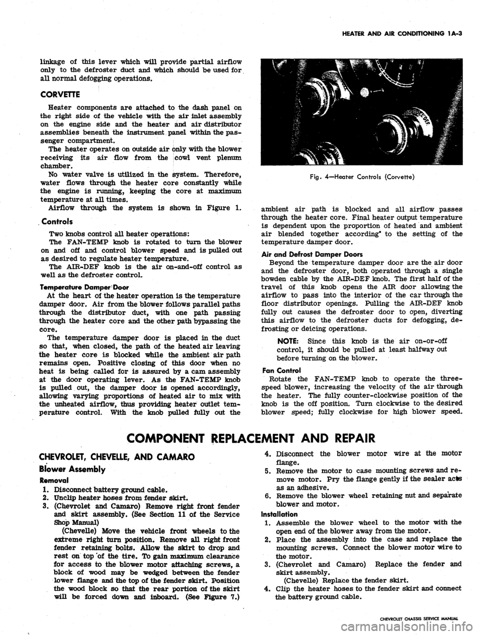
4—Heater Controls (Corvette)
ambient air path is blocked and all airflow passes
through the heater core. Final heater output temperature
is dependent upon the proportion of heated and ambient
air blended together according* to the setting of the
temperature damper door.
Air and Defrost Damper Doors
Beyond the temperature damper door are the air door
and the defroster door, both operated through a single
bowden cable by the AIR-DEF knob. The first half of the
travel of this knob opens the AIR door allowing the
airflow to pass into the interior of the car through the
floor distributor openings. Pulling the AIR-DEF knob
fully out causes the defroster door to open, diverting
this airflow to the defroster ducts for defogging, de-
frosting or deicing operations.
NOTE: Since this knob is the air on-or-off
control, it should be pulled at least halfway out
before turning on the blower.
Fan Control
Rotate the FAN-TEMP knob to operate the three-
speed blower, increasing the velocity of the air through
the heater. The fully counter-clockwise position of the
knob is the off position. Turn clockwise to the desired
blower speed; fully clockwise for high blower speed.
COMPONENT REPLACEMENT AND REPAIR
CHEVROLET, CHEVELLE, AND CAMARO
Blower Assembly
Removal
1.
Disconnect battery ground cable.
2.
Unclip heater hoses from fender skirt.
3.
(Chevrolet and Camaro) Remove right front fender
and skirt assembly. (See Section 11 of the Service
Shop Manual)
(Chevelle) Move the vehicle front wheels to the
extreme right turn position. Remove all right front
fender retaining bolts. Allow the skirt to drop and
rest on top of the tire. To gain maximum clearance
for access to the blower motor attaching screws, a
block of wood may be wedged between the fender
lower flange and the top of the fender skirt. Position
the wood block so that the rear portion of the skirt
will be forced down and inboard. (See Figure 7.)
4.
Disconnect the blower motor wire at the motor
flange.
5.
Remove the motor to case mounting screws and re-
move motor. Pry the flange gently if the sealer acts
as an adhesive.
6. Remove the blower wheel retaining nut and separate
blower and motor.
Installation
1.
Assemble the blower wheel to the motor with the
open end of the blower away from the motor.
2.
Place the assembly into the case and replace the
mounting screws. Connect the blower motor wire to
the motor.
3.
(Chevrolet and Camaro) Replace the fender and
skirt assembly.
(Chevelle) Replace the fender skirt.
4.
Clip the heater hoses to the fender skirt and connect
the battery ground cable.
CHEVROLET CHASSIS SERVICE MANUAL
Page 41 of 659
HEATER AND AIR CONDITIONING 1A-18
HIGH BLOWER
i DELAY RELAY
AMBIENT-SUN
SENSOR AND
COMPRESSOR SWITCH
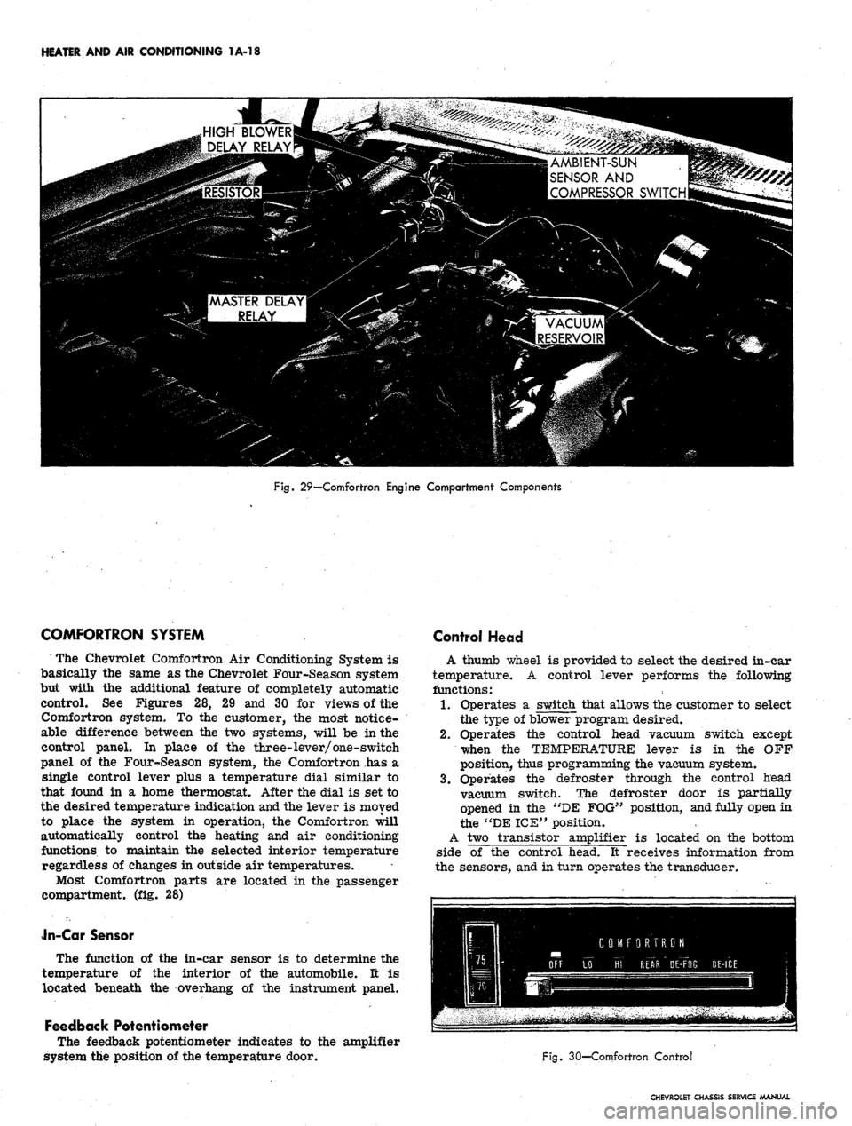
Fig. 29—Comfortron Engine Compartment Components
COMFORTRON SYSTEM
The Chevrolet Comfortron Air Conditioning System is
basically the same as the Chevrolet Four-Season system
but with the additional feature of completely automatic
control. See Figures 28, 29 and 30 for views of the
Comfortron system. To the customer, the most notice-
able difference between the two systems, will be in the
control panel. In place of the three-lever/one-switch
panel of the Four-Season system, the Comfortron has a
single control lever plus a temperature dial similar to
that found in a home thermostat. After the dial is set to
the desired temperature indication and the lever is moved
to place the system in operation, the Comfortron will
automatically control the heating and air conditioning
functions to maintain the selected interior temperature
regardless of changes in outside air temperatures.
Most Comfortron parts are located in the passenger
compartment, (fig. 28)
Jn-Car Sensor
The function of the in-car sensor is to determine the
temperature of the interior of the automobile. It is
located beneath the overhang of the instrument panel.
Feedback Potentiometer
The feedback potentiometer indicates to the amplifier
system the position of the temperature door.
Control Head
A thumb wheel is provided to select the desired in-car
temperature. A control lever performs the following
functions:
1.
Operates a switch that allows the customer to select
the type of blower program desired.
2.
Operates the control head vacuum switch except
when the TEMPERATURE lever is in the OFF
position, thus programming the vacuum system.
3.
Operates the defroster through the control head
vacuum switch. The defroster door is partially
opened in the "DE FOG" position, and fully open in
the "DE ICE" position.
A two transistor amplifier is located on the bottom
side of the control head. It receives information from
the sensors, and in turn operates the transducer.
Fig. 30—Comfortron Control
CHEVROLET CHASSIS SERVICE MANUAL
Page 43 of 659
HEATER AND AIR CONDITIONING 1A-20
and its resistance is decreasing. In the HI FRONT
position, two thermistors (the master delay and high
blower delay thermistors) are warming. The air
door is in recirculation position until the engine
coolant reaches 75 degrees.
2.
The coolant reaches then 75 degrees and the thermal
vacuum valve opens applying vacuum to the air door
to admit outside air (unless the temperature dial is
set for cooling). Ram air will flow through the sys-
tem when the car is moving.
3.
Next, the master delay thermistor attains the tem-
perature at which it will pass sufficient current to
close the circuit through the master delay relay.
The relay circuit powers the blower motor at 9 volts.
4.
If the control is in the HI FRONT position, the high
blower delay thermistor will close the circuit
through the high blower relay which supplies full
available voltage to the blower motor. This function
occurs after the master delay thermistor has taken
effect because the high blower delay thermistor
uses the master delay type thermistor with a 10 ohm
1/4 watt resistor connected in
.
series. The nigh
blower delay thermistor must then warm to a higher
temperature than the master delay thermistor before
its resistance (plus that of the 10 ohm resistor)
drops enough to actuate the high blower relay.
5. If the controls are set for DE ICE, full outside air
and full voltage to the blower motor are effective
immediately regardless of temperatures or elapsed
times o
In accomplishing automatic control, the system follows
three steps to transform an electronic signal into me-
chanical energy through which the control is achieved.
Electronic Circuit
Two temperature sensors (Thermistors), and the duct
potentiometer connected in series, are located so as to
sense the temperature of the outside air, inside air and
system output air. The resistance of each sensor will
vary according to its temperature. The control head
temperature dial varies in resistance as it is adjusted by
the operator to suit his comfort requirements. The
resistance of the temperature dial control is applied
directly to the amplifier and is not in series with the
sensors and duct potentiometer. Thus temperature dif-
ferences in the sensor string plus the requirements fed
into the system by the operator cause changes in total
circuit resistance which allow a varying voltage flow
through the circuit.
Changing the Electronic Signal to Electrical Voltage
This minute voltage flow from the sensor string -
temperature dial circuit - is fed into the amplifier where
it is transformed into a usable amplifier output voltage,
the strength of which is determined by the strength of the
original amplifier input signal. This voltage is then
supplied to the transducer.
Changing the Electrical Voltage to a Vacuum Signal
Amplifier output voltage, varying according to tem-
perature requirements, is converted by the Transducer
into a modulator transducer output vacuum. This modu-
lated vacuum is applied to the Power Servo.
Changing the Vacuum Signal to Mechanical Energy
The Power Servo, controlled by the modulated Trans-
ducer output vacuum, operates the vacuum electrical and
mechanical components of the system as required to
provide automatic control of system operation.
Other major system components are mounted con-
ventionally in the engine compartment. Underhood com-
ponents and system airflow remain much the same as in
the Four-Season system except for the addition of the
automatic control provisions. The system operates on
100%
outside air, a mixture of outside and inside air, or
100%
recirculated air depending on the demands of the
system. The diaphragm operated .air selector door will
modulate outside air to the system during maximum air
conditioning requirements when the control unit is in
"Hi Front" position. Control of the blower is also com-
pletely automatic and dependent upon system demands.
Controls
The Comfortron controls the Chevrolet air conditioner
and heater in such a precise manner that the automobile
temperature remains relatively constant under all driving
conditions. By adjusting the thumb wheel on the Control
Head to any temperature desired between 65° and 85° F.
(See Figure 27) the automatic system will adjust the in-
car temperature even though the outside weather condi-
tions may vary considerably. The system will provide
maximum capacity for heating or cooling until the in-car
temperature reaches the pre-set Control Head Tempera-
ture. Where cooling is required, the system will start
immediately upon being turned "ON". During marginal
ambient temperatures the system will not always start
at the highest blower speeds of the control setting.
Therefore, occasionally the system can't be heard
starting*
Five over-riding functions are available so that special
conditions can be handled. Each Control Head function
will be discussed in detail below:
"Off" Position
In the "Off" position, the blower is turned off and the
outside air door is closed. No outside air should enter
the automobile.
"Lo Front" Position
The blower has five low to moderate speeds; Hi, M3,
M2,
M1 and Lo. The blower voltage will shift as directed
by the automatic controls. The "Lo Front" position
provides a quieter mode of automatic operation due to
reduction of blower noise.
"Hi Front" Position
The "Hi Front" position provides five high blower
speeds as called for by the automatic controls: The use
of the "Hi" blower speed results in a rapid cool down in
hot weather and rapid heating during cold weather. As
the in-car temperature approaches the temperature set-
ting on the Comfortron Control Head, the blower speed
will change, provided mild outside temperatures are
experienced. During very hot or cold weather, the blower
will reduce its speed only to the point where it is still
capable of maintaining the correct inrcar temperature.
"Rear" Position
The "Rear" position provides five high blower speeds.
The automatic controls select these speeds and blend the
discharge air to the proper temperature. By the use of
high blower speeds, increased airflow is obtained for
better rear seat passenger comfort.
CHEVROLET CHASSIS SERVICE MANUAL
Page 44 of 659
HEATER AND AIR CONDITIONING 1A-21
"De-Fog"
Position
In the event that the front windshield should require
removal of a fogging condition, the owner at his option
may direct air to the windshield. The "De-Fog" position
directs part of the air to the windshield while retaining a
certain amount through the floor outlets. The temper-
ature of the air remains the same as it was prior to the
control being placed in the "De-Fog" position. Five
blower speeds are available. The temperature of the air
and the blower speed are selected by the automatic
controls and are dependent upon the in-car temperature.
"De-Ice" Position
The "De-Ice" position provides full heat with "Hi"
blower directing the entire airflow to the windshield to
melt ice. The automatic controls are completely defeated
and as a result, full heat with "Hi" blower are the only
conditions that can be received. The system will turn on
immediately in this position even though the engine
coolant might be cold.
General Information
Three start up conditions can be achieved with
Comfortron.
Weather
Cold
Method of Starting System
System starts as soon as engine coolant is
hot.
Hot System starts immediately when AC is
required.
Any System starts immediately in "De-Ice"
position.
UNIVERSAL SYSTEM
A self-contained unit, the dealer installed Universal
System operates on recirculated air only and entirely
independent of the vehicle heater. Recirculated inside air
is drawn into the unit, passed through the evaporator core
and into the car through the adjustable outlets in the
evaporator case. The entire unit mounts compactly
beneath the dash. Temperature control is by means of a
thermostatic switch.
The compressor used with the Universal System is
identical to that used for the Four-Season system except
for displacement. Underhood components are similar in
placement to the Four-Season system.
Controls
Universal system controls are the AIR knob controlling
the three speed blower motor switch and the TEMP knob
which controls the setting of the thermostatic switchi
Switch adjustment is covered elsewhere in this section.
When operating this system the Heater must be fully off.
CHEVY II ALL-WEATHER SYSTEM
The Chevy n All-Weather Air Conditioning System,
Figure 33, operates in conjunction with the heater to
provide a complete air conditioning system operating on
either outside air, recirculated air or a combination of
both. The cooling unit attaches to the heater distributor
and utilizes the heater blower. Several controls allow
full use of either the heating or cooling features of the
system. During marginal weather, it is possible to pro-
vide heated air at floor level and cooled air at breath
level.
A schematic view of the air conditioning underdash
components is provided in Figure 34 to aid in under-
standing airflow and control operation.
The evaporator assembly, located in the passenger
compartment attached directly to the heater distributor,
contains the evaporator core, expansion valve, thermo-
static switch and the air conditioning "ON" knob. The
thermostatic switch, utilized as the cooling control, feels
the temperature of the cooled air leaving the evaporator
core and turns the compressor on and off in accordance
with cooling needs. Refrigerant lines connect the evap-
orator assembly to the other system components located
in the engine compartment.
The six cylinder air conditioning compressor, com-
pletely field serviceable, is bracket-mounted to the
engine and is belt driven from the crankshaft pulley. A
muffler assembly, designed to eliminate compressor
pulsations is an integral part of the compressor con-
nector block. The condenser is mounted on the radiator
support just ahead of the engine radiator. The receiver-
dehydrator, with its sight glass, is located on the right
fender skirt.
Controls
Control of the air conditioning system is achieved
through the use of the heater control on the instrument
panel as well as the two knobs located on the air condi-
tioning unit itself (fig. 35).
Air Conditioning "ON" Knob
Labeled "Pull for Air Cond.", this knob diverts air-
flow from the floor distributor and through the air condi-
tioning unit. Initial movement of this knob also actuates a
switch, located at the damper door, which energizes the
compressor clutch thus putting the system into operation
and under the control of the thermostatic switch.
Temp-Cool Knob
This knob controls the thermostatic switch. Turn the
knob clockwise for more cooling, counter-clockwise for
less cooling.
Air Lever
This lever actuates the damper within the assembly
which chooses between recirculated air or outside air.
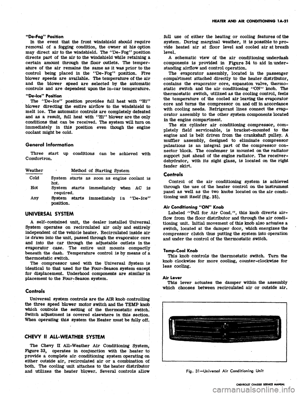
Fig.
31-Universal Air Conditioning Unit
CHEVROLET CHASSIS SERVICE MANUAL
Page 47 of 659
HEATER AND AIR. CONDITIONING 1A-24
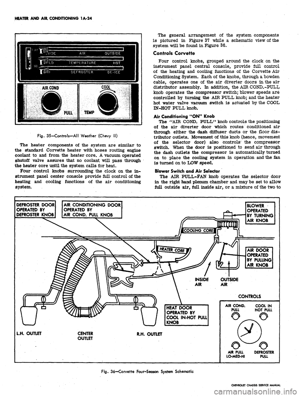
Fig. 35-Controls-AII Weather (Chevy II)
The heater components of the system are similar to
the standard Corvette heater with hoses routing engine
coolant to and from the heater core. A vacuum operated
shutoff valve assures that no coolant will pass through
the heater core until the system calls for heat.
Four control knobs surrounding the clock on the in-
strument panel center console provide full control of the
heating and cooling functions of the air conditioning
system.
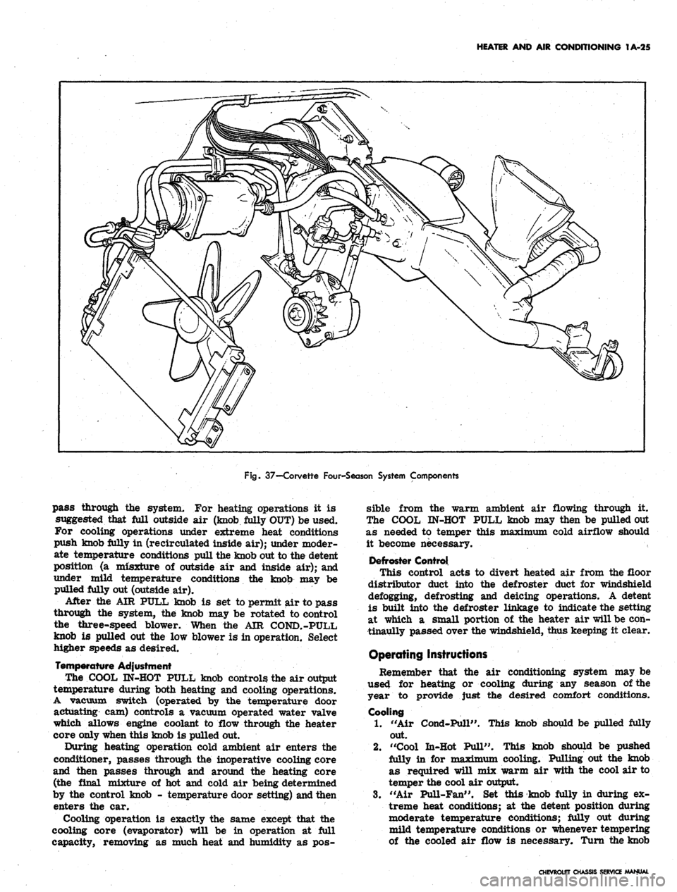
The general arrangement of the system components
is pictured in Figure 37 while a schematic view of the
system will be found in Figure 36.
Controls Corvette
Four control knobs, grouped around the clock on the
instrument panel central console, provide full control
of the heating and cooling functions of the Corvette Air
Conditioning System. Each of the knobs, through a bowden
cable, operates one of the air diverter doors in the air
distributor assembly. In addition, the AIR COND.-PULL
knob operates the compressor switch; blower speeds are
controlled by turning the AIR PULL knob; and the heater
hot water valve vacuum switch is actuated by the COOL
IN-HQT PULL knob.
Air Conditioning "ON" Knob
The "AIR COND. PULL" knob controls the positioning
of the air diverter door which routes conditioned air
through either the dash diffuser ducts or the floor dis-
tributor outlets. Movement of this knob (hence, movement
of the selector door) also controls' the compressor
switch. When the door is positioned to send air through
the dash outlets the compressor is automatically turned
on to place the cooling system in operation and the fan
is turned on to LOW speed.
Blower Switch and Air Selector
The AIR PULL-FAN knob operates the selector door
in the right hand plenum chamber and may be set to allow
full outside air, full inside air, or a mixture of the two to
DEFROSTER DOOR
OPERATED BY
DEFROSTER KNOB
AIR CONDITIONING DOOR
OPERATED BY
AIR COND. PULL KNOB
BLOWER
OPERATED
BY TURNING
AIR KNOB
AIR DOOR
OPERATED
BY PULLING
AIR KNOB
OUTSIDE
AIR
CONTROLS
HEAT DOOR
OPERATED BY
COOL IN-HOT PULL
KNOB
L.H. OUTLET
CENTER
OUTLET
R.H. OUTLET
AIR COND.
PULL
COOL IN
HOT PULL
AIR PULL
LO-MED-HI
DEFROSTER
PULL
Fig.
36—Corvette Four-Season System Schematic
CHEVROLET CHASSIS SERVICE MANUAL
Page 48 of 659
HEATER AND AIR CONDITIONING 1A-25
Fig.
37—-Corvette Four-Season System Components
pass through the system. For heating operations it is
suggested that Ml outside air (knob Mly OUT) be used.
For cooling operations under extreme heat conditions
push knob fully in (recirculated inside air); under moder-
ate temperature conditions pull the knob out to the detent
position (a misxture of outside air and inside air); and
under mild temperature conditions the knob may be
pulled fully out (outside air).
After the AIR PULL knob is set to permit air to pass
through the system, the knob may be rotated to control
the three-speed blower. When the AIR COND.-PULL
knob is pulled out the low blower is in operation. Select
higher speeds as desired.
Temperature Adjustment
The COOL IN-HOT PULL knob controls the air output
temperature during both heating and cooling operations.
A vacuum switch (operated by the temperature door
actuating cam) controls a vacuum operated water valve
which allows engine coolant to flow through the heater
core only when this knob is pulled out.
During heating operation cold ambient air enters the
conditioner, passes through the inoperative cooling core
and then passes through and around the heating core
(the final mixture of hot and cold air being determined
by the control knob - temperature door setting) and then
enters the car.
Cooling operation is exactly the same except that the
cooling core (evaporator) will be in operation at Ml
capacity, removing as much heat and humidity as pos-
sible from the warm ambient air flowing through it.
The COOL IN-HOT PULL knob may then be pulled out
as needed to temper this maximum cold airflow should
it become necessary.
Defroster Control
This control acts to divert heated air from the floor
distributor duct into the defroster duct for windshield
defogging, defrosting and deicing operations. A detent
is built into the defroster linkage to indicate the setting
at which a small portion of the heater air will be con-
tinaully passed over the windshield, thus keeping it clear.
Operating Instructions
Remember that the air conditioning system may be
used for heating or cooling during any season of the
year to provide just the desired comfort conditions.
Cooling
1.
"Air Cond-Pull". This knob should be pulled fully
out.
2.
"Cool In-Hot Pull". This knob should be pushed
fully in for maTriTr»"Tn cooling. Pulling out the knob
as required will mix warm air with the cool air to
temper the cool air output.
3.
"Air Pull-Fan". Set this knob fully in during ex-
treme heat conditions; at the detent position during
moderate temperature conditions; fully out during
mild temperature conditions or whenever tempering
of the cooled air flow is necessary. Turn the knob
CHEVROLET CHASSIS SERVICE MANUAL