CHEVROLET CAMARO 1982 Repair Guide
Manufacturer: CHEVROLET, Model Year: 1982, Model line: CAMARO, Model: CHEVROLET CAMARO 1982Pages: 875, PDF Size: 88.64 MB
Page 681 of 875
GM – CAMARO 1982-1992 – Repair Guide (Checked by WxMax) 681
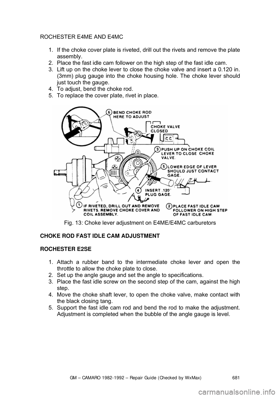
ROCHESTER E4ME AND E4MC
1. If the choke cover plate is riveted, drill out the rivets and remove the plate assembly.
2. Place the fast idle cam follower on t he high step of the fast idle cam.
3. Lift up on the choke lever to close the choke valve and insert a 0.120 i\
n. (3mm) plug gauge into the choke housi ng hole. The choke lever should
just touch the gauge.
4. To adjust, bend the choke rod.
5. To replace the cover plate, rivet in place.
Fig. 13: Choke lever adjustm ent on E4ME/E4MC carburetors
CHOKE ROD FAST IDLE CAM ADJUSTMENT
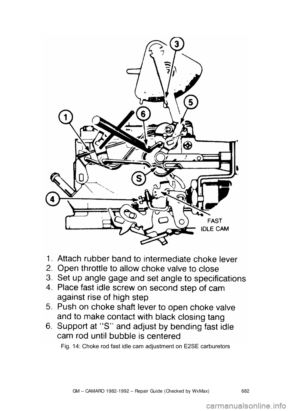
ROCHESTER E2SE 1. Attach a rubber band to the intermediate choke lever and open the
throttle to allow the choke plate to close.
2. Set up the angle gauge and set the angle to specifications.
3. Place the fast idle screw on the se cond step of the cam, against the high
step.
4. Move the choke shaft lever, to open the choke valve, make contact with
the black closing tang.
5. Support the fast idle cam rod and bend the rod to make the adjustment.
Adjustment is completed when the bubble of the angle gauge is level.
Page 682 of 875
GM – CAMARO 1982-1992 – Repair Guide (Checked by WxMax) 682
Fig. 14: Choke rod fast idle cam adjustment on E2SE carburetors
Page 683 of 875
GM – CAMARO 1982-1992 – Repair Guide (Checked by WxMax) 683
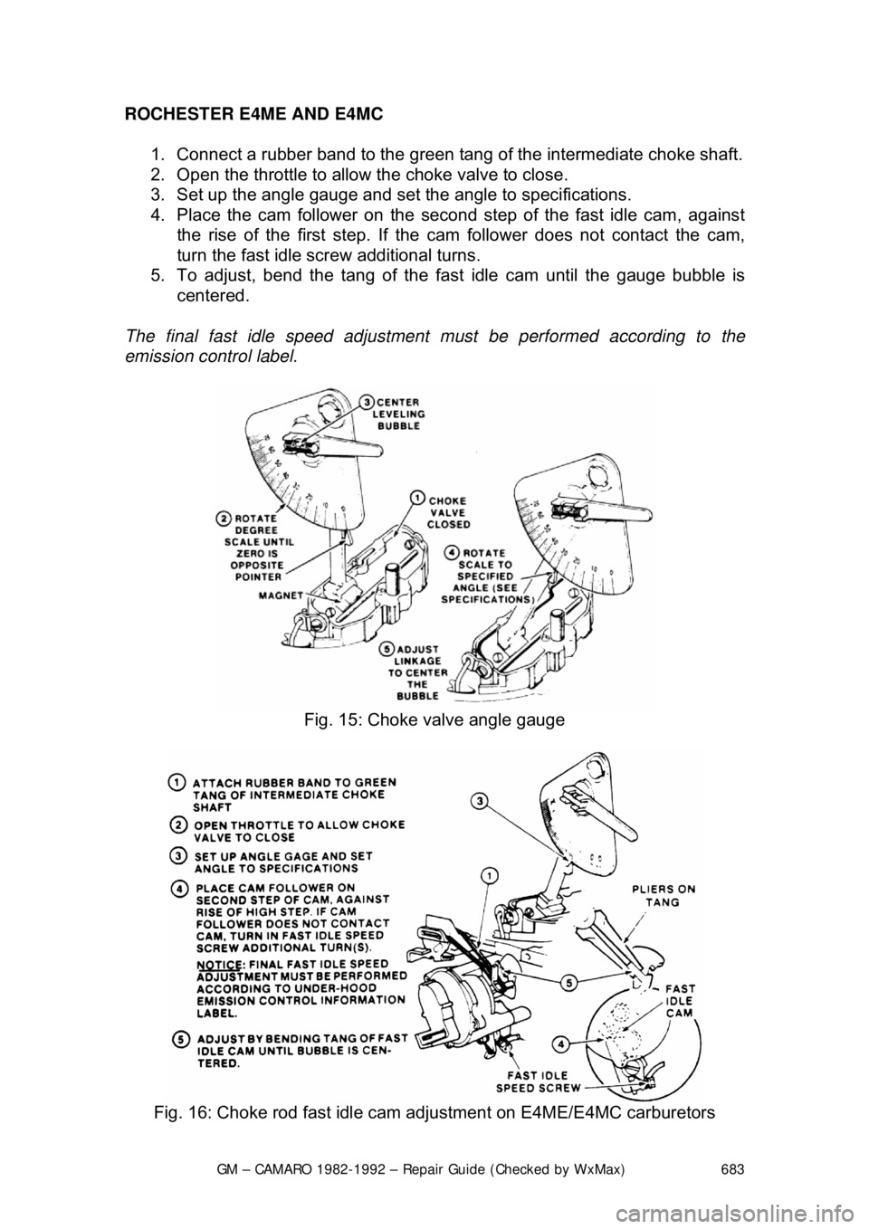
ROCHESTER E4ME AND E4MC
1. Connect a rubber band to the green tang of the intermediate choke shaft.
2. Open the throttle to allow the choke valve to close.
3. Set up the angle gauge and set the angle to specifications.
4. Place the cam follower on the second step of the fast idle cam, against
the rise of the first step. If the ca m follower does not contact the cam,
turn the fast idle screw additional turns.
5. To adjust, bend the tang of the fast idle cam until the gauge bubble is
centered.
The final fast idle speed adjustment must be performed according to the
emission control label.
Fig. 15: Choke valve angle gauge
Fig. 16: Choke rod fast idle cam adjustment on E4ME/E4MC carburetors
Page 684 of 875
GM – CAMARO 1982-1992 – Repair Guide (Checked by WxMax) 684
UNLOADER ADJUSTMENT
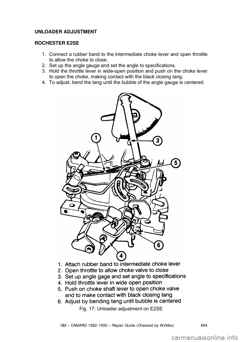
ROCHESTER E2SE
1. Connect a rubber band to the inte rmediate choke lever and open throttle
to allow the choke to close.
2. Set up the angle gauge and set the angle to specifications.
3. Hold the throttle leve r in wide-open position and push on the choke lever
to open the choke, making contact with the black closing tang.
4. To adjust, bend the tang until the bubble of the angle gauge is centered.
Fig. 17: Unloader adjustment on E2SE
Page 685 of 875
GM – CAMARO 1982-1992 – Repair Guide (Checked by WxMax) 685
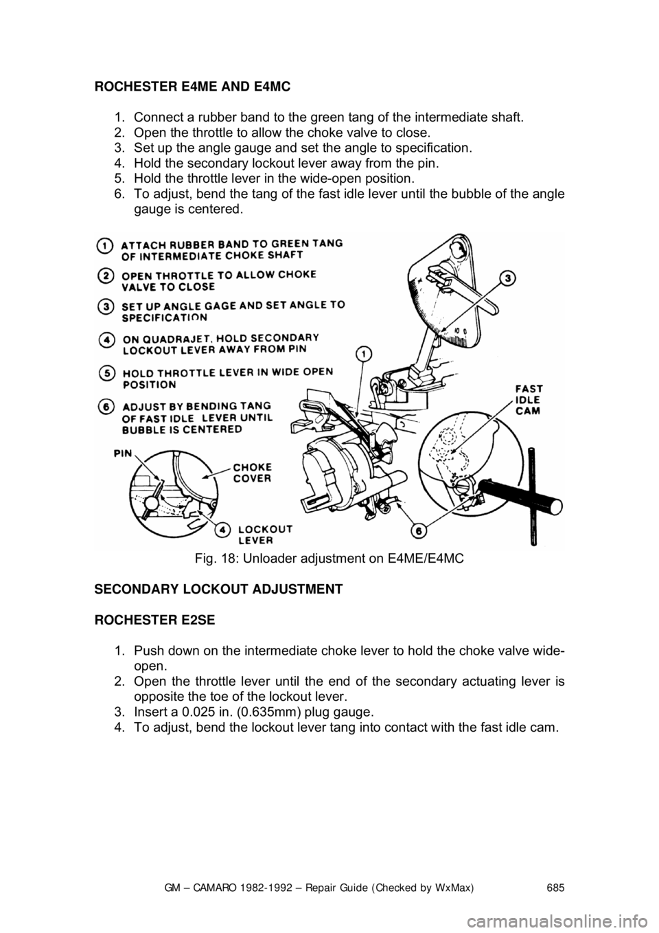
ROCHESTER E4ME AND E4MC
1. Connect a rubber band to the green tang of the intermediate shaft.
2. Open the throttle to allow the choke valve to close.
3. Set up the angle gauge and set the angle to specification.
4. Hold the secondary lockout lever away from the pin.
5. Hold the throttle lever in the wide-open position.
6. To adjust, bend the tang of the fast id le lever until the bubble of the angle
gauge is centered.
Fig. 18: Unloader adj ustment on E4ME/E4MC
SECONDARY LOCKOUT ADJUSTMENT
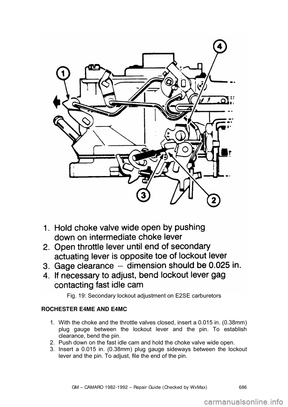
ROCHESTER E2SE 1. Push down on the inte rmediate choke lever to hold the choke valve wide-
open.
2. Open the throttle leve r until the end of the secondary actuating lever is
opposite the toe of t he lockout lever.
3. Insert a 0.025 in. (0.635mm) plug gauge.
4. To adjust, bend the lockout lever tang into contact with the fast idle cam.
Page 686 of 875
GM – CAMARO 1982-1992 – Repair Guide (Checked by WxMax) 686
Fig. 19: Secondary lockout adj ustment on E2SE carburetors
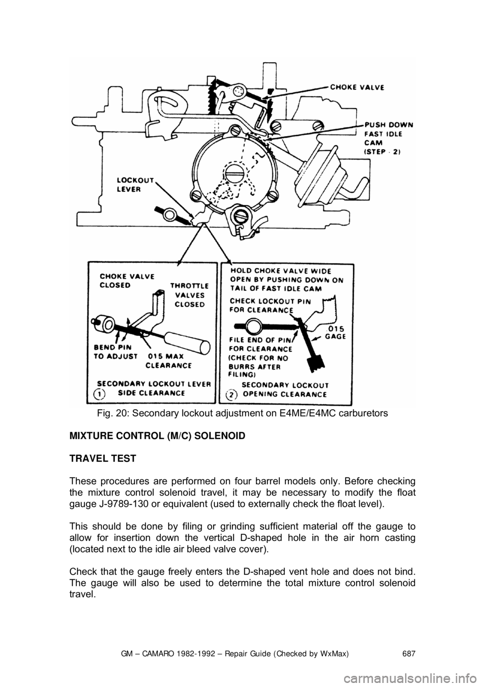
ROCHESTER E4ME AND E4MC 1. With the choke and the throttle valves closed, insert a 0.015 in. (0.38mm) plug gauge between the lockout lever and the pin. To establish
clearance, bend the pin.
2. Push down on the fast idle cam and hold the choke valve wide open.
3. Insert a 0.015 in. (0.38mm) pl ug gauge sideways between the lockout
lever and the pin. To adjust, file the end of the pin.
Page 687 of 875
GM – CAMARO 1982-1992 – Repair Guide (Checked by WxMax) 687
Fig. 20: Secondary lockout adjus tment on E4ME/E4MC carburetors
MIXTURE CONTROL (M/C) SOLENOID
TRAVEL TEST
These procedures are performed on four barrel models only. Before checking
the mixture control solenoid travel, it may be necessary to modify the float
gauge J-9789-130 or equivalent (used to ex ternally check the float level).
This should be done by filing or grinding sufficient material off the gauge to
allow for insertion down the vertical D-shaped hole in the air horn casting
(located next to the idle air bleed valve cover).
Check that the gauge freely enters the D-shaped vent hole and does not bind.
The gauge will also be used to determine t he total mixture control solenoid
travel.
Page 688 of 875
GM – CAMARO 1982-1992 – Repair Guide (Checked by WxMax) 688
With the engine OFF and the air cleaner re
moved, measure the control solenoid
travel as follows:
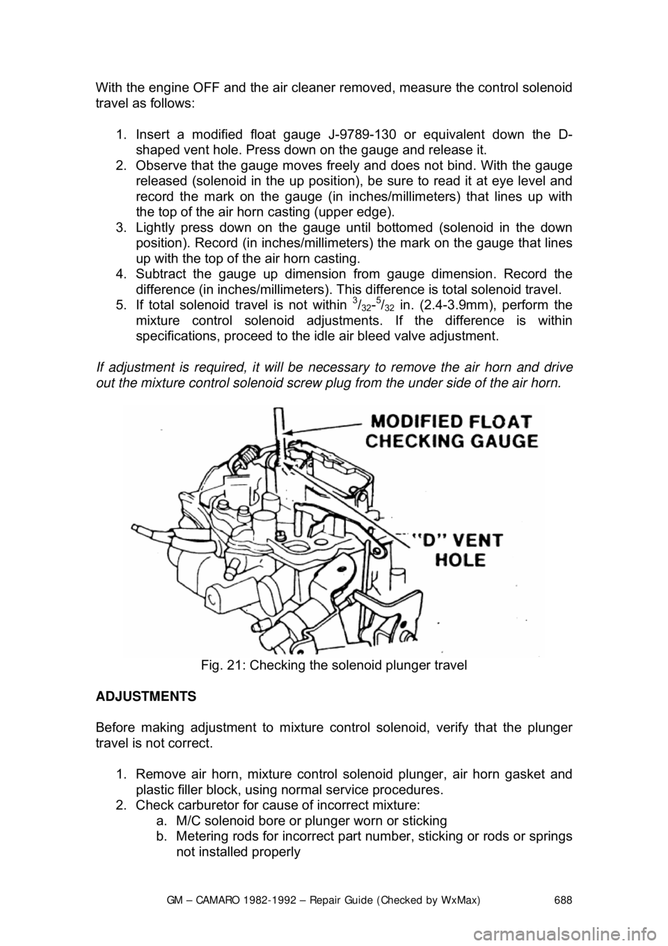
1. Insert a modified float gauge J- 9789-130 or equivalent down the D-
shaped vent hole. Press down on the gauge and release it.
2. Observe that the gauge moves freel y and does not bind. With the gauge
released (solenoid in the up position), be sure to read it at eye level and
record the mark on the gauge (in inc hes/millimeters) that lines up with
the top of the air hor n casting (upper edge).
3. Lightly press down on the gauge until bottomed (solenoid in the down
position). Record (in inches/millimeters) the mark on the gauge that lines
up with the top of the air horn casting.
4. Subtract the gauge up dimension from gauge dimension. Record the
difference (in inches/millimet ers). This difference is total solenoid travel.
5. If total solenoid travel is not within
3/32-5/32 in. (2.4-3.9mm), perform the
mixture control solenoid adjustment s. If the difference is within
specifications, proceed to the id le air bleed valve adjustment.
If adjustment is required, it will be necessary to remove the air horn and drive
out the mixture control solenoid screw pl ug from the under side of the air horn.
Fig. 21: Checking the solenoid plunger travel
ADJUSTMENTS
Before making adjustment to mixture cont rol solenoid, verify that the plunger
travel is not correct.
1. Remove air horn, mixture control solenoid plunger, air horn gasket and
plastic filler block, using normal service procedures.
2. Check carburetor for caus e of incorrect mixture:
a. M/C solenoid bore or plunger worn or sticking
b. Metering rods for incorrect part number, sticking or rods or springs
not installed properly
Page 689 of 875

GM – CAMARO 1982-1992 – Repair Guide (Checked by WxMax) 689
c. Foreign material in jets
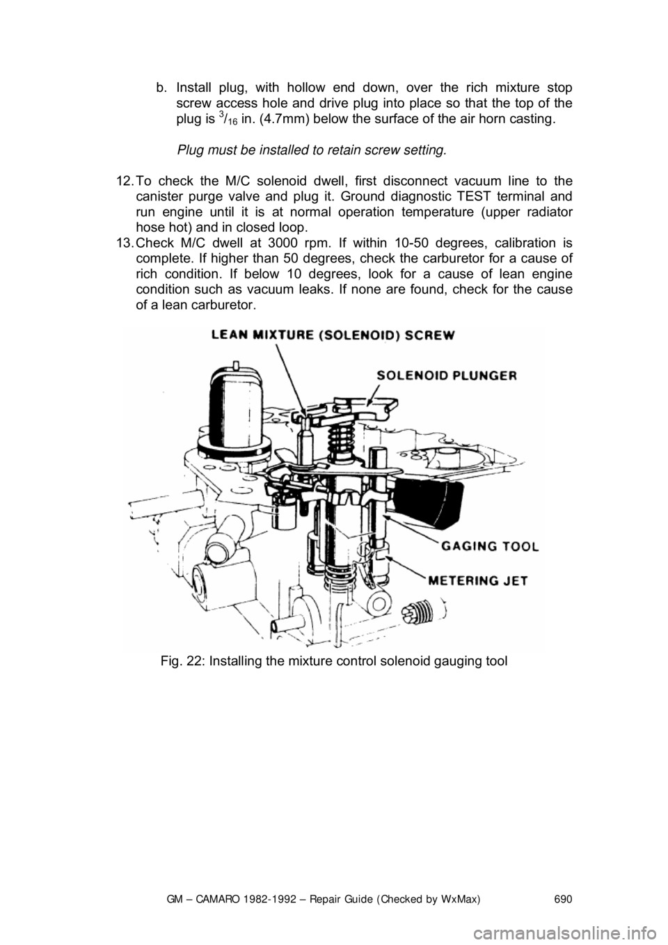
3. Remove throttle side metering rod. Install mixture control solenoid
gauging tool, J-33815-1, BT-8253-A, or equi valent, over the throttle side
metering jet rod guide and temporarily reinstall the solenoid plunger into
the solenoid body.
4. Holding the solenoid plunger in the DOWN position, use tool J-28696-10,
BT-7928, or equivalent, to turn lean mixture solenoid screw
counterclockwise until the plunger br eaks contact with the gauging tool.
Turn slowly clockwise until the pl unger makes contact with the gauging
tool. The adjustment is correct when t he solenoid plunger is contacting
both the solenoid stop and the gauging tool.
If the total difference in adjustment required less than
3/4 turn of the lean mixture
solenoid screw, the original setting was within the manufacturer's specifications.
5. Remove solenoid plunger and gaugi ng tool and reinstall metering rod
and plastic filler block.
6. Invert air horn and remove rich mixt ure stop screw from bottom side of
air horn, using tool J-28696-4, BT-7967-A, or equivalent.
7. Remove lean mixture screw plug and the rich mixture stop screw plug
from air horn, using a punch.
8. Reinstall rich mixtur e stop screw in air horn and bottom lightly, then back
screw out
1/4 turn.
9. Reinstall air horn gasket, mixture c ontrol solenoid plunger and air horn to
carburetor.
10. Adjust the M/C solenoid pl unger travel as follows:
a. Insert float gauge down D- shaped vent hole. Press down on
gauge and release, observing th at the gauge moves freely and
does not bind. With gauge released, (plunger UP position), read at
eye level and record the reading of the gauge mark (in
inches/millimeters) that lines up with the top of air horn casting,
(upper edge).
b. Lightly press dow n on gauge until bottomed, (plunger DOWN
position). Read and record (in inc hes/millimeters) the reading of
the gauge mark that lines up with top of air horn casting.
c. Subtract gauge UP position from the gauge DOWN position and
record the difference. This difference is the total plunger travel.
Insert external float gauge in vent hole and, with tool J-28696-10,
BT-7928, or equivalent, adjust rich mixture stop screw to obtain
5/32 in. (3.9mm) total plunger travel.
11. With solenoid plunger travel corre ctly set, install plugs (supplied in
service kits) in the air horn, as follows:
a. Install plug, hollow end down, into the access hole for the lean
mixture (solenoid) screw. Use suit ably sized punch to drive plug
into the air horn until t he top of plug is even with the lower. Plug
must be installed to retain the sc rew setting and to prevent fuel
vapor loss.
Page 690 of 875
GM – CAMARO 1982-1992 – Repair Guide (Checked by WxMax) 690
b. Install plug, with hollow end do
wn, over the rich mixture stop
screw access hole and drive plug into place so that the top of the
plug is
3/16 in. (4.7mm) below the surface of the air horn casting.
Plug must be installed to retain screw setting.
12. To check the M/C solenoid dwell, first disconnect vacuum line to the
canister purge valve and plug it. Ground diagnostic TEST terminal and
run engine until it is at normal operat ion temperature (upper radiator
hose hot) and in closed loop.
13. Check M/C dwell at 3000 rpm. If within 10-50 degrees, calibration is
complete. If higher than 50 degrees, chec k the carburetor for a cause of
rich condition. If below 10 degrees, look for a cause of lean engine
condition such as vacuum leaks. If none are found, check for the cause
of a lean carburetor.
Fig. 22: Installing the mixture control solenoid gauging tool