CHEVROLET CAMARO 1982 Repair Guide
Manufacturer: CHEVROLET, Model Year: 1982, Model line: CAMARO, Model: CHEVROLET CAMARO 1982Pages: 875, PDF Size: 88.64 MB
Page 661 of 875
GM – CAMARO 1982-1992 – Repair Guide (Checked by WxMax) 661
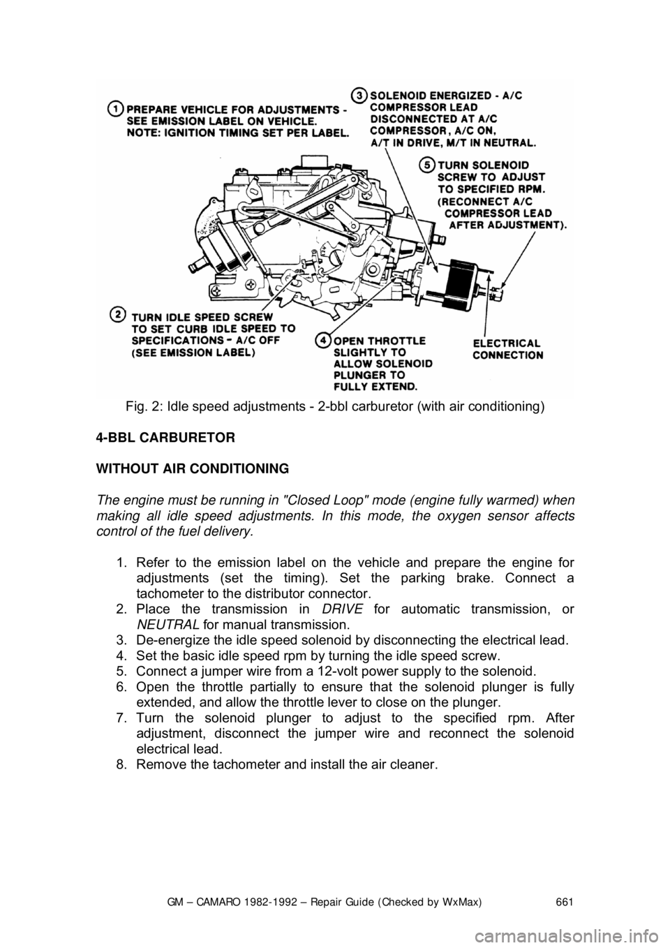
Fig. 2: Idle speed adjustm ents - 2-bbl carburetor (with air conditioning)
4-BBL CARBURETOR
WITHOUT AIR CONDITIONING
The engine must be running in "Closed Loop" mode (engine fully warmed) when
making all idle speed adjustments. In this mode, the oxygen sensor affects
control of the fuel delivery.
1. Refer to the emission label on the vehicle and prepare the engine for
adjustments (set the timing). Se t the parking brake. Connect a
tachometer to the dist ributor connector.
2. Place the transmission in DRIVE for automatic transmission, or
NEUTRAL for manual transmission.
3. De-energize the idle speed solenoid by disconnecting the electrical lead.
4. Set the basic idle speed rpm by turning the idle speed screw.
5. Connect a jumper wire from a 12-vo lt power supply to the solenoid.
6. Open the throttle partially to ensure that the solenoid plunger is fully
extended, and allow the throttle lever to close on the plunger.
7. Turn the solenoid plunger to adj ust to the specified rpm. After
adjustment, disconnect the jumper wire and reconnect the solenoid
electrical lead.
8. Remove the tachometer and install the air cleaner.
Page 662 of 875
GM – CAMARO 1982-1992 – Repair Guide (Checked by WxMax) 662
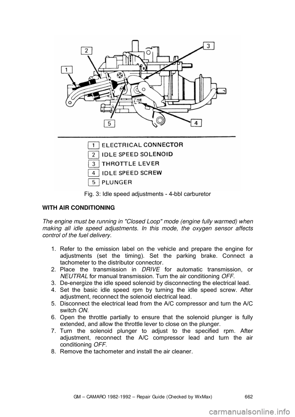
Fig. 3: Idle speed adjustm ents - 4-bbl carburetor
WITH AIR CONDITIONING
The engine must be running in "Closed Loop" mode (engine fully warmed) when
making all idle speed adjustments. In this mode, the oxygen sensor affects
control of the fuel delivery.
1. Refer to the emission label on the vehicle and prepare the engine for
adjustments (set the timing). Se t the parking brake. Connect a
tachometer to the dist ributor connector.
2. Place the transmission in DRIVE for automatic transmission, or
NEUTRAL for manual transmission. Tu rn the air conditioning OFF.
3. De-energize the idle speed solenoid by disconnecting the electrical lead.
4. Set the basic idle speed rpm by turning the idle speed screw. After
adjustment, reconnect the solenoid electrical lead.
5. Disconnect the electrical lead from the A/C compressor and turn the A/C
switch ON.
6. Open the throttle partially to ensure that the solenoid plunger is fully
extended, and allow the throttle lever to close on the plunger.
7. Turn the solenoid plunger to adj ust to the specified rpm. After
adjustment, reconnect the A/C co mpressor lead and turn the air
conditioning OFF.
8. Remove the tachometer and install the air cleaner.
Page 663 of 875
GM – CAMARO 1982-1992 – Repair Guide (Checked by WxMax) 663
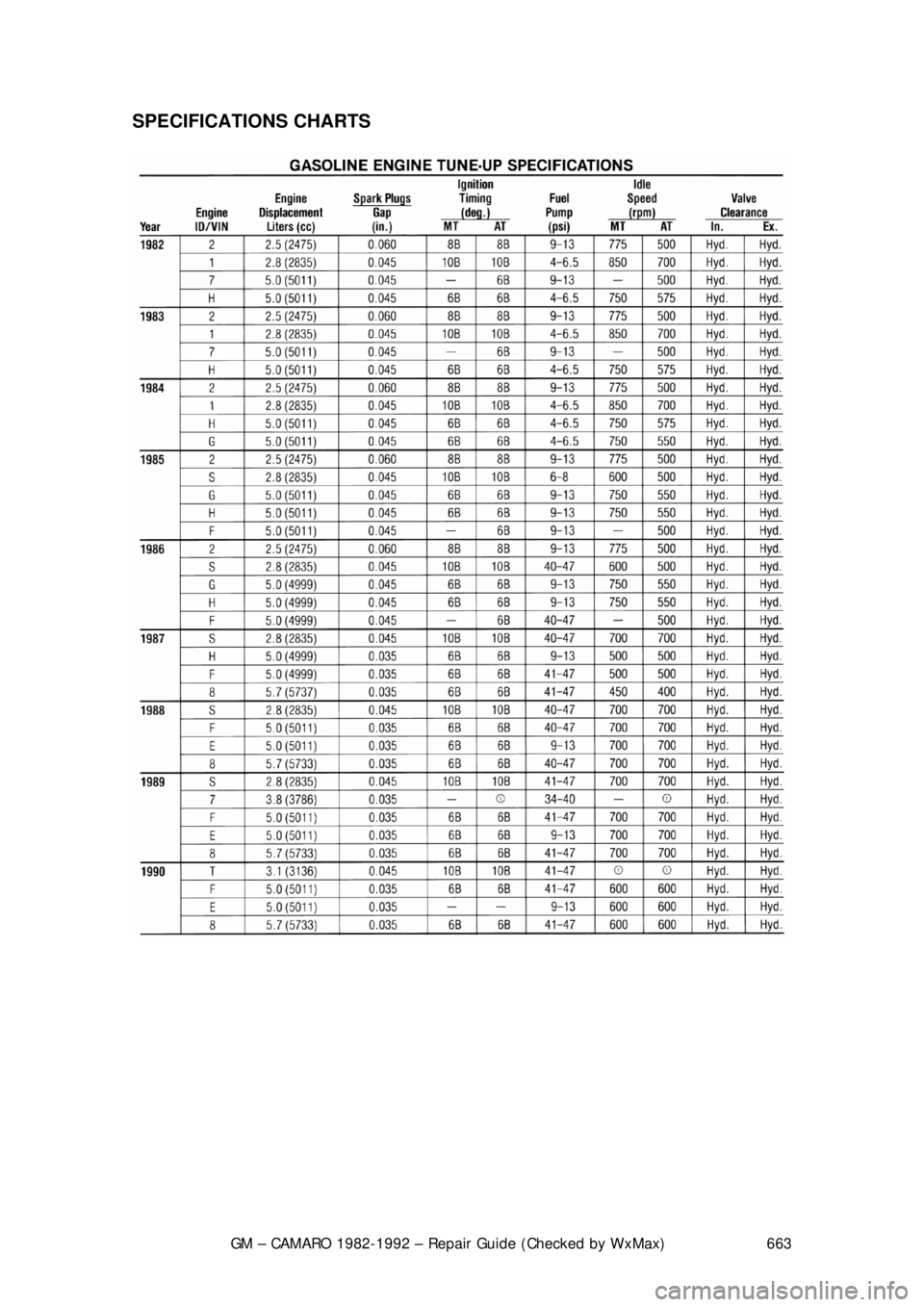
SPECIFICATIONS CHARTS
Page 664 of 875
GM – CAMARO 1982-1992 – Repair Guide (Checked by WxMax) 664
Page 665 of 875
GM – CAMARO 1982-1992 – Repair Guide (Checked by WxMax) 665
Page 666 of 875

GM – CAMARO 1982-1992 – Repair Guide (Checked by WxMax) 666
FUEL SYSTEM
BASIC FUEL SYSTEM DIAGNOSIS
When there is a problem star ting or driving a vehicle, two of the most important
checks involve the ignition and the fuel systems. The questions most mechanics
attempt to answer first, "is there spark?" an d "is there fuel?" will often lead to
solving most basic problems. For igni tion system diagnosis and testing, please
refer to the information on engine electr ical components and ignition systems
found earlier in this repair guide. If the ignition system checks out (there is
spark), then you must determine if the f uel system is operating properly (is there
fuel?).
CARBURETED FUEL SYSTEM
MECHANICAL FUEL PUMP
All fuel pumps used on carbureted V6 and V8 engines are of the diaphragm
type and are serviced by replacement onl y. No adjustments or repairs are
possible. The fuel pump is mounted on th e left front (V6) and right front (V8) of
the engine.
The fuel pumps are also equipped with vapor return lines for purposes of
emission control and to reduce vapor lock. All pumps are operated by an
eccentric on the camshaft. On V6 an d V8 engines, a pushrod between the
camshaft eccentric and the fuel pump operates the pump.
REMOVAL & INSTALLATION
When disconnecting the fuel pump outlet fitting, always use two wrenches to
avoid twisting the line.
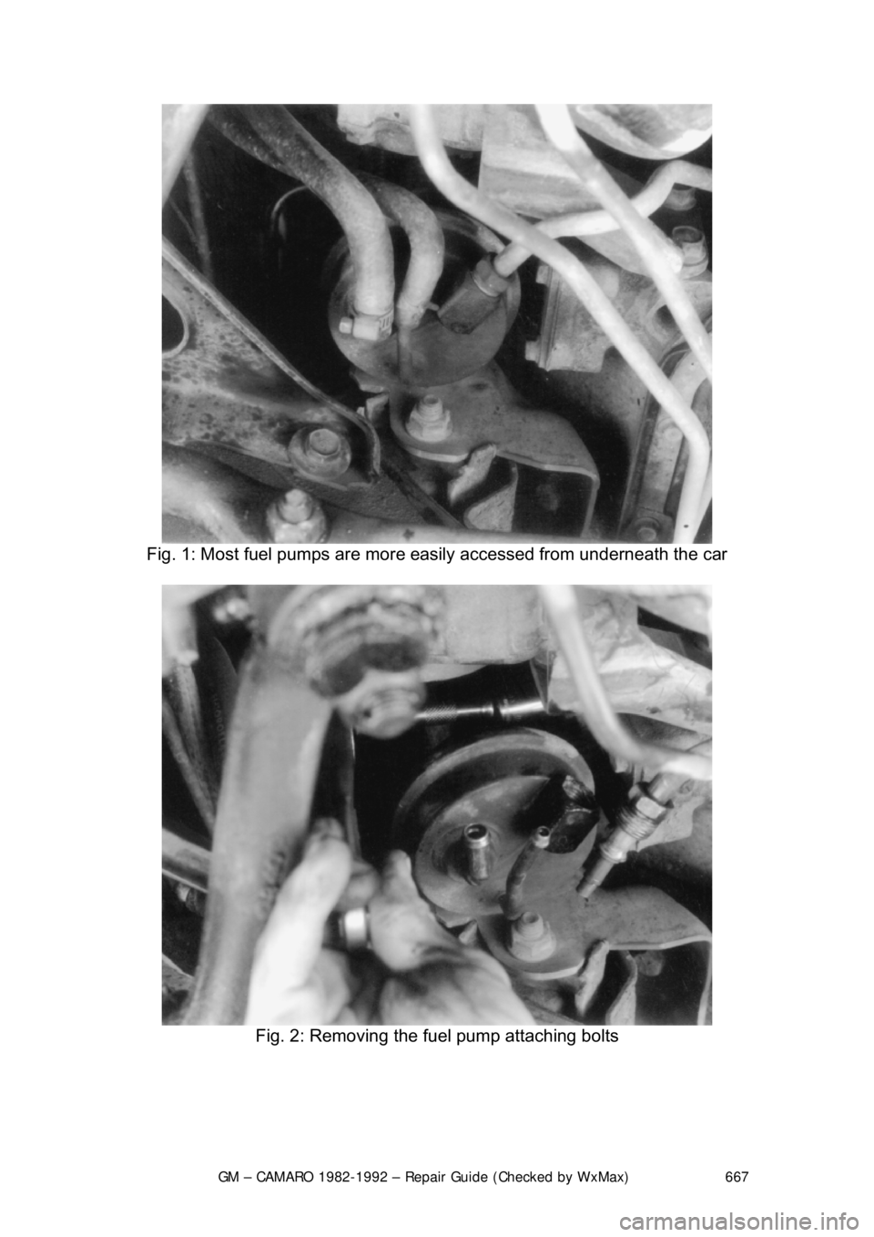
1. Disconnect the fuel in take and outlet lines at the pump, then plug the
pump intake line.
2. Remove the two pump mounting bol ts and lockwashers; remove the
pump and its gasket.
3. If the pump pushrod is to be remo ved from the V8, remove the two
adapter bolts and lockwashers, then re move the adapter and its gasket.
4. Install the fuel pump with a new gasket reversing the removal procedure.
Coat the mating surfaces with sealer.
5. Connect the fuel lines and check for leaks.
Page 667 of 875
GM – CAMARO 1982-1992 – Repair Guide (Checked by WxMax) 667
Fig. 1: Most fuel pumps are more easily accessed from underneath the car
Fig. 2: Removing the fuel pump attaching bolts
Page 668 of 875
GM – CAMARO 1982-1992 – Repair Guide (Checked by WxMax) 668
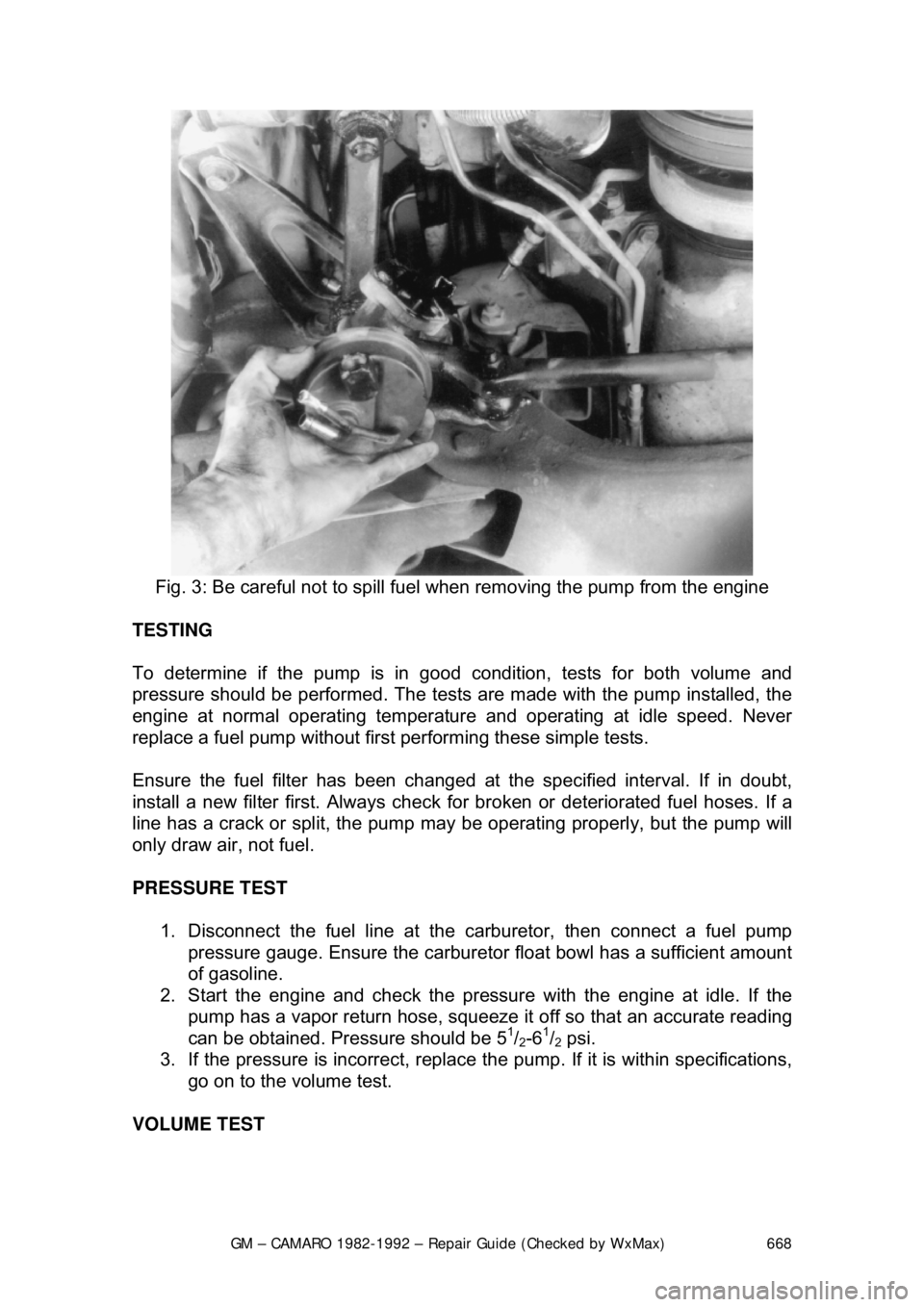
Fig. 3: Be careful not to spill fuel when removing the pump from the engine
TESTING
To determine if the pump is in good condition, tests for both volume and
pressure should be performed. The test s are made with the pump installed, the
engine at normal operating temperatur e and operating at idle speed. Never
replace a fuel pump without first performing these simple tests.
Ensure the fuel filter has been changed at the specified interval. If in doubt,
install a new filter first. Always check fo r broken or deteriorated fuel hoses. If a
line has a crack or split, the pump may be operating properly, but the pump will
only draw air, not fuel.
PRESSURE TEST
1. Disconnect the fuel line at the carburetor, then connect a fuel pump
pressure gauge. Ensure the carburet or float bowl has a sufficient amount
of gasoline.
2. Start the engine and c heck the pressure with the engine at idle. If the
pump has a vapor return hose, squeeze it off so that an accurate reading
can be obtained. Pressure should be 5
1/2-61/2 psi.
3. If the pressure is incorrect, replace t he pump. If it is within specifications,
go on to the volume test.
VOLUME TEST
Page 669 of 875

GM – CAMARO 1982-1992 – Repair Guide (Checked by WxMax) 669
1. Disconnect the pressure gauge. R
un the fuel line into a graduated
container.
2. Run the engine at idle until one pint of gasoline has been pumped. One
pint should be delivered in 30 seconds or less. There is normally enough
fuel in the carburetor float bowl to perform this test, but refill it if
necessary.
3. If the delivery rate is below the mini mum, check the lines for restrictions
or leaks, then r eplace the pump.
CARBURETORS
The V6 engine is equipped with the Ro chester E2SE carburetor, V8 engines
use the E4ME and E4MC. These carburet ors are of the downdraft design and
are used in conjunction with the CCC system for fuel cont rol. They have special
design features for optimum air/fuel mixt ure control during all ranges of engine
operation.
An electric solenoid in the carburetor controls the air/fu el ratio. The solenoid is
connected to an Electronic Control Module (ECM) which is an on-board
computer. The ECM provides a controllin g signal to the solenoid. The solenoid
controls the metering rod(s) and an id le air bleed valve, thereby closely
controlling the air/fuel ratio throughout the operating range of the engine.
MODEL IDENTIFICATION
General Motors Rochester carburetors ar e identified by their model code. The
first number indicates the number of ba rrels, while one of the last letters
indicates the type of choke used. These are V for the manifold mounted choke
coil, C for the choke coil mounted in the carburetor body, and E for electric
choke, also mounted on the carburetor. Model codes ending in A indicate an
altitude-compensatin g carburetor.
Because of their intricate nature and co mputer controls, the E2SE, E4ME and
E4MC carburetors should only be se rviced by a qualified technician.
PRELIMINARY CHECKS
The following should be observed befor e attempting any adjustments.
1. Thoroughly warm the engine. If the engine is cold, be sure that it reaches
operating temperature.
2. Check the torque of all carburet or mounting nuts and assembly screws.
Also check the intake manifold-to-cyli nder head bolts. If air is leaking at
any of these points, any attempts at adjustment will inevitably lead to
frustration.
3. Check the manifold heat control valve (if used) to be sure that it is free.
4. Check and adjust the choke as necessary.
5. Adjust the idle speed and mixture. If the mixture screws are capped,
don't adjust them unless all other c auses of rough idle have been
eliminated. If any adjustments are per formed that might possibly change
Page 670 of 875

GM – CAMARO 1982-1992 – Repair Guide (Checked by WxMax) 670
the idle speed or mixture,
adjust the idle and mixture again when you are
finished.
Before you make any carburetor adjustment s make sure that the engine is in
tune. Many problems which are thought to be carburetor related can be traced
to an engine which is simply out-of-tune. Any trouble in these areas will have
symptoms like those of carburetor problems.
ADJUSTMENTS
FAST IDLE
ROCHESTER E2SE 1. Refer to the emission label and pr epare the vehicle for adjustment.
2. Place the fast idle screw on the highest step of the fast idle cam.
3. Turn the fast idle screw to obtain the fast idle speed.
ROCHESTER E4ME AND E4MC
The fast idle adjustment must be perform ed according to the directions of the
emissions label.
FLOAT AND FUEL LEVEL
ROCHESTER E2SE
1. Remove the air horn and gasket.
2. While holding the retainer in place, push the float down lightly against the
needle.
3. Place a measuring gauge on the float at the farthest point from the float
hinge.
4. To adjust, remove the float and bend the arm up or down. Also check the
float alignment.
5. Install the air horn and gasket.