CHEVROLET CAMARO 1982 Repair Guide
Manufacturer: CHEVROLET, Model Year: 1982, Model line: CAMARO, Model: CHEVROLET CAMARO 1982Pages: 875, PDF Size: 88.64 MB
Page 721 of 875
GM – CAMARO 1982-1992 – Repair Guide (Checked by WxMax) 721
8. The idle speed should be 450-500 rpm, adjust as necessary.
WARNING - Correct minimum idle speed adj ustment is critical to vehicle
performance and component durability. Incorrect minimum idle speed
adjustment (too high) will caus e the IAC valve pintle to constantly bottom in it's
seat and result in early valve failure. If minimum idle speed is adjusted too low,
the vehicle may not start in cold weather or may stall during warm-up.
Turn the ignition OFF and reconnect the IAC motor connector.
9. Reconnect the distributor set-timing connector.
10. Use silicone sealant to co ver the throttle stop screw.
THROTTLE POSITION SENSOR (TPS)
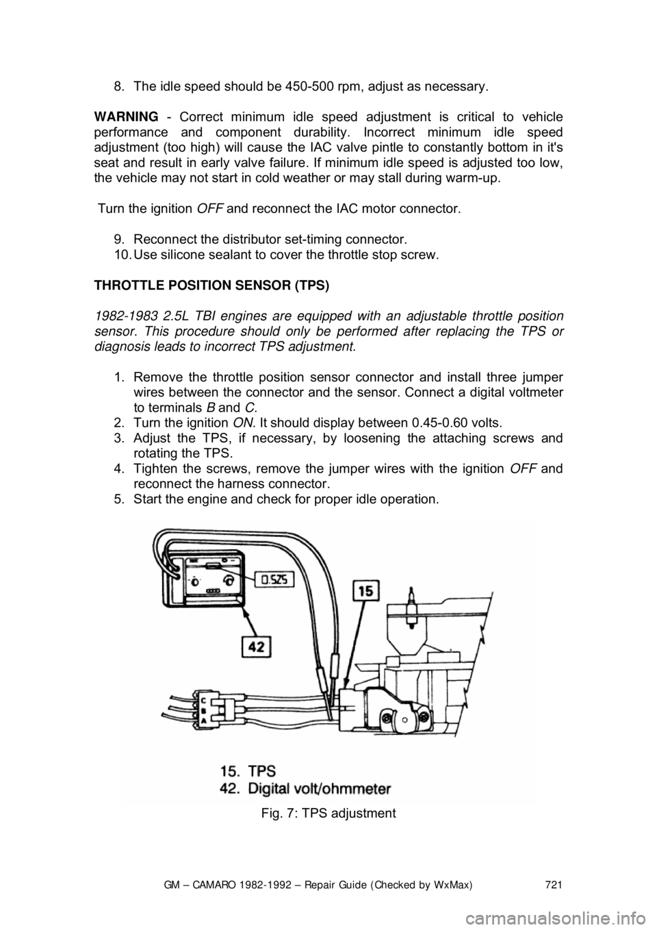
1982-1983 2.5L TBI engines ar e equipped with an adjustable throttle position
sensor. This procedure should only be performed after replacing the TPS or
diagnosis leads to incorrect TPS adjustment.
1. Remove the throttle position sensor connector and install three jumper wires between the connector and the s ensor. Connect a digital voltmeter
to terminals B and C.
2. Turn the ignition ON. It should display bet ween 0.45-0.60 volts.
3. Adjust the TPS, if necessary, by loosening the attaching screws and
rotating the TPS.
4. Tighten the screws, remove the jumper wires with the ignition OFF and
reconnect the harness connector.
5. Start the engine and check fo r proper idle operation.
Fig. 7: TPS adjustment
Page 722 of 875
GM – CAMARO 1982-1992 – Repair Guide (Checked by WxMax) 722
FUEL PRESSURE REGULATOR
REMOVAL & INSTALLATION
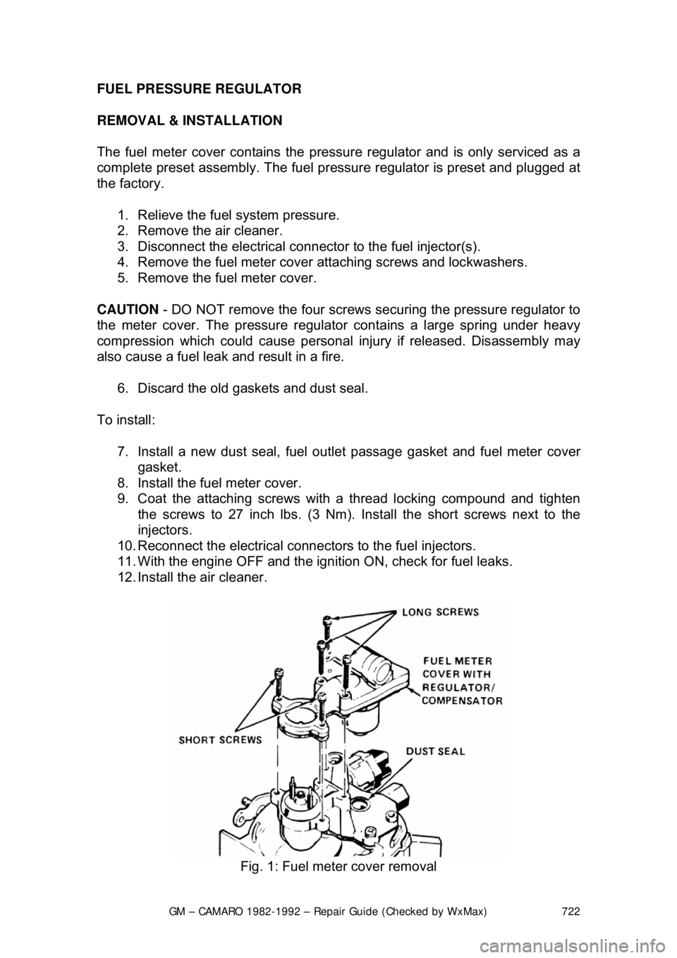
The fuel meter cover contains the pressu
re regulator and is only serviced as a
complete preset assembly. The fuel pressu re regulator is preset and plugged at
the factory.
1. Relieve the fuel system pressure.
2. Remove the air cleaner.
3. Disconnect the electrical connec tor to the fuel injector(s).
4. Remove the fuel meter cover attaching screws and lockwashers.
5. Remove the fuel meter cover.
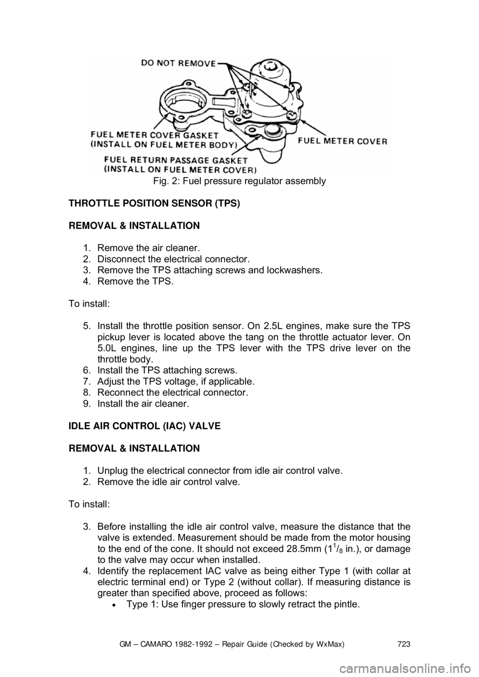
CAUTION - DO NOT remove the four screws se curing the pressure regulator to
the meter cover. The pressure regulat or contains a large spring under heavy
compression which could cause personal injury if released. Disassembly may
also cause a fuel leak and result in a fire.
6. Discard the old gaskets and dust seal.
To install: 7. Install a new dust seal, fuel outlet passage gasket and fuel meter cover\
gasket.
8. Install the fuel meter cover.
9. Coat the attaching screws with a thread locking compound and tighten the screws to 27 inch lbs. (3 Nm). Install the short screws next to the
injectors.
10. Reconnect the electrical connec tors to the fuel injectors.
11. With the engine OFF and the igniti on ON, check for fuel leaks.
12. Install the air cleaner.
Fig. 1: Fuel meter cover removal
Page 723 of 875
GM – CAMARO 1982-1992 – Repair Guide (Checked by WxMax) 723
Fig. 2: Fuel pressure regulator assembly
THROTTLE POSITION SENSOR (TPS)
REMOVAL & INSTALLATION 1. Remove the air cleaner.
2. Disconnect the electrical connector.
3. Remove the TPS attaching screws and lockwashers.
4. Remove the TPS.
To install: 5. Install the throttle position sensor. On 2.5L engines, make sure the TPS pickup lever is located above the tang on the throttle actuator lever. On
5.0L engines, line up the TPS lever with the TPS drive lever on the
throttle body.
6. Install the TPS attaching screws.
7. Adjust the TPS volt age, if applicable.
8. Reconnect the electrical connector.
9. Install the air cleaner.
IDLE AIR CONTROL (IAC) VALVE
REMOVAL & INSTALLATION 1. Unplug the electrical connector from idle air control valve.
2. Remove the idle air control valve.
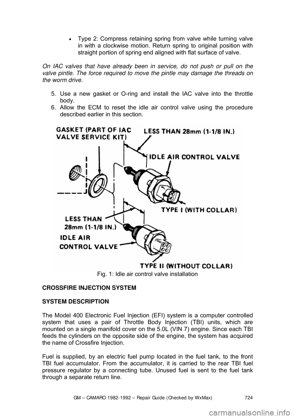
To install: 3. Before installing the idle air contro l valve, measure the distance that the
valve is extended. Measurement s hould be made from the motor housing
to the end of the cone. It should not exceed 28.5mm (1
1/8 in.), or damage
to the valve may occur when installed.
4. Identify the replacement IAC valve as being either Type 1 (with collar at
electric terminal end) or Type 2 (without collar). If measuring distance is
greater than specified abov e, proceed as follows:
• Type 1: Use finger pressure to slowly retract the pintle.
Page 724 of 875
GM – CAMARO 1982-1992 – Repair Guide (Checked by WxMax) 724
•
Type 2: Compress retaining spring from valve while turning valve
in with a clockwise motion. Return spring to original position with
straight portion of spring end aligned with flat surface of valve.
On IAC valves that have already been in service, do not push or pull on the
valve pintle. The force required to move the pintle may damage the threads on
the worm drive.
5. Use a new gasket or O-ring and install the IAC valve into the throttle body.
6. Allow the ECM to reset the idle air control valve using the procedure
described earlier in this section.
Fig. 1: Idle air control valve installation
CROSSFIRE INJECTION SYSTEM
SYSTEM DESCRIPTION
The Model 400 Electronic Fuel Injection (EFI) system is a computer controlled
system that uses a pair of Throttle Body Injection (TBI) units, which are
mounted on a single manifold cover on t he 5.0L (VIN 7) engine. Since each TBI
feeds the cylinders on the opposite side of the engine, the system has acquired
the name of Crossf ire Injection.
Fuel is supplied, by an electric fuel pum p located in the fuel tank, to the front
TBI fuel accumulator. From the accumulator, it is carried to the rear TBI fuel
pressure regulator by a c onnecting tube. Unused fuel is sent to the fuel tank
through a separate return line.
Page 725 of 875
GM – CAMARO 1982-1992 – Repair Guide (Checked by WxMax) 725
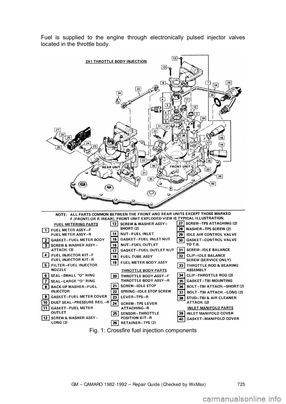
Fuel is supplied to the engine through
electronically pulsed injector valves
located in the throttle body.
Fig. 1: Crossfire fuel injection components
Page 726 of 875

GM – CAMARO 1982-1992 – Repair Guide (Checked by WxMax) 726
RELIEVING FUEL SYSTEM PRESSURE
1. Remove the fuse marked "Fuel Pu mp" from the fuse block in the
passenger compartment.
2. Crank the engine. Th e engine will start and run until the fuel supply
remaining in the lines is exhauste d. When the engines stops, engage the
starter again for three seconds to a ssure dissipation of any remaining
pressure.
3. With the ignition OFF, disconnect the negative battery cable to prevent
fuel discharge if the key is accidentally turned to the ON position.
Replace the fuse with the ignition OFF.
When disconnecting fuel lines, there ma y still be a small amount of fuel
released. Cover the fuel line connection wi th a shop cloth to collect the fuel,
then place the cloth in an approved container.
ELECTRIC FUEL PUMP
REMOVAL & INSTALLATION
The removal and installation procedures fo r the Crossfire injection system fuel
pump is identical to the Throttle Body In jection (TBI) system. Please refer to the
TBI fuel pump procedures earlier in this repair guide.
TESTING
The testing procedures for the Crossfire in jection system fuel pump is identical
to the Throttle Body Injection (TBI) syst em. Please refer to the TBI fuel pump
procedures earlier in this repair guide.
THROTTLE BODY
REMOVAL & INSTALLATION
FRONT UNIT
1. Relieve the fuel system pressure.
2. Remove the air cleaner assembly, noting the connection points of the
vacuum lines.
3. Detach the electrical connectors at the injector and the idle air control
motor.
4. Disconnect the vacuum lines from the TBI unit, noting the connection
points. During installation, refer to the underhood emission control
information decal for vacuum line routing information.
5. Disconnect the transmission det ent cable from the TBI unit.
6. Disconnect the fuel inlet (feed) and fuel balance line connections at the
front TBI unit.
7. Remove and discard the throttle cont rol rod retaining clip from the front
TBI throttle lever stud. A new clip must be used during reassembly.
8. Unbolt and remove the TBI unit.
Page 727 of 875

GM – CAMARO 1982-1992 – Repair Guide (Checked by WxMax) 727
To install:
9. Replacement of the manifold cover or either throttle body requires throttle
valve synchronizing and checking of the throttle rod alignment (see
"Preliminary Adjustments"). Before installing the replacement throttle
body unit(s) on the engine, perform the following steps:
a. If the tamper resistant plugs co vering the throttle stop screws are
in place, remove the plugs.
b. If the front TBI unit throttle syn chronizing screw has a welded
retaining collar, grind off the weld.
c. Block possible movement of the throttle lever, relieving the force
of the heavy spring against the throttle synchronizing screw. This
prevents the levers from coming into contact.
If the lever is not blocked before the thro ttle synchronizing screw is removed,
the screw may be damaged, and reinstallation will be accomplished only with
great difficulty.
d. Remove the synchronizing screw and collar. Discard the collar and reinstall the screw. The blocking from the throttle lever (installed in the
previous step) can now be removed.
CAUTION - The collar must be removed to prevent possible interference with
the air cleaner. Failure to do so c ould result in personal injury
10. Use new gaskets and tighten the TB I bolts to 120-168 inch lbs. (13-19
Nm) during installation.
11. Perform the preliminary adjustm ents. These procedures must be
followed before further assembly.
12. Reconnect the fuel lines to the TBI units. Use a backup wrench to
prevent the nuts from tu rning in the TBI unit.
13. Reconnect the throttle cable and detent cable.
14. Reconnect all related vacuum lines.
15. Reconnect the electrical connectors.
16. With the engine OFF, depress the accelerator pedal to the floor and
release. Check for free return of the pedal.
17. Check the throttle position sensor voltage and adjust if necessary.
18. Perform the Minimum Idle and Thro ttle Valve Synchronization adjustment
procedures.
Rear Unit 1. Relieve the fuel system pressure.
2. Remove the air cleaner assembly, noting the connection points of the
vacuum lines.
3. Disconnect the electrical connectors at the injector, idle air control motor,
and throttle position sensor.
4. Disconnect the vacuum lines from the TBI unit, noting the connection
points. During installation, refer to the underhood emission control
information decal for vacuum line routing information.
Page 728 of 875

GM – CAMARO 1982-1992 – Repair Guide (Checked by WxMax) 728
5. Disconnect the throttle and cruise c
ontrol (if so equipped) cables at the
TBI unit.
6. Disconnect the fuel return and bal ance line connections from the rear TBI
unit.
7. Remove and discard the throttle cont rol rod retaining clip from the front
TBI unit throttle lever stud. A new clip must be used during reassembly.\
One throttle rod end bearing is permanently attached to the throttle lever stud of
the rear TBI unit, and must not be remov ed from it. If the throttle rod and
bearing assembly needs replacement, Th e entire rear throttle body must be
replaced.
8. Unbolt and remove the TBI unit.
To install: 9. Replacement of the manifold cover or either throttle body requires throttle
valve synchronizing and checking of the throttle rod alignment (see
"Preliminary Adjustments"). Before installing the replacement throttle
body unit(s) on the engine, perform the following steps:
a. If the tamper resistant plugs co vering the throttle stop screws are
in place, remove the plugs.
b. If the front TBI unit throttle syn chronizing screw has a welded
retaining collar, grind off the weld.
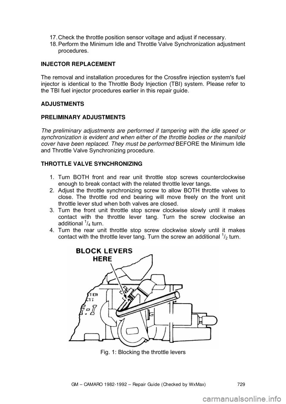
c. Block possible movement of the throttle lever, relieving the force
of the heavy spring against the throttle synchronizing screw. This
prevents the levers from coming into contact.
If the lever is not blocked before the thro ttle synchronizing screw is removed,
the screw may be damaged, and reinstallation will be accomplished only with
great difficulty.
d. Remove the synchronizing screw and collar. Discard the collar and reinstall the screw. The blocking from the throttle lever (installed in the
previous step) can now be removed.
CAUTION - The collar must be removed to prevent possible interference with
the air cleaner. Failure to do so c ould result in personal injury.
10. Use new gaskets and tighten the TB I bolts to 120-168 inch lbs. (13-19
Nm) during installation.
11. Perform the preliminary adjustm ents. These procedures must be
followed before further assembly.
12. Reconnect the fuel lines to the TBI units. Use a backup wrench to
prevent the nuts from tu rning in the TBI unit.
13. Reconnect the throttle cable and the cruise control cable.
14. Reconnect all related vacuum lines.
15. Reconnect the electrical connectors.
16. With the engine OFF, depress t he accelerator pedal to the floor and
release. Check for free return of the pedal.
Page 729 of 875
GM – CAMARO 1982-1992 – Repair Guide (Checked by WxMax) 729
17. Check the throttle position sensor voltage and adjust if necessary.
18. Perform the Minimum Idle and Thro
ttle Valve Synchronization adjustment
procedures.
INJECTOR REPLACEMENT
The removal and installation procedures fo r the Crossfire injection system's fuel
injector is identical to the Throttle Bo dy Injection (TBI) system. Please refer to
the TBI fuel injector procedures earlier in this repair guide.
ADJUSTMENTS
PRELIMINARY ADJUSTMENTS
The preliminary adjustments are performed if tampering with the idle speed or
synchronization is evident and when either of the throttle bodies or the manifold
cover have been replaced. They must be performed BEFORE the Minimum Idle
and Throttle Valve Synchronizing procedure.
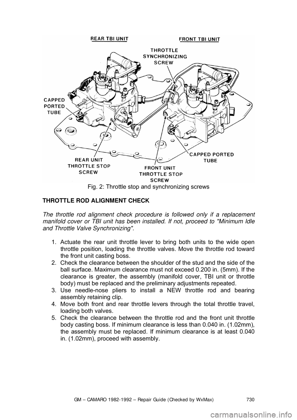
THROTTLE VALVE SYNCHRONIZING
1. Turn BOTH front and rear unit throttle stop screws counterclockwise enough to break contact with the related throttle lever tangs.
2. Adjust the throttle synchronizing scr ew to allow BOTH throttle valves to
close. The throttle rod end bearing w ill move freely on the front unit
throttle lever stud when both valves are closed.
3. Turn the front unit th rottle stop screw clockwise slowly until it makes
contact with the throttle lever tang. Turn the screw clockwise an
additional
1/4 turn.
4. Turn the rear unit throttle stop screw clockwise slowly until it makes
contact with the throttle lever t ang. Turn the screw an additional
1/2 turn.
Fig. 1: Blocking the throttle levers
Page 730 of 875
GM – CAMARO 1982-1992 – Repair Guide (Checked by WxMax) 730
Fig. 2: Throttle stop and synchronizing screws
THROTTLE ROD ALIGNMENT CHECK
The throttle rod alignment check procedur e is followed only if a replacement
manifold cover or TBI unit has been inst alled. If not, proceed to "Minimum Idle
and Throttle Valve Synchronizing".
1. Actuate the rear unit throttle leve r to bring both units to the wide open
throttle position, loading the throttle valves. Move the throttle rod toward
the front unit casting boss.
2. Check the clearance bet ween the shoulder of the stud and the side of the
ball surface. Maximum clearance must not exceed 0.200 in. (5mm). If the
clearance is greater, the assembly (mani fold cover, TBI unit or throttle
body) must be replaced and the pr eliminary adjustments repeated.
3. Use needle-nose pliers to inst all a NEW throttle rod and bearing
assembly retaining clip.
4. Move both front and rear throttle le vers through the total throttle travel,
loading both valves.
5. Check the clearance bet ween the throttle rod and the front unit throttle
body casting boss. If minimum clearanc e is less than 0.040 in. (1.02mm),
the assembly must be replaced. If minimum clearance is at least 0.040
in. (1.02mm), proceed with assembly.