CHEVROLET CAMARO 1982 Repair Guide
Manufacturer: CHEVROLET, Model Year: 1982, Model line: CAMARO, Model: CHEVROLET CAMARO 1982Pages: 875, PDF Size: 88.64 MB
Page 641 of 875

GM – CAMARO 1982-1992 – Repair Guide (Checked by WxMax) 641
If, however, there is no spark or a weak
spark, then further ignition system
testing will have to be done. Troubleshooting techniques fall into various
categories, depending on t he nature of the problem and the system being
tested. Categories will include symptom s such as the engine cranks, but will not
start or the engine runs rough.
HEI SYSTEM
When testing the HEI system, there are 2 major categories of problems, (1)
Engine cranks, but will not star t or (2) Engine runs, but runs rough or cuts out.
If the engine will not start, perform a spar k test as described earlier. This will
narrow the problem area down considerab ly. If no spark occurs, check for the
presence of normal battery voltage at the battery ( BAT) terminal on the ignition
coil. The ignition switch must be in the ON position for this test. Either a
voltmeter or a test light wire may be us ed for this test. Connect the test light
wire to ground and the probe end to the BAT terminal at the coil. If the light
comes on, you have voltage to the distribut or and/or spark plug wires. If the light
fails to come on, this indicates an open circuit in the ignition primary wiring
leading to the distributor. In this case , you will have to check wiring continuity
back to the ignition switch using a test li ght. If there is battery voltage at the BAT
terminal, but no spark at the plugs, t hen the problem probably lies within the
distributor assembly.
If, on the other hand, the engine starts, but runs roughly or cuts out, make sure
the plug wires are in good shape first. There should be no obvious cracks or
breaks. You can check the plug wires with an ohmmeter, but do not pierce the
wires with a probe. Check the chart for th e correct plug wire resistance. If the
plug wires are OK, remove the cap asse mbly and check for moisture, cracks,
chips, or carbon tracks, or any other hi gh voltage leads or failures. Replace the
cap if any defects are found. Make su re the timer wheel rotates when the
engine is cranked.
If the trouble has been narrowed down to t he units within the distributor, the
following tests can help pinpoint the defective component. An ohmmeter with
both high and low ranges shou ld be used. These tests are made with the cap
assembly removed and the battery wir e disconnected. If a tachometer is
connected to the TACH terminal, disconnect it before making these tests.
IGNITION COIL
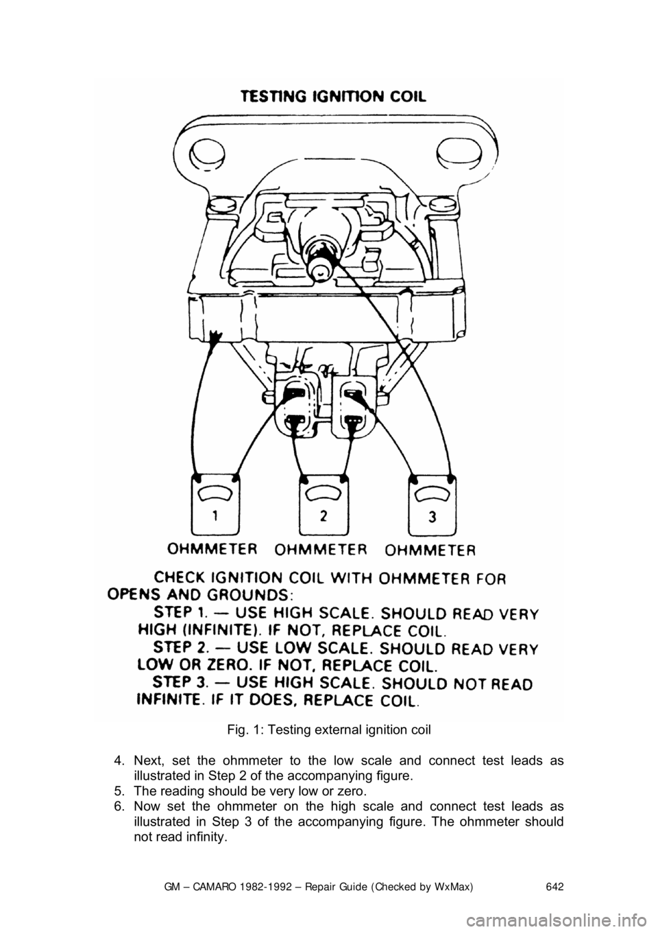
EXTERNALLY MOUNTED 1. Disconnect the coil wires and se t the ohmmeter on the high scale.
2. Connect the ohmmeter to the ignition co il as illustrated in Step 1 of the
accompanying figure.
3. The ohmmeter should read near infinite or very high.
Page 642 of 875
GM – CAMARO 1982-1992 – Repair Guide (Checked by WxMax) 642
Fig. 1: Testing exte rnal ignition coil
4. Next, set the ohmmete r to the low scale and connect test leads as
illustrated in Step 2 of t he accompanying figure.
5. The reading should be very low or zero.
6. Now set the ohmmeter on the high scale and connect test leads as illustrated in Step 3 of the accom panying figure. The ohmmeter should
not read infinity.
Page 643 of 875
GM – CAMARO 1982-1992 – Repair Guide (Checked by WxMax) 643
7. If any results of the 3 tests lis
ted above do not agree with the desired
readings, replace the ignition coil.
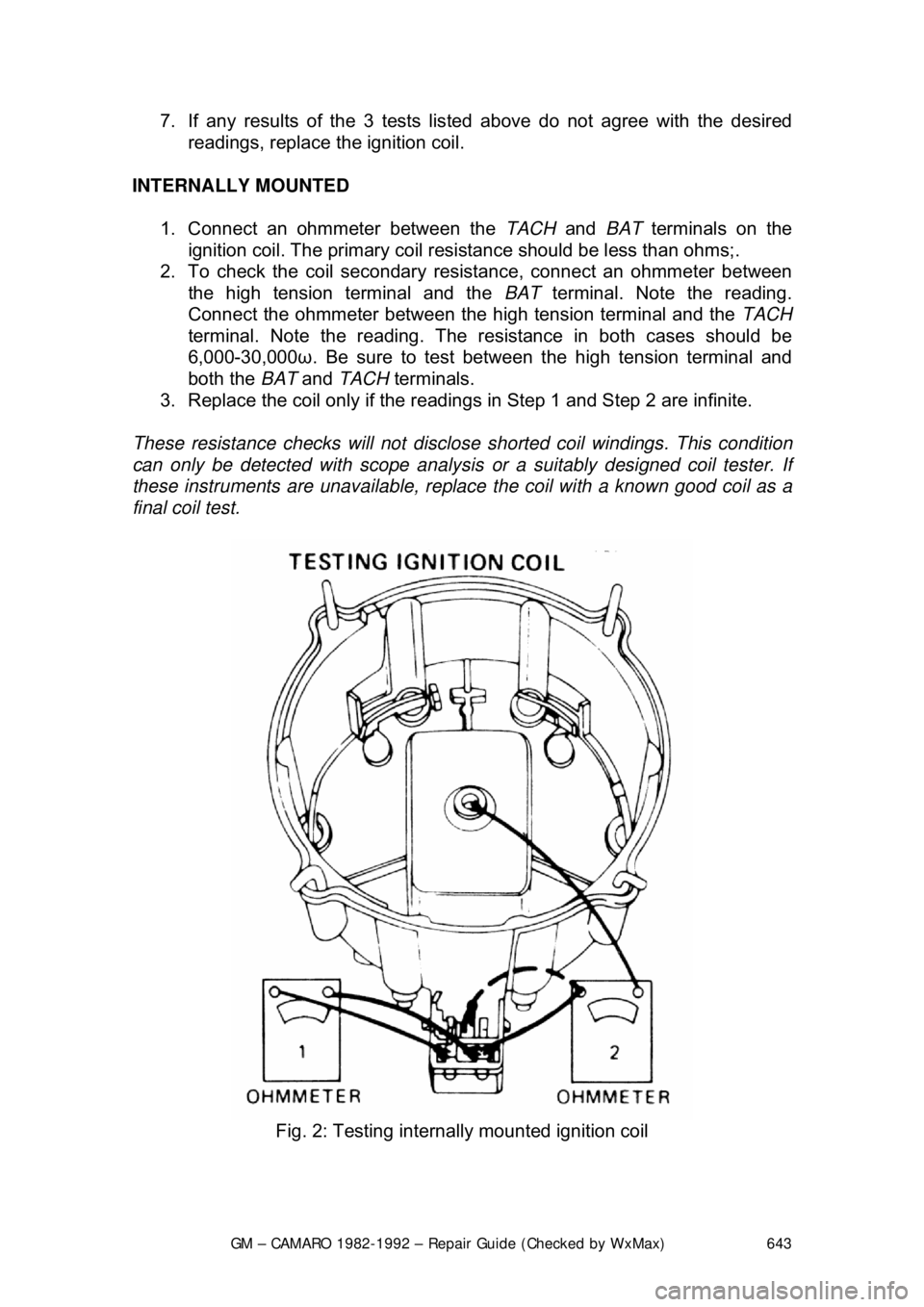
INTERNALLY MOUNTED 1. Connect an ohmmeter between the TACH and BAT terminals on the
ignition coil. The primary coil resi stance should be less than ohms;.
2. To check the coil secondary resistance, connect an ohmmeter between the high tension terminal and the BAT terminal. Note the reading.
Connect the ohmmeter between the high tension terminal and the TACH
terminal. Note the reading. The resi stance in both cases should be
6,000-30,000 ω. Be sure to test between the high tension terminal and
both the BAT and TACH terminals.
3. Replace the coil only if the reading s in Step 1 and Step 2 are infinite.
These resistance checks will not disclose shorted coil windings. This condition
can only be detected with scope analysis or a suitably designed coil tester. If
these instruments are unavaila ble, replace the coil with a known good coil as a
final coil test.
Fig. 2: Testing interna lly mounted ignition coil
Page 644 of 875
GM – CAMARO 1982-1992 – Repair Guide (Checked by WxMax) 644
PICKUP COIL
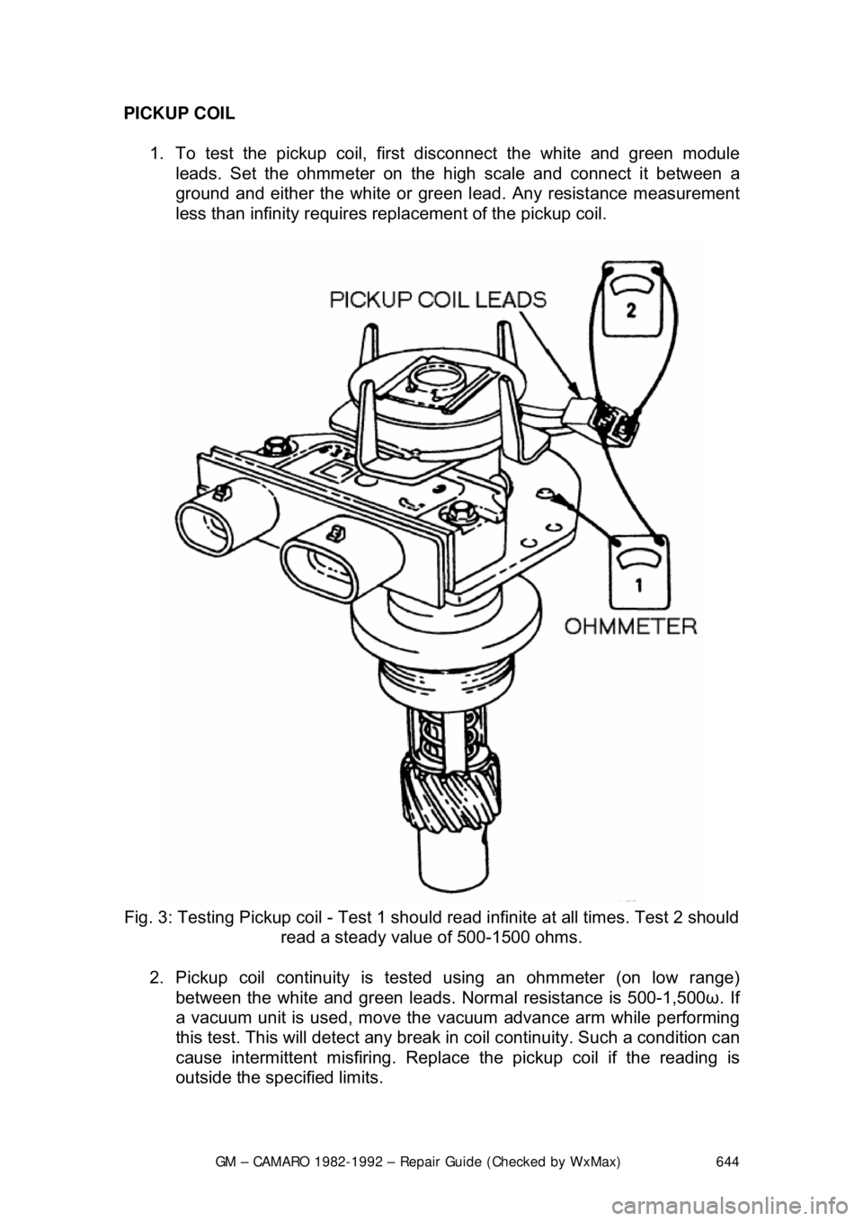
1. To test the pickup coil, firs t disconnect the white and green module
leads. Set the ohmmeter on the high scale and connect it between a
ground and either the wh ite or green lead. Any resistance measurement
less than infinity requires repl acement of the pickup coil.
Fig. 3: Testing Pickup coil - Test 1 should read infinite at all times. Test 2 should
read a steady value of 500-1500 ohms.
2. Pickup coil continuity is test ed using an ohmmeter (on low range)
between the white and gr een leads. Normal resistance is 500-1,500ω. If
a vacuum unit is used, move the vacuum advance arm while performing
this test. This will detect any break in coil continuity. Such a condition can
cause intermittent misfiring. Replac e the pickup coil if the reading is
outside the specified limits.
Page 645 of 875

GM – CAMARO 1982-1992 – Repair Guide (Checked by WxMax) 645
3. If no defects have been found at this
time, and you still have a problem,
then the module will have to be che cked. If you do not have access to a
module tester, the only possible alter native is a substitution test. If the
module fails the substitution test, replace it.
COMPONENT REPLACEMENT
CAUTION - When handling secondar y spark plug leads with the engine running
or starting, insulated pliers must be used and care exercised to prevent a
possible electrical shock.
HEI SYSTEM
IGNITION COIL
EXTERNALLY MOUNTED
1. Disconnect the negative battery cable.
2. Disconnect the ignition coil wire from the coil. Do so by pulling on the
boot of the wire while twisting it.
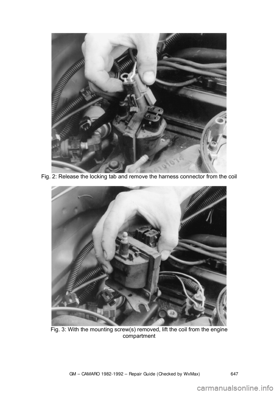
3. Disconnect the harness connecto r from the ignition coil.
4. Remove the coil mounting screws and the ignition coil. If necessary, drill
out and remove the rivets holding the coil to the bracket.
To install: 5. Place the ignition coil in position on the mounting bracket and install the
mounting screws.
6. Reconnect the harness connectors to the ignition coil. Confirm that the
harness connectors are firmly attached to the coil.
7. Install the secondary coil wire to the coil tower.
8. Connect the negative battery cable.
Page 646 of 875
GM – CAMARO 1982-1992 – Repair Guide (Checked by WxMax) 646
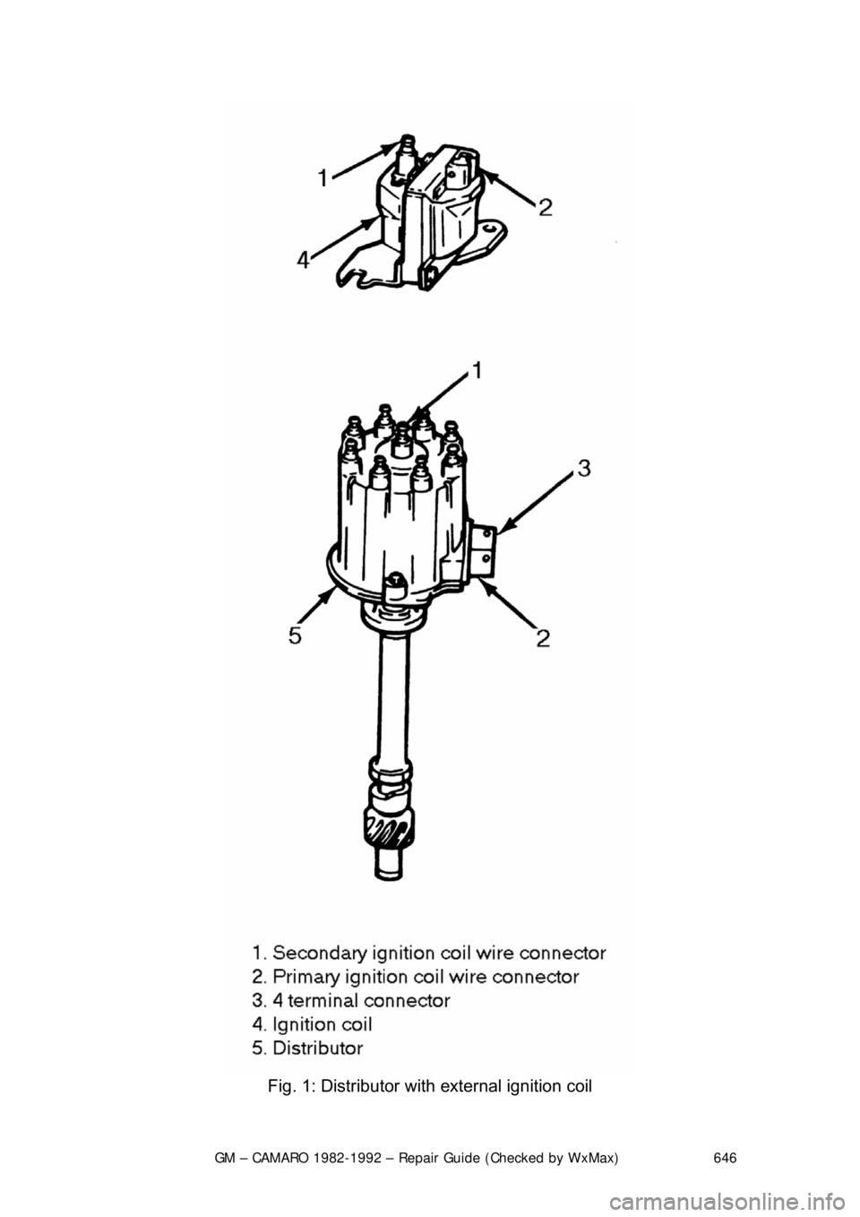
Fig. 1: Distributor with external ignition coil
Page 647 of 875
GM – CAMARO 1982-1992 – Repair Guide (Checked by WxMax) 647
Fig. 2: Release the locking tab and remo ve the harness connector from the coil
Fig. 3: With the mounting screw(s) re moved, lift the coil from the engine
compartment
Page 648 of 875

GM – CAMARO 1982-1992 – Repair Guide (Checked by WxMax) 648
INTERNALLY MOUNTED
1. Disconnect the negative battery cable.
2. Remove the cover and wire retainer.
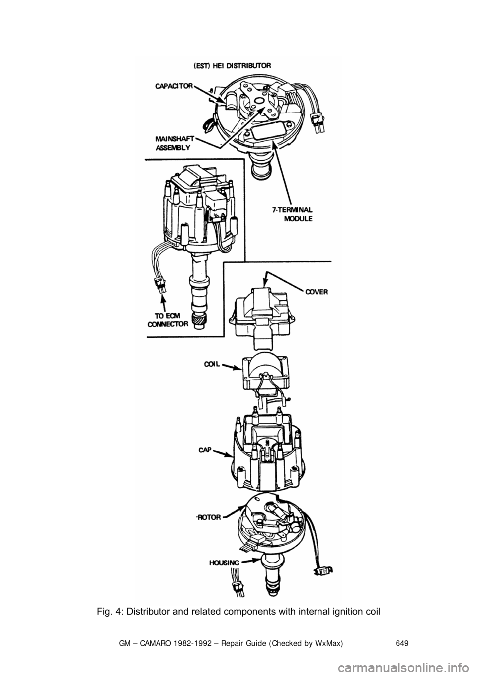
3. Disconnect the battery feed wire and coil connections from the cap.
4. Remove the coil cover attaching screws and cover.
5. Remove the coil attaching screws and lift the coil assembly from the
distributor cap.
To install: 6. Position the ignition coil and the leads into the cap. Be certain that the
resistor brush, ground lead and s eal are properly positioned.
7. Install the mounting screws.
8. Install the coil cove r and retainers. Reconnec t the feed wires and coil
connections to the cap.
9. Install the cover and wire retainer. Reconnect the negative battery cable.
Page 649 of 875
GM – CAMARO 1982-1992 – Repair Guide (Checked by WxMax) 649
Fig. 4: Distributor and related com ponents with internal ignition coil
Page 650 of 875
GM – CAMARO 1982-1992 – Repair Guide (Checked by WxMax) 650
DISTRIBUTOR CAP
1. If removing the ignition wires at the cap, take a moment to label the spark
plug wire positioning for each cylinder, at each tower. This will avoid
improper wire placement during assembly.
2. Disconnect the ignition switch wir e from the distributor cap. Also
disconnect the tachometer wire, if so equipped.
3. Release the coil connec tors from the cap.
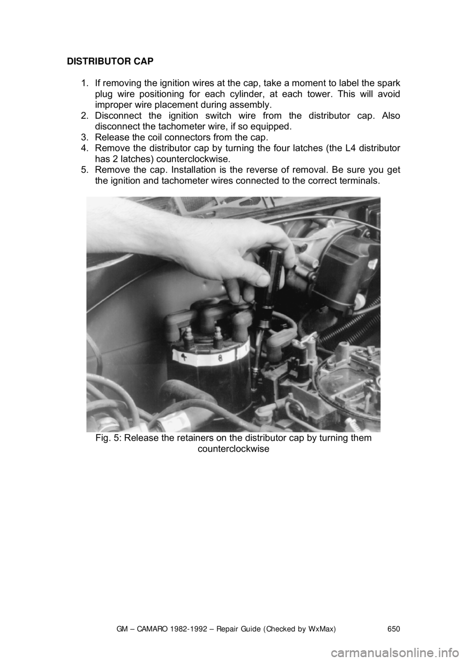
4. Remove the distributor cap by turn ing the four latches (the L4 distributor
has 2 latches) counterclockwise.
5. Remove the cap. Installation is the reverse of removal. Be sure you get
the ignition and tachometer wires c onnected to the correct terminals.
Fig. 5: Release the retainers on t he distributor cap by turning them
counterclockwise