CHEVROLET CAMARO 1982 Repair Guide
Manufacturer: CHEVROLET, Model Year: 1982, Model line: CAMARO, Model: CHEVROLET CAMARO 1982Pages: 875, PDF Size: 88.64 MB
Page 831 of 875
GM – CAMARO 1982-1992 – Repair Guide (Checked by WxMax) 831
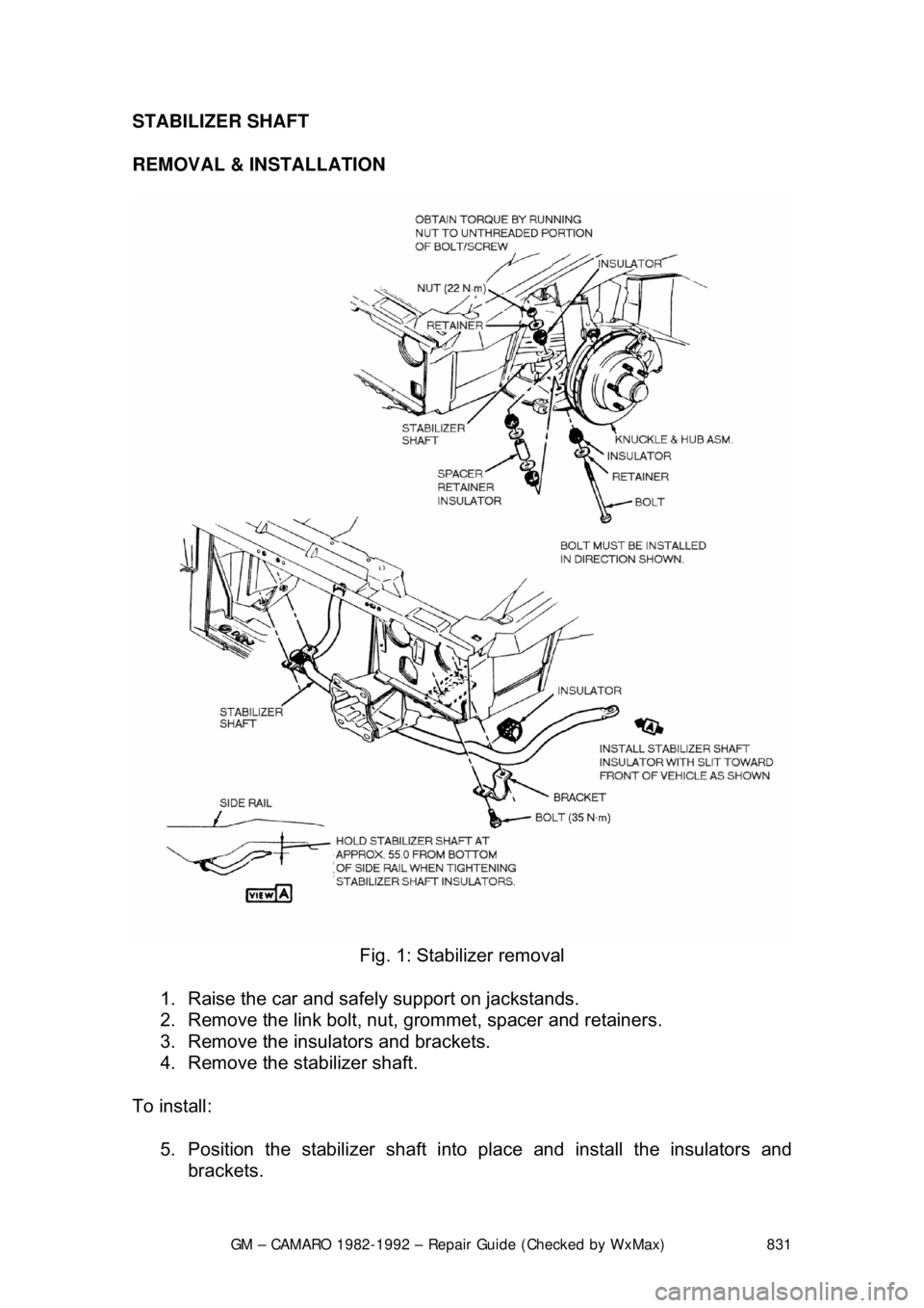
STABILIZER SHAFT
REMOVAL & INSTALLATION
Fig. 1: Stabilizer removal
1. Raise the car and safely support on jackstands.
2. Remove the link bolt, nut, grommet, spacer and retainers.
3. Remove the insulators and brackets.
4. Remove the stabilizer shaft.
To install: 5. Position the stabilizer shaft into place and install the insulators and
brackets.
Page 832 of 875
GM – CAMARO 1982-1992 – Repair Guide (Checked by WxMax) 832
6. Hold the stabilizer shaft approximat
ely 55mm from the bottom of the side
rail and torque the bracket bolts to 37 ft. lbs. (50 Nm).
7. Install the bolt, nut, grommets, spacer and retainers.
8. Lower the car.
LOWER CONTROL ARM
REMOVAL & INSTALLATION 1. Raise the car and safely support on jackstands.
2. Remove the wheel and tire.
3. Remove the stabilizer link and bush ings at the lower control arm.
4. Remove the pivot bolt nuts. DO NOT re move the pivot bolts at this time.
5. Install tool J-23028 or equivalent adapter to the jack and place into
position with tool J-23028 or equival ent adapter supporting bushings.
6. Install the jackstand under the outsi de frame rail on the opposite side of
the vehicle.
7. Raise tool J-23028 or equivalent adapter enough to remove both pivot
bolts.
8. Lower tool J-23028 or equivalent adapter.
9. Remove the spring and insulato r tape insulator to the spring.
10. Remove the ball joint from the knuckle.
11. To install, reverse the removal procedure.
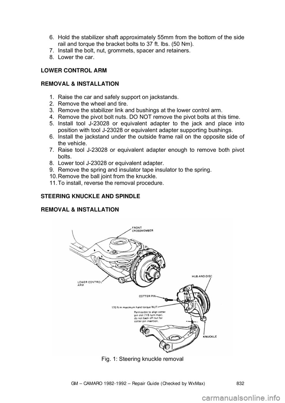
STEERING KNUCKLE AND SPINDLE
REMOVAL & INSTALLATION
Fig. 1: Steering knuckle removal
Page 833 of 875
GM – CAMARO 1982-1992 – Repair Guide (Checked by WxMax) 833
1. Siphon some brake fluid from the ma
ster cylinder. Raise and support the
vehicle.
2. Remove the wheel and tire. Remo ve the brake hose from the strut.
3. Remove the caliper and support on a wire. Refer to Brakes for
procedures, then remove the hub-and-disc.
4. Remove the splash shield. Disc onnect the tie rod from the steering
knuckle.
5. Support the lower control arm and disconnect the ball joint from the
steering knuckle using tool J-24292A.
6. Remove the 2 bolts securing the stru t to the steering knuckle and remove
the steering knuckle.
To install: 7. Place the steering knu ckle into position and install the 2 bolts securing
the strut to the st eering knuckle.
8. Support the lower control arm and c onnect the ball joint to the steering
knuckle.
9. Connect the tie rod to the steering knuckle. Install the splash shield.
10. Install the caliper.
11. Install the brake hose from the strut. Install the wheel and tire.
12. Lower the vehicle and refill the master cylinder with brake fluid.
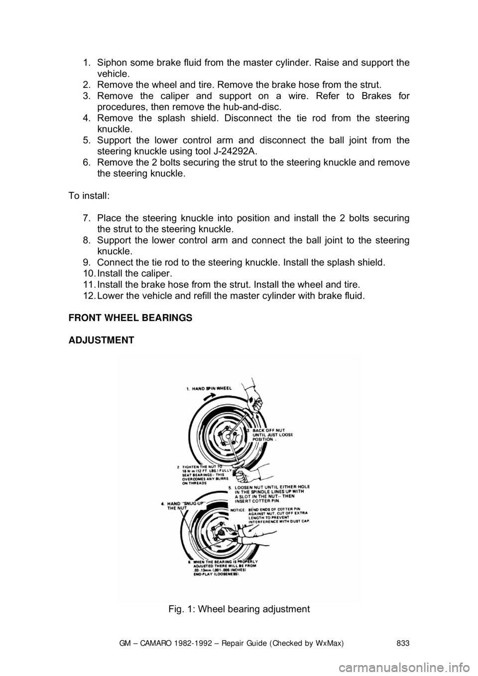
FRONT WHEEL BEARINGS
ADJUSTMENT
Fig. 1: Wheel bearing adjustment
Page 834 of 875

GM – CAMARO 1982-1992 – Repair Guide (Checked by WxMax) 834
1. Raise the car and support it at the lower arm.
2. Remove the hub dust cover and spindle cotter pin. Loosen the nut.
3. While spinning the wheel
, snug the nut down to seat the bearings. Do not
exert over 12 ft. lbs. (16 Nm) of force on the nut.
4. Back the nut off
1/4 turn or until it is just loos e. Line up the cotter pin hole
in the spindle with the hole in the nut.
5. Insert a new cotter pin. E ndplay should be between 0.001-0.005 in.
(0.03-0.13mm). If play exceeds this to lerance, the wheel bearings should
be replaced.
REMOVAL & INSTALLATION 1. Raise the car and support it at t he lower arm. Remove the wheel.
Remove the brake caliper and support it on a wire.
2. Remove the dust cap, cotter pin, ca stle nut, thrust washer and outside
wheel bearing. Pull the disc/hub assemb ly from the steering knuckle.
3. Pry out the inner seal and remove the inner bearing. If necessary to
remove the inner bearing races, use a hammer and a brass drift to drive
the bearing races from the hub.
4. Clean all parts in kerosene or e quivalent, DO NOT use gasoline. After
cleaning, check parts for excessive wear and replace damaged parts.
5. Smear grease inside of hub. Install the bearing races into hub, using a
hammer and a brass drift. Drive the ra ces in until they seat against the
shoulder of the hub.
6. Pack the bearings with grease and install the inner bearing in the hub.
Install a new grease seal, be careful not to damage the seal.
7. Install the disc/hub assembly onto t he steering knuckle. Install the outer
bearing, thrust washer and castle nut. Tighten the nut until the wheel
does not turn freely.
8. Back off the nut until the wheel tu rns freely and install the cotter pin.
Install the dust cap, caliper and wheel. Lower the car.
PACKING
Clean the wheel bearings thoroughly with solvent and check their condition
before installation.
CAUTION - Do not blow the beari ng dry with compressed ai r as this could allow
the bearing to turn without lubrication.
Apply a sizable amount of lubricant to the palm of one hand. Using your other
hand, work the bearing into the lubricant so that the grease is pushed through
the rollers and out the other side. Keep ro tating the bearing while continuing to
push the lubricant through it.
Page 835 of 875
GM – CAMARO 1982-1992 – Repair Guide (Checked by WxMax) 835
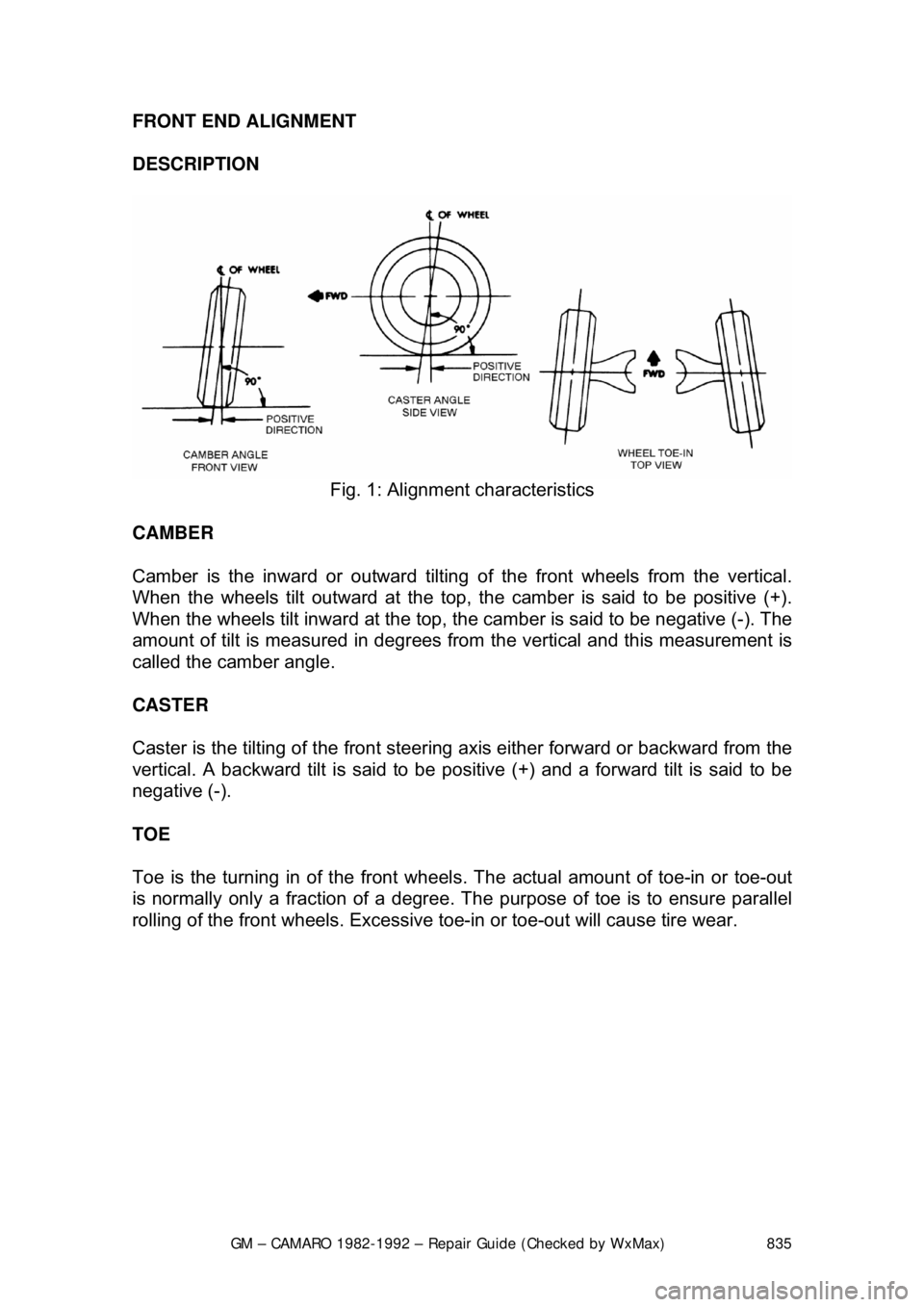
FRONT END ALIGNMENT
DESCRIPTION
Fig. 1: Alignment characteristics
CAMBER
Camber is the inward or outward tilting of the front wheels from the vertical.
When the wheels tilt outward at the top, the camber is said to be positive (+).
When the wheels tilt inward at the top, the camber is said to be negative (-). The
amount of tilt is measured in degrees from the vertical and this measurement is
called the camber angle.
CASTER
Caster is the tilting of the front steering axis either fo rward or backward from the
vertical. A backward tilt is said to be posit ive (+) and a forward tilt is said to be
negative (-).
TOE
Toe is the turning in of t he front wheels. The actual am ount of toe-in or toe-out
is normally only a fraction of a degree. T he purpose of toe is to ensure parallel
rolling of the front wheels. Excessive t oe-in or toe-out will cause tire wear.
Page 836 of 875
GM – CAMARO 1982-1992 – Repair Guide (Checked by WxMax) 836
ADJUSTMENT
CASTER/CAMBER
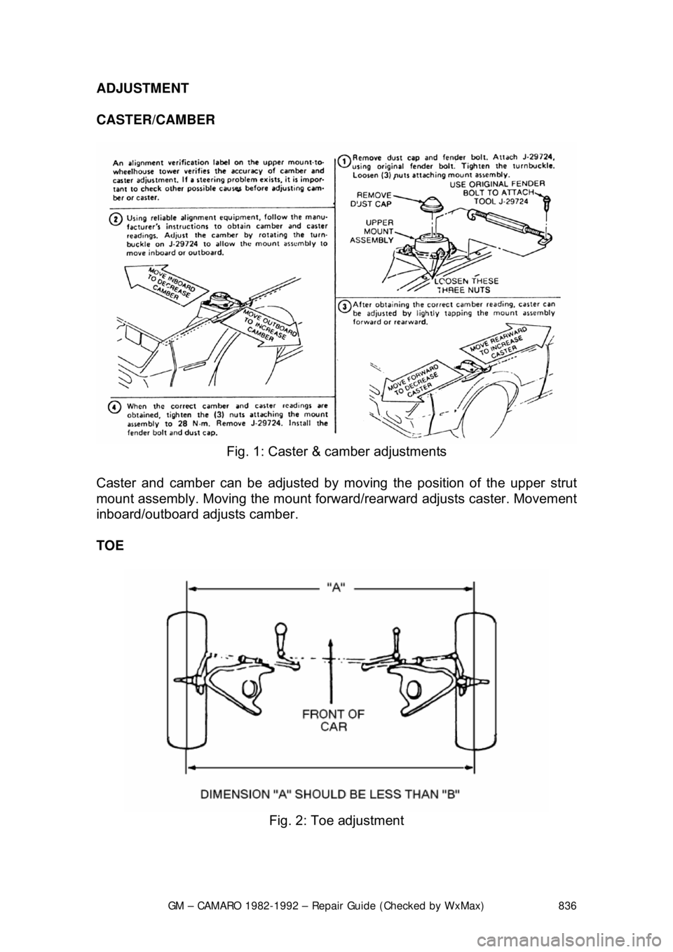
Fig. 1: Caster & camber adjustments
Caster and camber can be adjusted by moving the position of the upper strut
mount assembly. Moving the mount forwar d/rearward adjusts caster. Movement
inboard/outboard adjusts camber.
TOE
Fig. 2: Toe adjustment
Page 837 of 875

GM – CAMARO 1982-1992 – Repair Guide (Checked by WxMax) 837
1. Loosen the clamp bolts at each end
of the steering tie rod adjustable
sleeves.
2. With the steering wheel set strai ght ahead, turn the adjusting sleeves to
obtain the proper adjustment.
3. When the adjustment has been completed, check to see that the number
of threads showing on each end of the sleeve are equal. Also check that
tie rod end housings are at the right angles to the steering arm.
Page 838 of 875
GM – CAMARO 1982-1992 – Repair Guide (Checked by WxMax) 838
REAR SUSPENSION
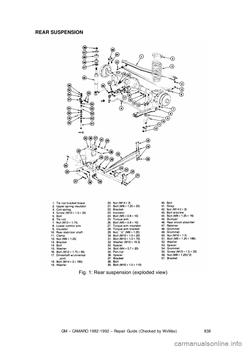
Fig. 1: Rear suspension (exploded view)
Page 839 of 875

GM – CAMARO 1982-1992 – Repair Guide (Checked by WxMax) 839
COIL SPRINGS
REMOVAL & INSTALLATION
1. Raise the car by the frame so that the rear axle can be independently
raised and lowered.
2. Support the rear axle with a floor jack.
3. If equipped with brake hose attaching brackets, disconnect the brackets
allowing the hoses to hang free. Do not disconnect the hoses. Perform
this step only if the hoses woul d otherwise be stretched and damaged
when the axle is lowered.
4. Disconnect the track bar from the axle.
5. Remove the lower shock absorber bol ts and lower the axle. Make sure
the axle is supported securely on t he floor jack and that there is no
chance of the axle slipping after the shock absorbers are disconnected.
On vehicles equipped with a 4-cylinder engine, remove the driveshaft.
6. Lower the axle and remove the coil spring. Do not lower the axle past th\
e limits of the brake lines or the lines will be damaged.
To install: 7. Position spring with the axle lowered.
8. On vehicles equipped with 4-cylinder engines, install the driveshaft.
9. Raise the axle and install the lower shock absorber bolts.
10. Connect the track bar to the axle.
11. Connect the brake hose attaching brackets, if removed.
12. Remove the support from the rear axle.
13. Lower the vehicle.
Page 840 of 875
GM – CAMARO 1982-1992 – Repair Guide (Checked by WxMax) 840
SHOCK ABSORBERS
REMOVAL & INSTALLATION
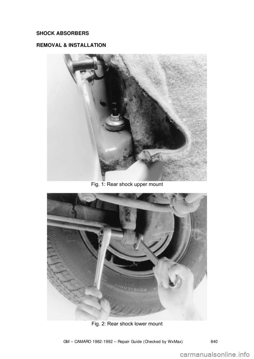
Fig. 1: Rear shock upper mount
Fig. 2: Rear shock lower mount