CHEVROLET CAMARO 1982 Repair Guide
Manufacturer: CHEVROLET, Model Year: 1982, Model line: CAMARO, Model: CHEVROLET CAMARO 1982Pages: 875, PDF Size: 88.64 MB
Page 811 of 875

GM – CAMARO 1982-1992 – Repair Guide (Checked by WxMax) 811
CAUTION
- NEVER hook the batteries up in a series circuit or the entire
electrical system will go up in smoke, including the starter!
Vehicles equipped with a diesel engine may utilize two 12 volt batteries. If so,
the batteries are connected in a parallel circuit (positive terminal to positive
terminal, negative terminal to negative te rminal). Hooking the batteries up in
parallel circuit increases battery cranki ng power without increasing total battery
voltage output. Output remains at 12 vo lts. On the other hand, hooking two 12
volt batteries up in a series circuit (positive terminal to negative terminal,
positive terminal to negative terminal) incr eases total battery output to 24 volts
(12 volts plus 12 volts).
JUMP STARTING PRECAUTIONS
• Be sure that both batteries are of t he same voltage. Vehicles covered by
this information and most vehicles on the road today utilize a 12 volt
charging system.
• Be sure that both batteries are of the same polarity (have the same
terminal, in most cases NEGATIVE grounded).
• Be sure that the vehicles are not touching or a short could occur.
• On serviceable batteries, be sure the v ent cap holes are not obstructed.
• Do not smoke or allow sparks anywhere near the batteries.
• In cold weather, make sure the battery electrolyte is not frozen. This can
occur more readily in a battery that has been in a state of discharge.
• Do not allow electrolyte to c ontact your skin or clothing.
JUMP STARTING PROCEDURE 1. Make sure that the voltages of the 2 batteries are the same. Most
batteries and charging systems are of the 12 volt variety.
2. Pull the jumping vehicle (with t he good battery) into a position so the
jumper cables can reach the dead battery and that vehicle's engine.
Make sure that the ve hicles do NOT touch.
3. Place the transmissions of both vehicles in Neutral (MT) or P (AT), as
applicable, then firmly set their parking brakes.
If necessary for safety reasons, the hazard lights on both vehicles may be
operated throughout the entir e procedure without significantly increasing the
difficulty of jumping the dead battery.
4. Turn all lights and accessories OFF on both vehicles. Make sure the ignition switches on both vehicles are turned to the OFF position.
5. Cover the battery cell caps with a rag, but do not cover the terminals.
6. Make sure the terminals on both batte ries are clean and free of corrosion
or proper electrical connection wil l be impeded. If necessary, clean the
battery terminals before proceeding.
7. Identify the positive (+) and negat ive (-) terminals on both batteries.
8. Connect the first jumper cable to the positive (+) terminal of the dead
battery, then connect the other end of that cable to the positive (+)
terminal of the booster (good) battery.
Page 812 of 875

GM – CAMARO 1982-1992 – Repair Guide (Checked by WxMax) 812
9. Connect one end of the other jumper
cable to the negative (-) terminal on
the booster battery and the final cable clamp to an engine bolt head,
alternator bracket or ot her solid, metallic point on the engine with the
dead battery. Try to pick a ground on the engine that is positioned away
from the battery in order to minimi ze the possibility of the 2 clamps
touching should one l oosen during the procedure. DO NOT connect this
clamp to the negative (-) term inal of the bad battery.
CAUTION - Be very careful to keep the jum per cables away from moving parts
(cooling fan, belts, etc.) on both engines.
10. Check to make sure that the c ables are routed away from any moving
parts, then start the d onor vehicle's engine. Run the engine at moderate
speed for several minutes to allow the dead battery a chance to receive
some initial charge.
11. With the donor vehicle's engine still r unning slightly above idle, try to start
the vehicle with the dead battery. Crank the engine for no more than 10 \
seconds at a time and let the starter cool for at least 20 seconds between
tries. If the vehicl e does not start in 3 tries, it is likely that something else
is also wrong or that the battery needs additional time to charge.
12. Once the vehicle is star ted, allow it to run at idle for a few seconds to
make sure that it is operating properly.
13. Turn ON the headlight s, heater blower and, if equipped, the rear
defroster of both vehicles in order to reduce the severity of voltage spikes
and subsequent risk of dam age to the vehicles' electrical systems when
the cables are disconnected. This st ep is especially important to any
vehicle equipped with computer control modules.
14. Carefully disconnect the cables in the reverse order of connection. Star\
t with the negative cable that is attached to the engine ground, then the
negative cable on the donor battery. Di sconnect the positive cable from
the donor battery and finally, disconnect the positive cable from the
formerly dead battery. Be careful when disconnecting the cables from the
positive terminals not to allow the alli gator clips to touch any metal on
either vehicle or a short and sparks will occur.
JACKING
Your vehicle was supplied with a jack for emergency road repairs. This jack is
fine for changing a flat tire or other s hort term procedures not requiring you to
go beneath the vehicle. If it is used in an emergency situation, carefully follow
the instructions provided eit her with the jack or in your owner's manual. Do not
attempt to use the jack on any portions of the vehicle other than specified by the
vehicle manufacturer. Always block the diagonally opposite wheel when using a
jack.
A more convenient way of jacking is the use of a garage or floor jack. You may
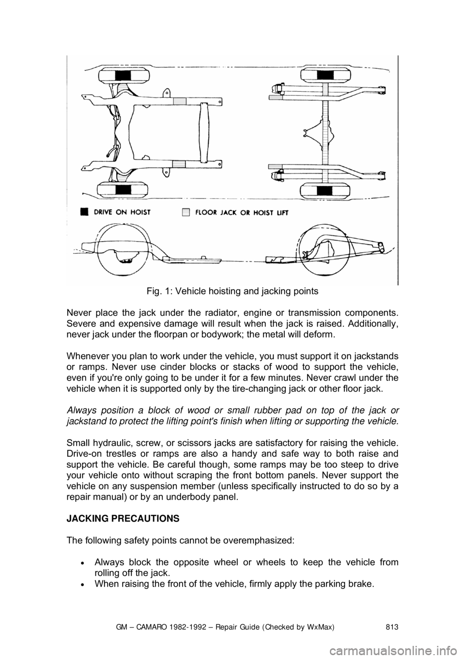
use the floor jack to raise the vehicle in the areas shown in the illustration .
Page 813 of 875
GM – CAMARO 1982-1992 – Repair Guide (Checked by WxMax) 813
Fig. 1: Vehicle hoisting and jacking points
Never place the jack under the radiator , engine or transmission components.
Severe and expensive damage wil l result when the jack is raised. Additionally,
never jack under the floorpan or body work; the metal will deform.
Whenever you plan to work under the v ehicle, you must support it on jackstands
or ramps. Never use cinder blocks or st acks of wood to support the vehicle,
even if you're only going to be under it for a few minutes. Never crawl under the
vehicle when it is supported only by the tire-changing jack or other floor jack.
Always position a block of wood or smal l rubber pad on top of the jack or
jackstand to protect the lifting point's finish when lifting or supporting the vehicle.
Small hydraulic, screw, or sci ssors jacks are satisfactory for raising the vehicle.
Drive-on trestles or ramps are also a handy and safe way to both raise and
support the vehicle. Be careful though, some ramps may be too steep to drive
your vehicle onto without scraping t he front bottom panels. Never support the
vehicle on any suspension member (unless specifically instructed to do so by a
repair manual) or by an underbody panel.
JACKING PRECAUTIONS
The following safety points cannot be overemphasized:
• Always block the opposite wheel or wheels to keep the vehicle from
rolling off the jack.
• When raising the front of the vehicle, firmly apply the parking brake.
Page 814 of 875
GM – CAMARO 1982-1992 – Repair Guide (Checked by WxMax) 814
•
When the drive wheels are to remain on the ground, leave the vehicle in
gear to help prevent it from rolling.
• Always use jackstands to support the vehicle when you are working
underneath. Place the stands beneath th e vehicle's jacking brackets.
Before climbing underneath, rock the vehicl e a bit to make sure it is firmly
supported.
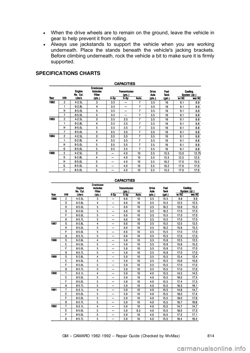
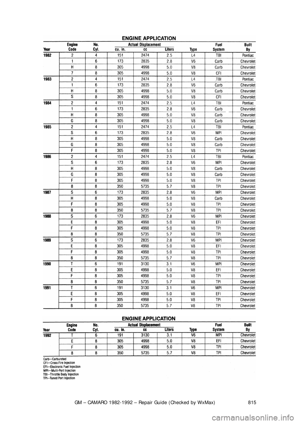
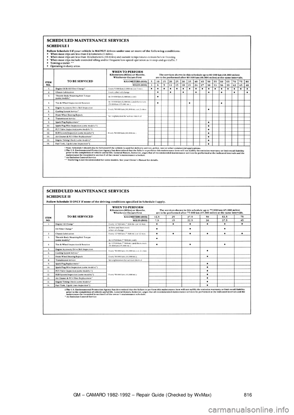
SPECIFICATIONS CHARTS
Page 815 of 875
GM – CAMARO 1982-1992 – Repair Guide (Checked by WxMax) 815
Page 816 of 875
GM – CAMARO 1982-1992 – Repair Guide (Checked by WxMax) 816
Page 817 of 875

GM – CAMARO 1982-1992 – Repair Guide (Checked by WxMax) 817
SUSPENSION & STEERING
SUSPENSION AND STEERING WHEELS
REMOVAL & INSTALLATION
• Park the vehicle on a level surface.
• Remove the jack, tire iron and, if nec essary, the spare tire from their
storage compartments.
• Check the owner's manual or refer to General Information & Maintenance
of this repair guide for the jacking poi nts on your vehicle. Then, place the
jack in the proper position.
• If equipped with lug nut trim caps, remo ve them by either unscrewing or
pulling them off the lug nuts, as appr opriate. Consult the owner's manual,
if necessary.
• If equipped with a wheel cover or hub c ap, insert the tapered end of the
tire iron in the groove and pry off the cover.
1. Apply the parking brake and block the diagonally opposite wheel with a
wheel chock or two.
Wheel chocks may be purchased at your lo cal auto parts store, or a block of
wood cut into wedges may be used. If possi ble, keep one or two of the chocks
in your tire storage compartment, in case any of the tires has to be removed on
the side of the road.
2. If equipped with an automatic transmi ssion, place the selector lever in P
or Park; with a manual transmission, place the shifter in Reverse.
3. With the tires still on the ground, use the tire iron/wrench to break the lug
nuts loose.
If a nut is stuck, never use heat to loosen it or damage to the wheel and
bearings may occur. If the nuts are seized, one or two heavy hammer blows
directly on the end of the bol t usually loosens the rust. Be careful, as continued
pounding will likely damage the brake drum or rotor.
3. Using the jack, raise the vehicle unt il the tire is clear of the ground.
Support the vehicle safely using jackstands.
4. Remove the lug nuts, then remove the tire and wheel assembly.
To install:
5. Make sure the wheel and hub mating su rfaces, as well as the wheel lug
studs, are clean and free of all foreign material. Always remove rust from
the wheel mounting surfac e and the brake rotor or drum. Failure to do so
may cause the lug nuts to loosen in service.
6. Install the tire and wheel asse mbly and hand-tighten the lug nuts.
7. Using the tire wrench, tighten all the lug nuts, in a crisscross pattern, until
they are snug.
8. Raise the vehicle and withdraw the jackstand, then lower the vehicle.
Page 818 of 875
GM – CAMARO 1982-1992 – Repair Guide (Checked by WxMax) 818
•
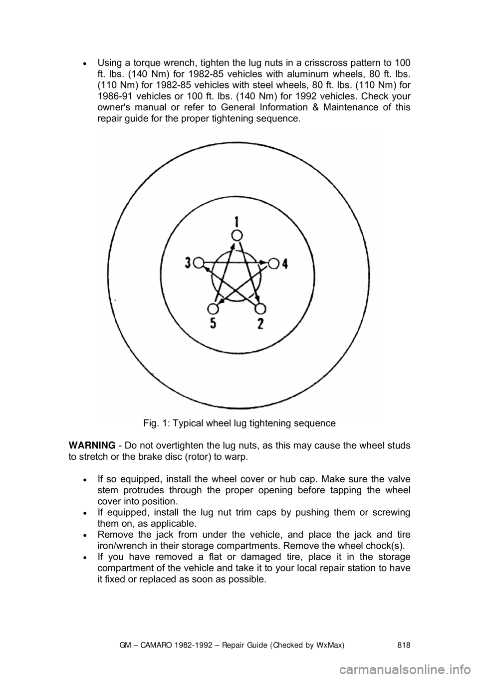
Using a torque wrench, tighten the lug nuts in a crisscross pattern to 100
ft. lbs. (140 Nm) for 1982-85 vehicles with aluminum wheels, 80 ft. lbs.
(110 Nm) for 1982-85 vehicles with st eel wheels, 80 ft. lbs. (110 Nm) for
1986-91 vehicles or 100 ft. lbs. (140 Nm) for 1992 vehicles. Check your
owner's manual or refer to General Information & Maintenance of this
repair guide for the proper tightening sequence.
Fig. 1: Typical wheel lug tightening sequence
WARNING - Do not overtighten the lug nuts, as this may cause the wheel studs
to stretch or the brake disc (rotor) to warp.
• If so equipped, install the wheel cover or hub cap. Make sure the valve
stem protrudes throu gh the proper opening bef ore tapping the wheel
cover into position.
• If equipped, install the lug nut trim caps by pushing them or screwing
them on, as applicable.
• Remove the jack from under the v ehicle, and place the jack and tire
iron/wrench in their storage compartment s. Remove the wheel chock(s).
• If you have removed a flat or damaged tire, place it in the storage
compartment of the vehicle and take it to your local repair station to have
it fixed or replaced as soon as possible.
Page 819 of 875
GM – CAMARO 1982-1992 – Repair Guide (Checked by WxMax) 819
INSPECTION
Inspect the tires for lacerations, puncture
marks, nails and other sharp objects.
Repair or replace as necessary. Also check the tires for treadwear and air
pressure as outlined in General Information & Maintenance of this repair guide.
Check the wheel assemblies for dents, crac ks, rust and metal fatigue. Repair or
replace as necessary.
WHEEL LUG STUDS
REMOVAL & INSTALLATION
WITH DISC BRAKES
1. Raise and support the appropriate end of the vehicle safely using
jackstands, then remove the wheel.
2. Remove the brake pads and caliper. Support the caliper aside using wire
or a coat hanger. For details, please re fer to Brakes of this repair guide.
3. Remove the outer w heel bearing and lift off the rotor. For details on
wheel bearing removal, installation and adjustment, please refer to
General Information & Maintenan ce of this repair guide.
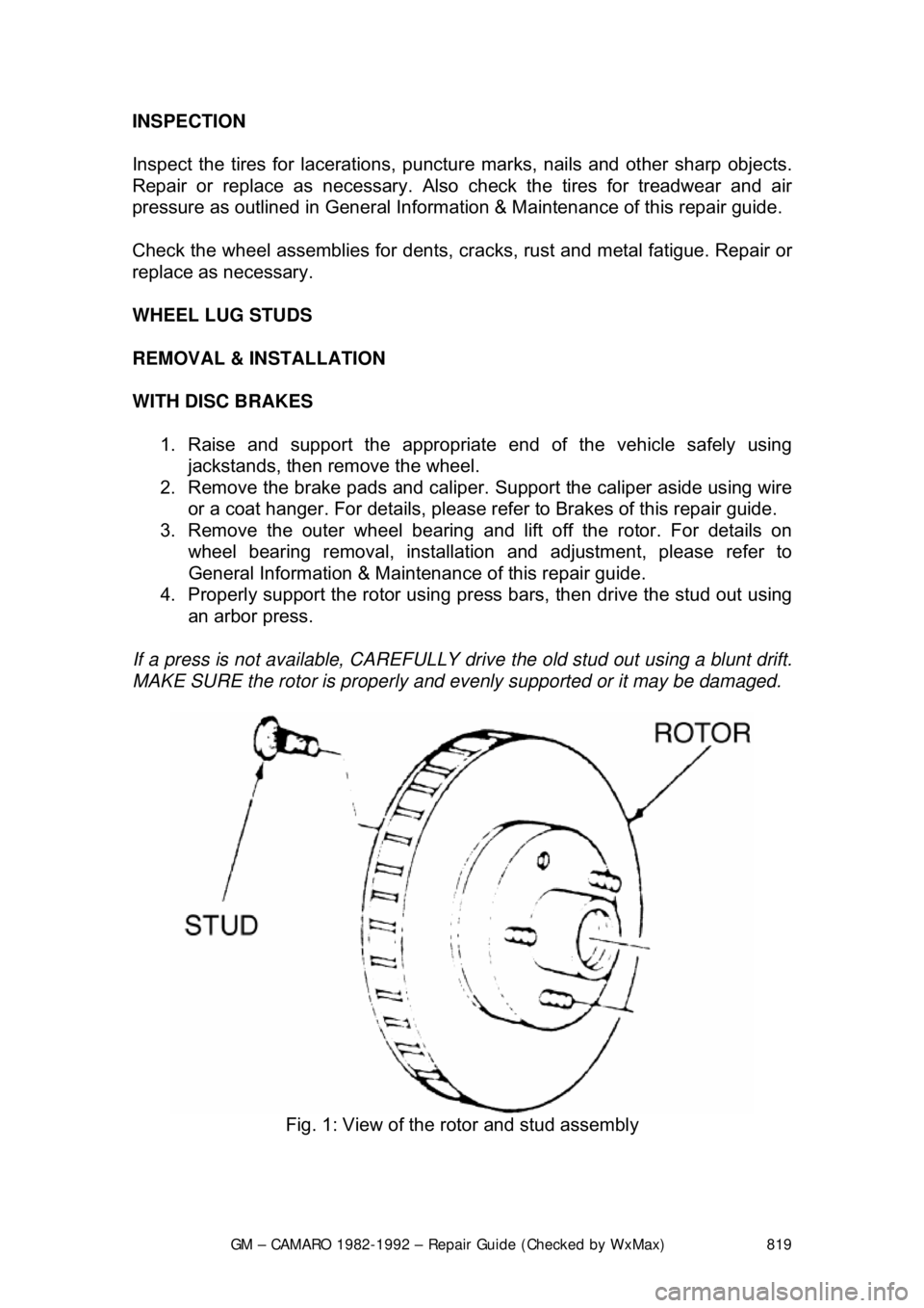
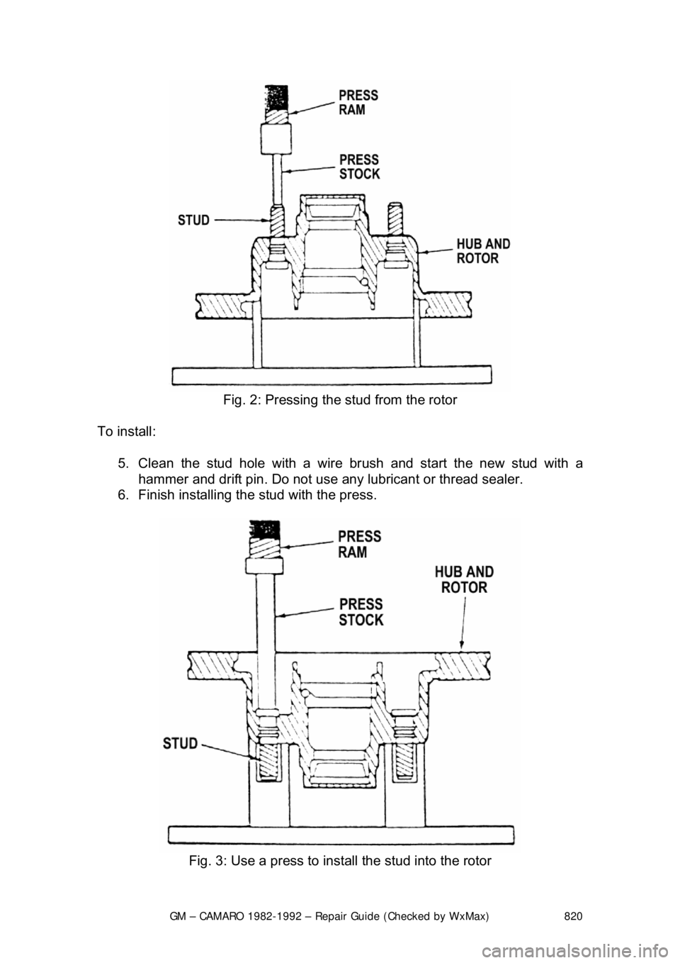
4. Properly support the rotor using pre ss bars, then drive the stud out using
an arbor press.
If a press is not available, CAREFULLY drive the old stud out using a blunt drift.
MAKE SURE the rotor is properly and ev enly supported or it may be damaged.
Fig. 1: View of the rotor and stud assembly
Page 820 of 875
GM – CAMARO 1982-1992 – Repair Guide (Checked by WxMax) 820
Fig. 2: Pressing the stud from the rotor
To install: 5. Clean the stud hole with a wire br ush and start the new stud with a
hammer and drift pin. Do not use any lubricant or thread sealer.
6. Finish installing t he stud with the press.
Fig. 3: Use a press to install the stud into the rotor