CHEVROLET PLYMOUTH ACCLAIM 1993 Service Manual
PLYMOUTH ACCLAIM 1993
CHEVROLET
CHEVROLET
https://www.carmanualsonline.info/img/24/56861/w960_56861-0.png
CHEVROLET PLYMOUTH ACCLAIM 1993 Service Manual
Trending: trunk, horn, ABS, dead battery, oil, automatic transmission, wheel bolt torque
Page 1971 of 2438
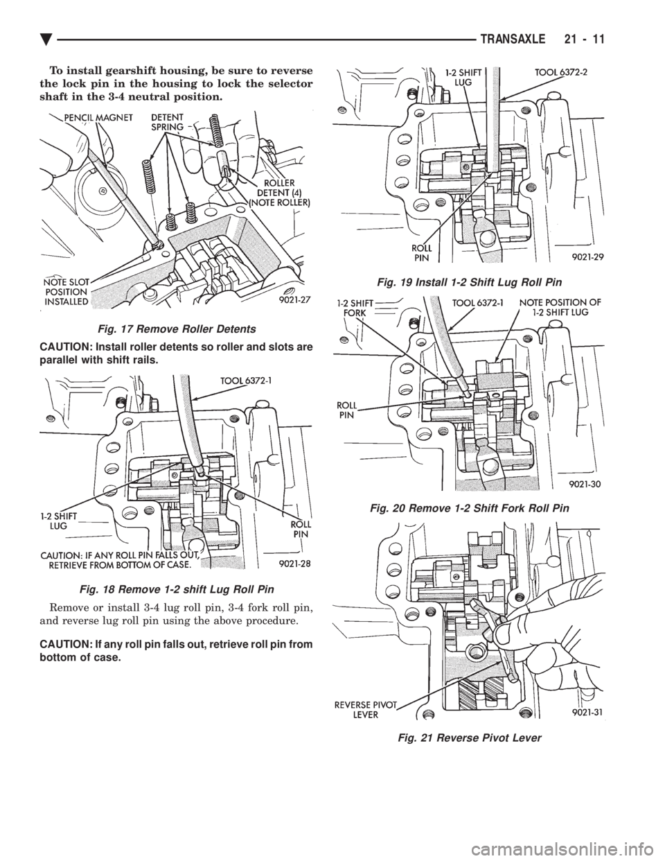
To install gearshift housing, be sure to reverse
the lock pin in the housing to lock the selector
shaft in the 3-4 neutral position.
CAUTION: Install roller detents so roller and slots are
parallel with shift rails.
Remove or install 3-4 lug roll pin, 3-4 fork roll pin,
and reverse lug roll pin using the above procedure.
CAUTION: If any roll pin falls out, retrieve roll pin from
bottom of case.
Fig. 19 Install 1-2 Shift Lug Roll Pin
Fig. 20 Remove 1-2 Shift Fork Roll Pin
Fig. 21 Reverse Pivot Lever
Fig. 17 Remove Roller Detents
Fig. 18 Remove 1-2 shift Lug Roll Pin
Ä TRANSAXLE 21 - 11
Page 1972 of 2438
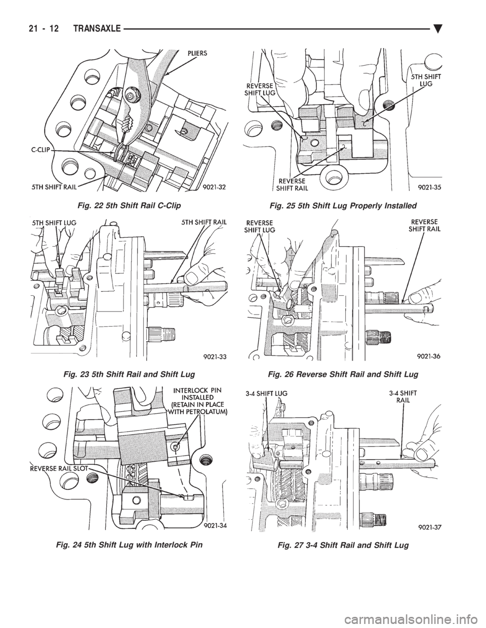
Fig. 22 5th Shift Rail C-Clip
Fig. 23 5th Shift Rail and Shift Lug
Fig. 24 5th Shift Lug with Interlock Pin
Fig. 25 5th Shift Lug Properly Installed
Fig. 26 Reverse Shift Rail and Shift Lug
Fig. 27 3-4 Shift Rail and Shift Lug
21 - 12 TRANSAXLE Ä
Page 1973 of 2438
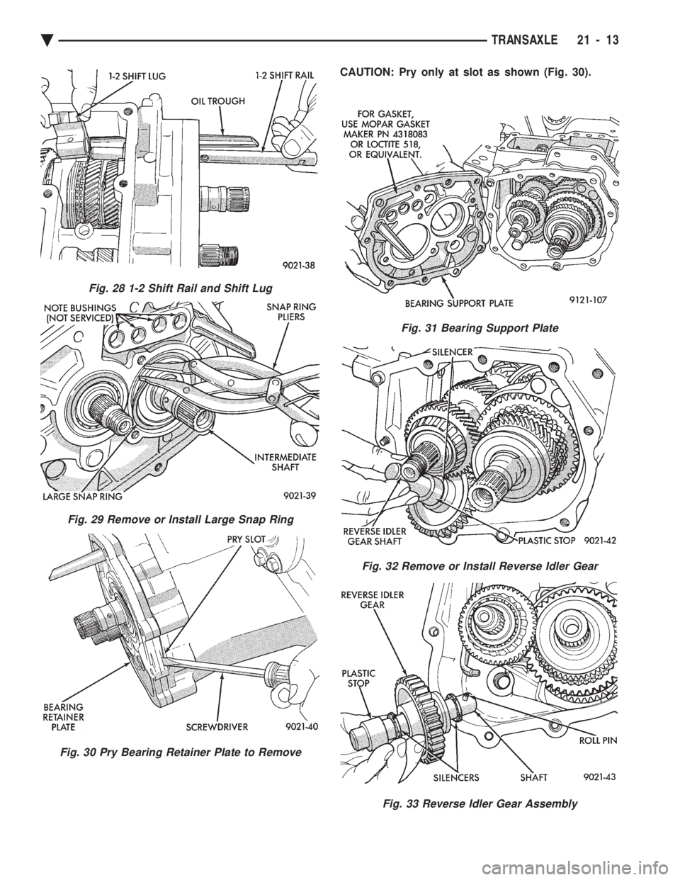
CAUTION: Pry only at slot as shown (Fig. 30).
Fig. 28 1-2 Shift Rail and Shift Lug
Fig. 29 Remove or Install Large Snap Ring
Fig. 30 Pry Bearing Retainer Plate to Remove
Fig. 31 Bearing Support Plate
Fig. 32 Remove or Install Reverse Idler Gear
Fig. 33 Reverse Idler Gear Assembly
Ä TRANSAXLE 21 - 13
Page 1974 of 2438
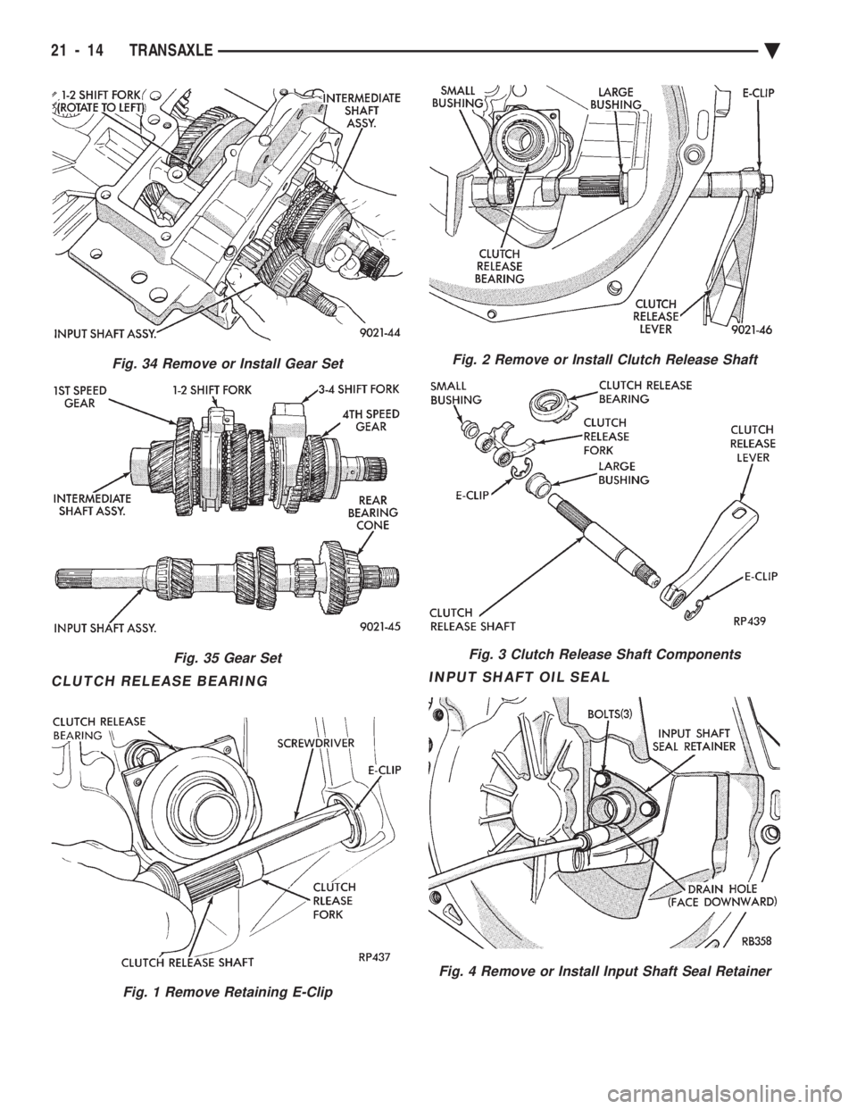
CLUTCH RELEASE BEARING INPUT SHAFT OIL SEAL
Fig. 34 Remove or Install Gear Set
Fig. 35 Gear Set
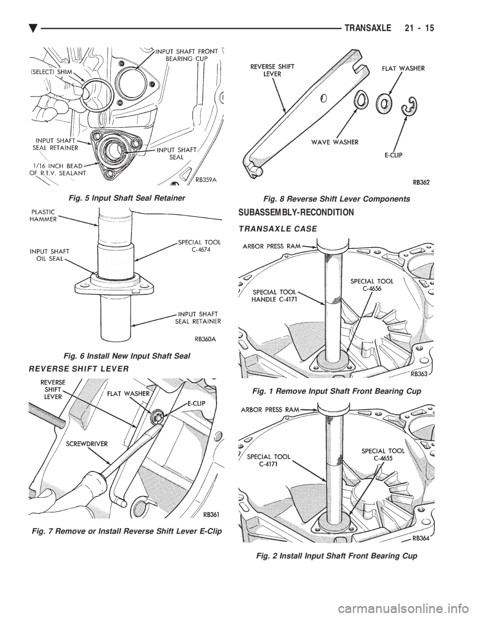
Fig. 1 Remove Retaining E-Clip
Fig. 2 Remove or Install Clutch Release Shaft
Fig. 3 Clutch Release Shaft Components
Fig. 4 Remove or Install Input Shaft Seal Retainer
21 - 14 TRANSAXLE
Ä
Page 1975 of 2438
REVERSE SHIFT LEVER
SUBASSEMBLY-RECONDITION
TRANSAXLE CASE
Fig. 6 Install New Input Shaft Seal
Fig. 7 Remove or Install Reverse Shift Lever E-Clip
Fig. 8 Reverse Shift Lever Components
Fig. 1 Remove Input Shaft Front Bearing Cup
Fig. 2 Install Input Shaft Front Bearing Cup
Fig. 5 Input Shaft Seal Retainer
Ä TRANSAXLE 21 - 15
Page 1976 of 2438
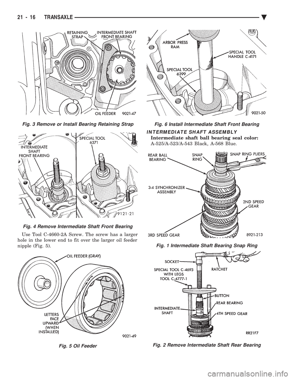
Use Tool C-4660-2A Screw. The screw has a larger
hole in the lower end to fit over the larger oil feeder
nipple (Fig. 5).
INTERMEDIATE SHAFT ASSEMBLY
Intermediate shaft ball bearing seal color:
A-525/A-523/A-543 Black, A-568 Blue.
Fig. 3 Remove or Install Bearing Retaining Strap
Fig. 4 Remove Intermediate Shaft Front Bearing
Fig. 5 Oil Feeder
Fig. 6 Install Intermediate Shaft Front Bearing
Fig. 1 Intermediate Shaft Bearing Snap Ring
Fig. 2 Remove Intermediate Shaft Rear Bearing
21 - 16 TRANSAXLE Ä
Page 1977 of 2438
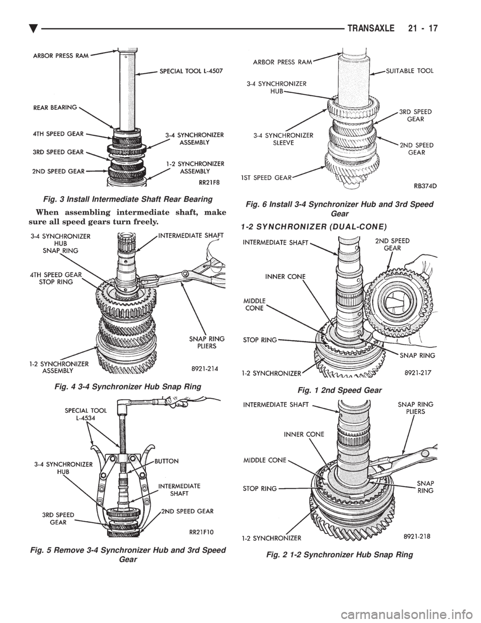
When assembling intermediate shaft, make
sure all speed gears turn freely.
1-2 SYNCHRONIZER (DUAL-CONE)
Fig. 6 Install 3-4 Synchronizer Hub and 3rd Speed Gear
Fig. 1 2nd Speed Gear
Fig. 2 1-2 Synchronizer Hub Snap Ring
Fig. 3 Install Intermediate Shaft Rear Bearing
Fig. 4 3-4 Synchronizer Hub Snap Ring
Fig. 5 Remove 3-4 Synchronizer Hub and 3rd Speed Gear
Ä TRANSAXLE 21 - 17
Page 1978 of 2438
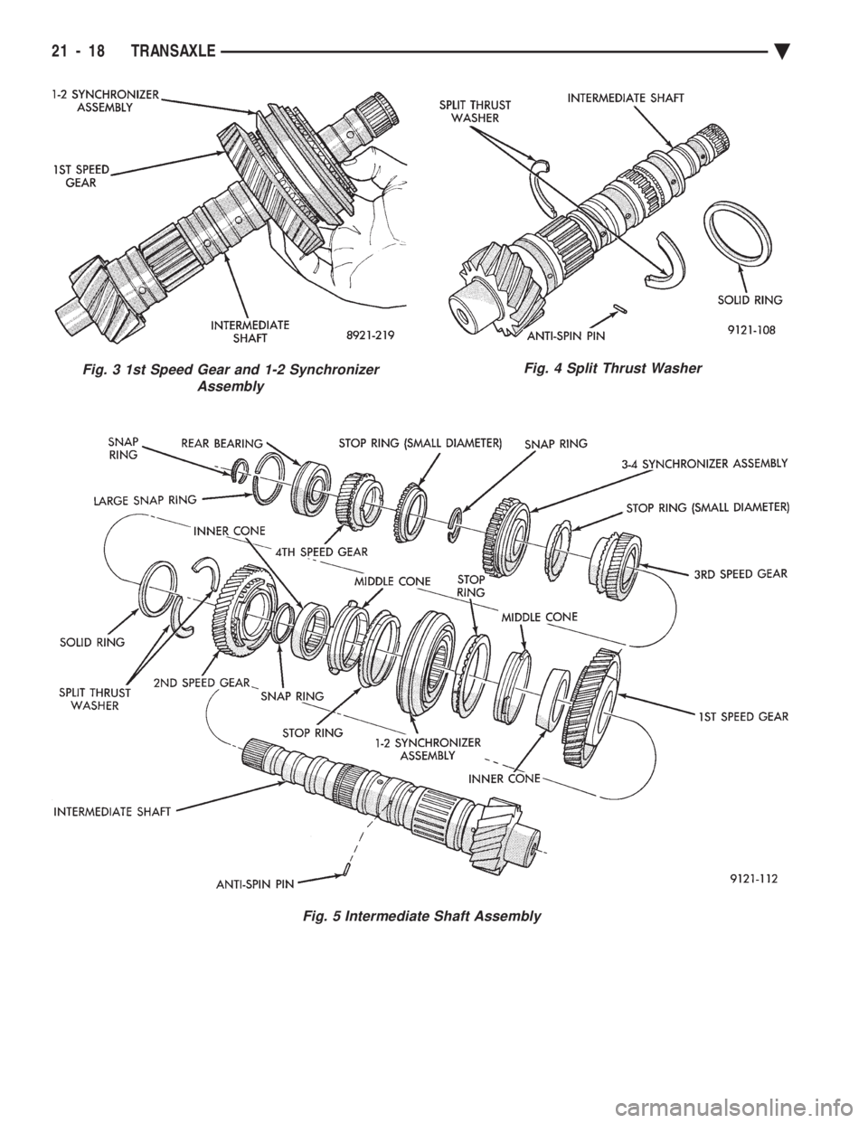
Fig. 3 1st Speed Gear and 1-2 Synchronizer AssemblyFig. 4 Split Thrust Washer
Fig. 5 Intermediate Shaft Assembly
21 - 18 TRANSAXLE Ä
Page 1979 of 2438
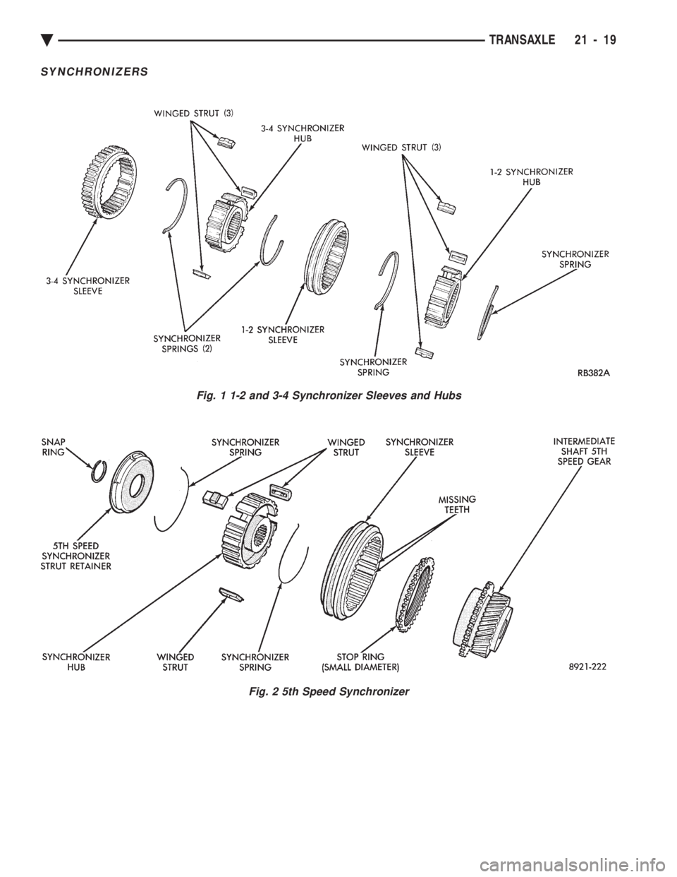
SYNCHRONIZERS
Fig. 1 1-2 and 3-4 Synchronizer Sleeves and Hubs
Fig. 2 5th Speed Synchronizer
Ä TRANSAXLE 21 - 19
Page 1980 of 2438
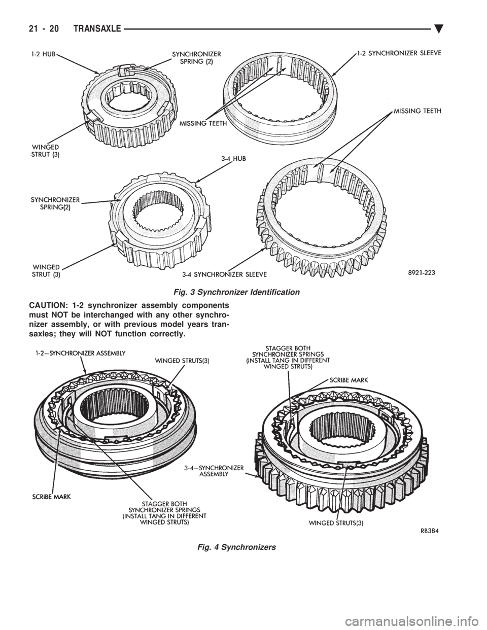
CAUTION: 1-2 synchronizer assembly components
must NOT be interchanged with any other synchro-
nizer assembly, or with previous model years tran-
saxles; they will NOT function correctly.
Fig. 3 Synchronizer Identification
Fig. 4 Synchronizers
21 - 20 TRANSAXLE Ä
Trending: horn, cooling, wheel bolts, parking brake, Solenoid, fuel fill door release, brake sensor
