CHEVROLET PLYMOUTH ACCLAIM 1993 Service Manual
Manufacturer: CHEVROLET, Model Year: 1993, Model line: PLYMOUTH ACCLAIM, Model: CHEVROLET PLYMOUTH ACCLAIM 1993Pages: 2438, PDF Size: 74.98 MB
Page 411 of 2438
GENERATOR INDEX
page page
General Information ........................ 9
Generator ReplacementÐ2.2L Turbo Engine (With 16 Valve Cylinder Head) ............. 10 Generator ReplacementÐ2.2L/2.5L Engine
...... 9
Generator ReplacementÐ3.0L Engine ......... 10
Generator ReplacementÐ3.3L/3.8L Engine ..... 11
GENERAL INFORMATION
This section will cover generator removal and instal-
lation only. Information covering generator on-vehicle
testing and diagnosis can be found in Group 8A,
Battery/Starting/Charging Systems Diagnostics. To
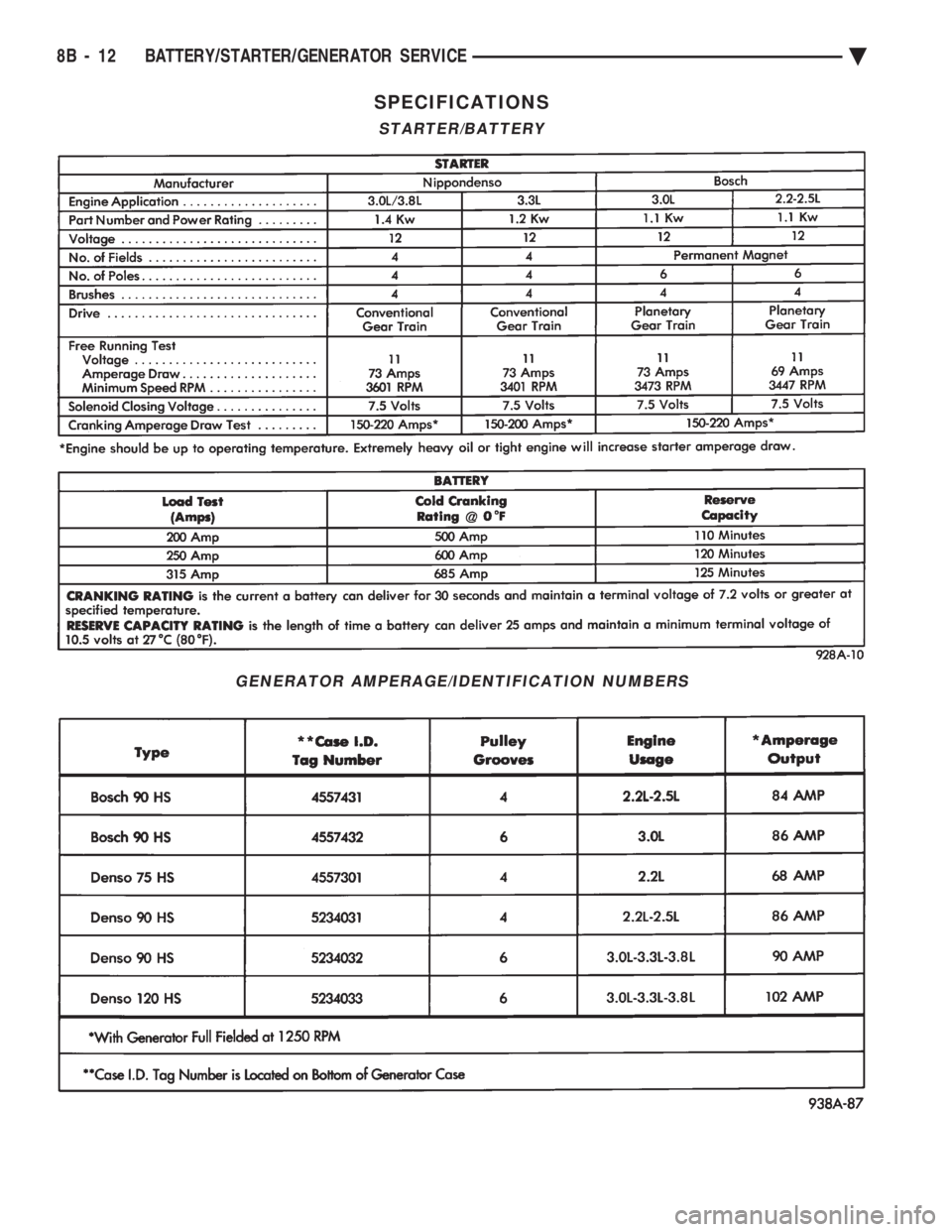
identify the generator, refer to the Generator Specifi-
cation chart at the rear of this section. These generators are not intended to be disas-
sembled for service. It must be replaced as an
assembly.
GENERATOR REPLACEMENTÐ2.2L/2.5L ENGINE
Removal and repositioning of A/C compressor (with-
out disconnecting refrigerant lines) is necessary on
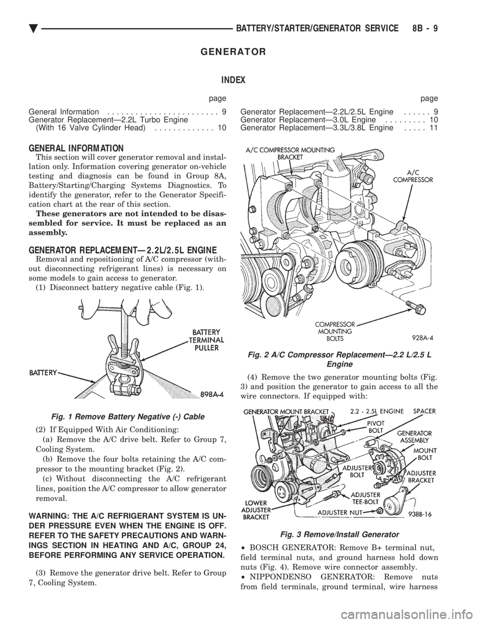
some models to gain access to generator. (1) Disconnect battery negative cable (Fig. 1).
(2) If Equipped With Air Conditioning:
(a) Remove the A/C drive belt. Refer to Group 7,
Cooling System. (b) Remove the four bolts retaining the A/C com-
pressor to the mounting bracket (Fig. 2). (c) Without disconnecting the A/C refrigerant
lines, position the A/C compressor to allow generator
removal.
WARNING: THE A/C REFRIGERANT SYSTEM IS UN-
DER PRESSURE EVEN WHEN THE ENGINE IS OFF.
REFER TO THE SAFETY PRECAUTIONS AND WARN-
INGS SECTION IN HEATING AND A/C, GROUP 24,
BEFORE PERFORMING ANY SERVICE OPERATION. (3) Remove the generator drive belt. Refer to Group
7, Cooling System. (4) Remove the two generator mounting bolts (Fig.
3) and position the generator to gain access to all the
wire connectors. If equipped with:
² BOSCH GENERATOR: Remove B+ terminal nut,
field terminal nuts, and ground harness hold down
nuts (Fig. 4). Remove wire connector assembly.
² NIPPONDENSO GENERATOR: Remove nuts
from field terminals, ground terminal, wire harness
Fig. 1 Remove Battery Negative (-) Cable
Fig. 2 A/C Compressor ReplacementÐ2.2 L/2.5 L Engine
Fig. 3 Remove/Install Generator
Ä BATTERY/STARTER/GENERATOR SERVICE 8B - 9
Page 412 of 2438
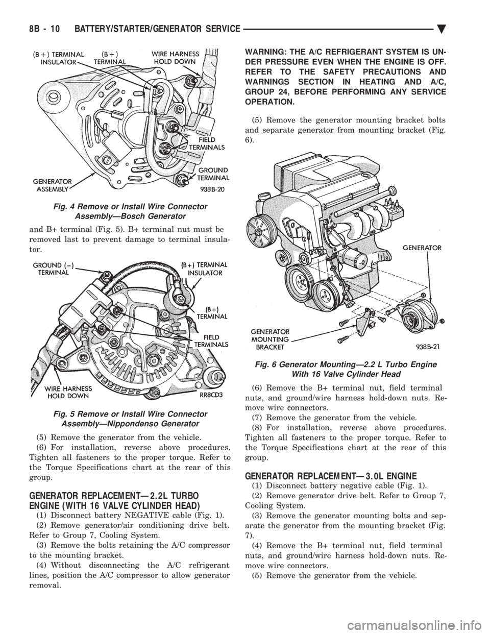
and B+ terminal (Fig. 5). B+ terminal nut must be
removed last to prevent damage to terminal insula-
tor. (5) Remove the generator from the vehicle.
(6) For installation, reverse above procedures.
Tighten all fasteners to the proper torque. Refer to
the Torque Specifications chart at the rear of this
group.
GENERATOR REPLACEMENTÐ2.2L TURBO
ENGINE (WITH 16 VALVE CYLINDER HEAD)
(1) Disconnect battery NEGATIVE cable (Fig. 1).
(2) Remove generator/air conditioning drive belt.
Refer to Group 7, Cooling System. (3) Remove the bolts retaining the A/C compressor
to the mounting bracket. (4) Without disconnecting the A/C refrigerant
lines, position the A/C compressor to allow generator
removal. WARNING: THE A/C REFRIGERANT SYSTEM IS UN-
DER PRESSURE EVEN WHEN THE ENGINE IS OFF.
REFER TO THE SAFETY PRECAUTIONS AND
WARNINGS SECTION IN HEATING AND A/C,
GROUP 24, BEFORE PERFORMING ANY SERVICE
OPERATION.
(5) Remove the generator mounting bracket bolts
and separate generator from mounting bracket (Fig.
6).
(6) Remove the B+ terminal nut, field terminal
nuts, and ground/wire harness hold-down nuts. Re-
move wire connectors. (7) Remove the generator from the vehicle.
(8) For installation, reverse above procedures.
Tighten all fasteners to the proper torque. Refer to
the Torque Specifications chart at the rear of this
group.
GENERATOR REPLACEMENTÐ3.0L ENGINE
(1) Disconnect battery negative cable (Fig. 1).
(2) Remove generator drive belt. Refer to Group 7,
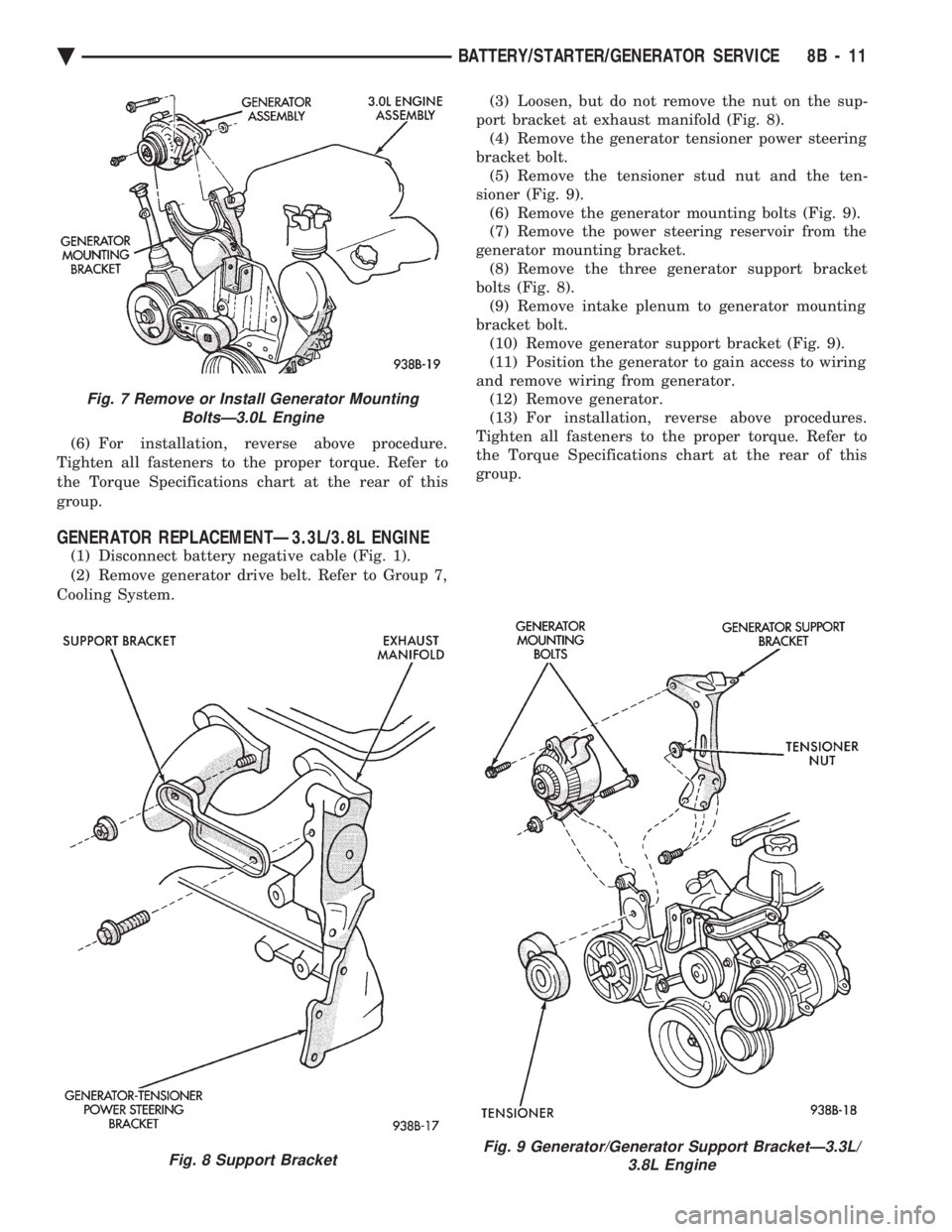
Cooling System. (3) Remove the generator mounting bolts and sep-
arate the generator from the mounting bracket (Fig.
7). (4) Remove the B+ terminal nut, field terminal
nuts, and ground/wire harness hold-down nuts. Re-
move wire connectors. (5) Remove the generator from the vehicle.
Fig. 4 Remove or Install Wire Connector AssemblyÐBosch Generator
Fig. 5 Remove or Install Wire ConnectorAssemblyÐNippondenso Generator
Fig. 6 Generator MountingÐ2.2 L Turbo Engine With 16 Valve Cylinder Head
8B - 10 BATTERY/STARTER/GENERATOR SERVICE Ä
Page 413 of 2438
(6) For installation, reverse above procedure.
Tighten all fasteners to the proper torque. Refer to
the Torque Specifications chart at the rear of this
group.
GENERATOR REPLACEMENTÐ3.3L/3.8L ENGINE
(1) Disconnect battery negative cable (Fig. 1).
(2) Remove generator drive belt. Refer to Group 7,
Cooling System. (3) Loosen, but do not remove the nut on the sup-
port bracket at exhaust manifold (Fig. 8). (4) Remove the generator tensioner power steering
bracket bolt. (5) Remove the tensioner stud nut and the ten-
sioner (Fig. 9). (6) Remove the generator mounting bolts (Fig. 9).
(7) Remove the power steering reservoir from the
generator mounting bracket. (8) Remove the three generator support bracket
bolts (Fig. 8). (9) Remove intake plenum to generator mounting
bracket bolt. (10) Remove generator support bracket (Fig. 9).
(11) Position the generator to gain access to wiring
and remove wiring from generator. (12) Remove generator.
(13) For installation, reverse above procedures.
Tighten all fasteners to the proper torque. Refer to
the Torque Specifications chart at the rear of this
group.
Fig. 7 Remove or Install Generator Mounting BoltsÐ3.0L Engine
Fig. 8 Support BracketFig. 9 Generator/Generator Support BracketÐ3.3L/ 3.8L Engine
Ä BATTERY/STARTER/GENERATOR SERVICE 8B - 11
Page 414 of 2438
SPECIFICATIONS
STARTER/BATTERY
GENERATOR AMPERAGE/IDENTIFICATION NUMBERS
8B - 12 BATTERY/STARTER/GENERATOR SERVICE Ä
Page 415 of 2438
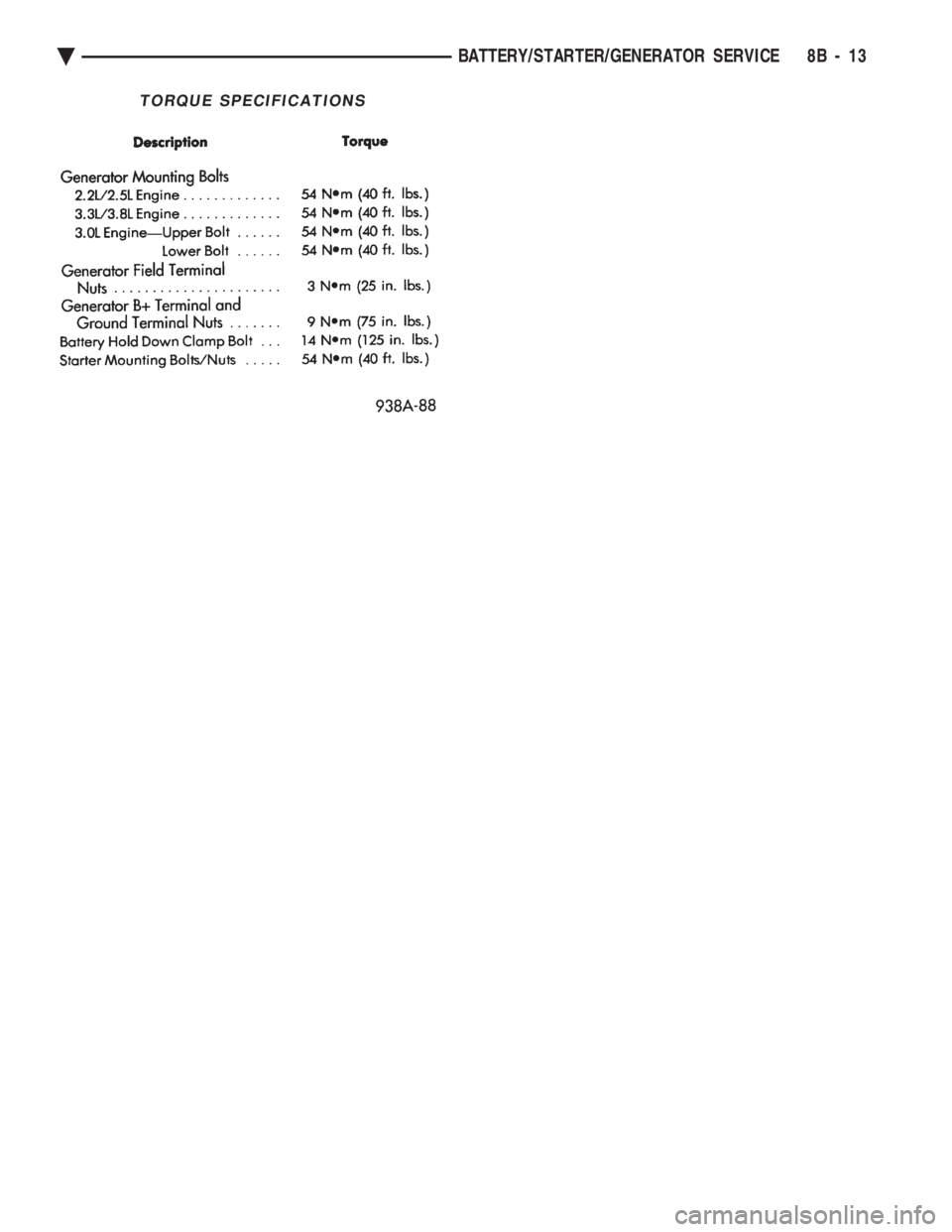
TORQUE SPECIFICATIONS
Ä BATTERY/STARTER/GENERATOR SERVICE 8B - 13
Page 416 of 2438

Page 417 of 2438
OVERHEAD CONSOLE
CONTENTS
page page
AA BODY .............................. 1
AC AND AY BODY ....................... 6 AG AND AJ BODIES
.................... 13
AP BODY ............................. 21
GENERAL INFORMATION AA BODY
INDEX
page page
Ambient Temperature Sensor ................ 6
Compass Calibration ....................... 2
Compass Diagnostics ...................... 5
Compass Module Replacement ............... 6
Demagnetizing Procedure ................... 4 Map Reading Lamps
....................... 1
Overhead Console Replacement .............. 5
Self-Diagnostic Test ....................... 5
Thermometer and Compass Operation ......... 1
Variance ................................ 2
MAP READING LAMPS
The map reading and rear passenger lamps are
turned on and off by pressing their individual switch
marked LAMP. These same lamps also serve as cour-
tesy lamps whenever a door is opened, the illumi-
nated entry system is activated, or the headlamp
switch is turned fully clockwise.
LAMP REPLACEMENT
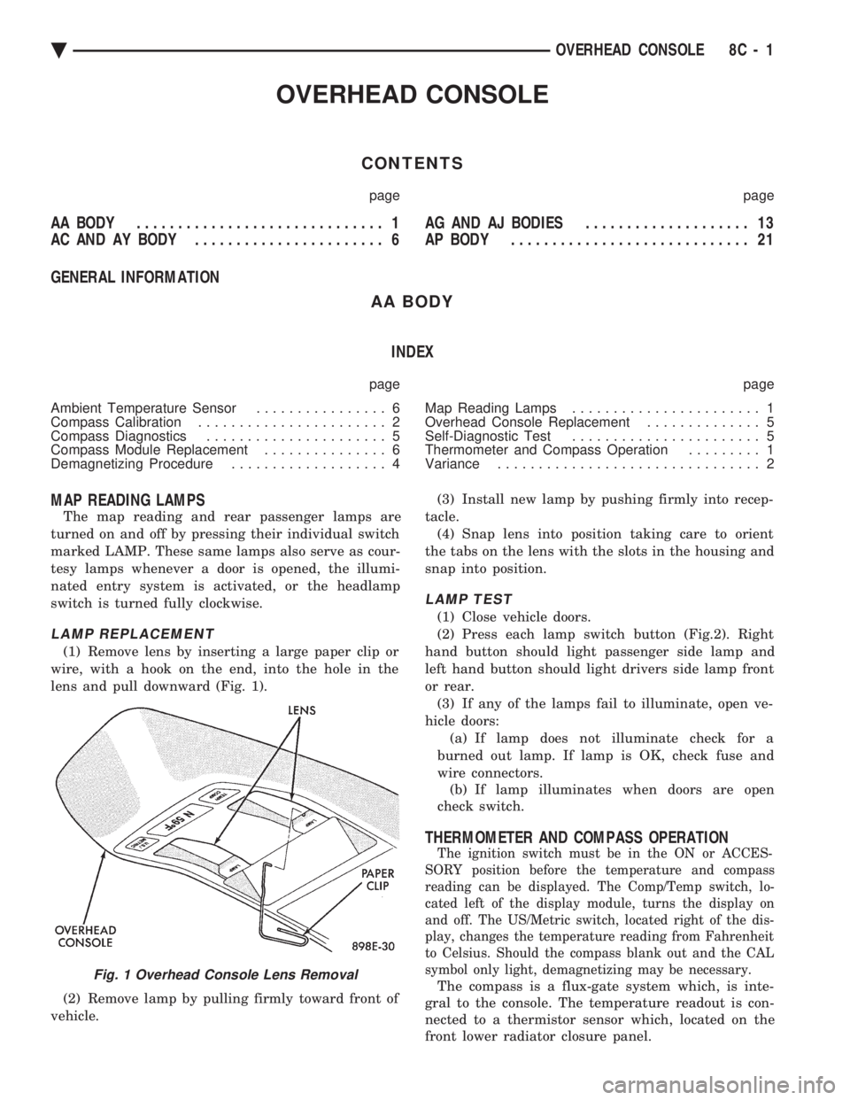
(1) Remove lens by inserting a large paper clip or
wire, with a hook on the end, into the hole in the
lens and pull downward (Fig. 1).
(2) Remove lamp by pulling firmly toward front of
vehicle. (3) Install new lamp by pushing firmly into recep-
tacle. (4) Snap lens into position taking care to orient
the tabs on the lens with the slots in the housing and
snap into position.
LAMP TEST
(1) Close vehicle doors.
(2) Press each lamp switch button (Fig.2). Right
hand button should light passenger side lamp and
left hand button should light drivers side lamp front
or rear. (3) If any of the lamps fail to illuminate, open ve-
hicle doors: (a) If lamp does not illuminate check for a
burned out lamp. If lamp is OK, check fuse and
wire connectors. (b) If lamp illuminates when doors are open
check switch.
THERMOMETER AND COMPASS OPERATION
The ignition switch must be in the ON or ACCES-
SORY position before the temperature and compass
reading can be displayed. The Comp/Temp switch, lo-
cated left of the display module, turns the display on
and off. The US/Metric switch, located right of the dis-
play, changes the temperature reading from Fahrenheit
to Celsius. Should the compass blank out and the CAL
symbol only light, demagnetizing may be necessary.
The compass is a flux-gate system which, is inte-
gral to the console. The temperature readout is con-
nected to a thermistor sensor which, located on the
front lower radiator closure panel.Fig. 1 Overhead Console Lens Removal
Ä OVERHEAD CONSOLE 8C - 1
Page 418 of 2438
When the vehicle is standing still, engine compart-
ment temperature may be radiated to the tempera-
ture sensor. Therefore the most accurate ambient
temperature readings are displayed when the vehicle
is moving in a forward motion. When the ignition switch is turned off the last dis-
played temperature reading stays in memory. When
the ignition switch is turned on again the thermom-
eter will display the memory temperature for 1
minute; then update the display to the actual tem-
perature within 5 minutes. Refer to Compass and
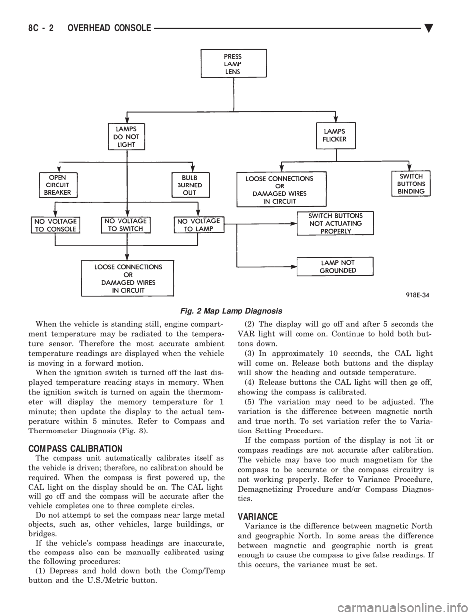
Thermometer Diagnosis (Fig. 3).
COMPASS CALIBRATION
The compass unit automatically calibrates itself as
the vehicle is driven; therefore, no calibration should be
required. When the compass is first powered up, the
CAL light on the display should be on. The CAL light
will go off and the compass will be accurate after the
vehicle completes one to three complete circles.
Do not attempt to set the compass near large metal
objects, such as, other vehicles, large buildings, or
bridges. If the vehicle's compass headings are inaccurate,
the compass also can be manually calibrated using
the following procedures: (1) Depress and hold down both the Comp/Temp
button and the U.S./Metric button. (2) The display will go off and after 5 seconds the
VAR light will come on. Continue to hold both but-
tons down. (3) In approximately 10 seconds, the CAL light
will come on. Release both buttons and the display
will show the heading and outside temperature. (4) Release buttons the CAL light will then go off,
showing the compass is calibrated. (5) The variation may need to be adjusted. The
variation is the difference between magnetic north
and true north. To set variation refer the to Varia-
tion Setting Procedure. If the compass portion of the display is not lit or
compass readings are not accurate after calibration.
The vehicle may have too much magnetism for the
compass to be accurate or the compass circuitry is
not working properly. Refer to Variance Procedure,
Demagnetizing Procedure and/or Compass Diagnos-
tics.VARIANCE
Variance is the difference between magnetic North
and geographic North. In some areas the difference
between magnetic and geographic north is great
enough to cause the compass to give false readings. If
this occurs, the variance must be set.
Fig. 2 Map Lamp Diagnosis
8C - 2 OVERHEAD CONSOLE Ä
Page 419 of 2438
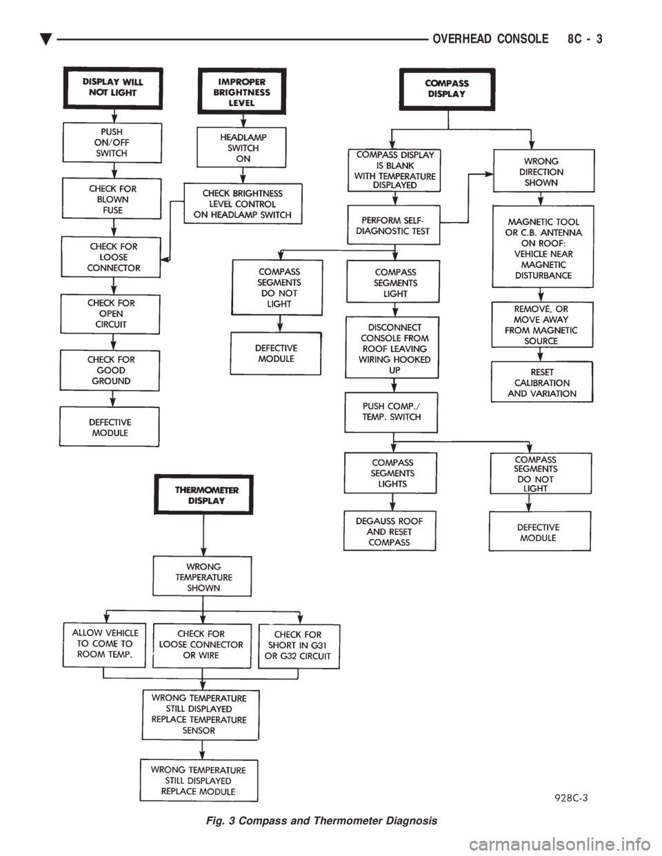
Fig. 3 Compass and Thermometer Diagnosis
Ä OVERHEAD CONSOLE 8C - 3
Page 420 of 2438
VARIANCE SETTING PROCEDURE
There are two methods for setting variance while
in variance set mode. If the CAL symbol is on proce-
dure 2 must be used.
PROCEDURE 1
(1) Turn ignition switch to the on position.
(2) Press and hold the Comp/Temp button till the
display is turned OFF. (3) While continuing to hold Comp/Temp button
depress and hold US/Metric button until the VAR
symbol lights in approximately 5 seconds. (4) Release buttons.
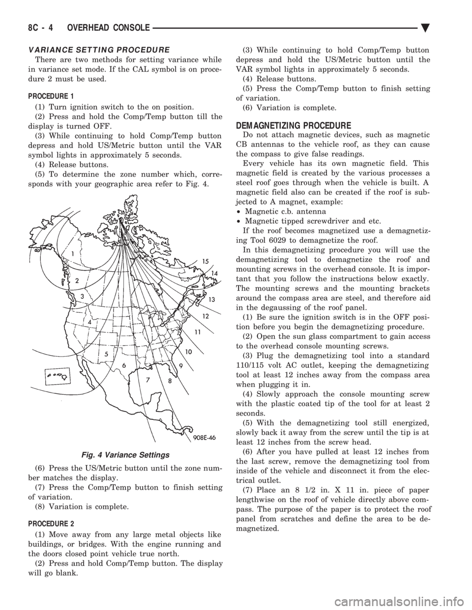
(5) To determine the zone number which, corre-
sponds with your geographic area refer to Fig. 4.
(6) Press the US/Metric button until the zone num-
ber matches the display. (7) Press the Comp/Temp button to finish setting
of variation. (8) Variation is complete.
PROCEDURE 2 (1) Move away from any large metal objects like
buildings, or bridges. With the engine running and
the doors closed point vehicle true north. (2) Press and hold Comp/Temp button. The display
will go blank. (3) While continuing to hold Comp/Temp button
depress and hold the US/Metric button until the
VAR symbol lights in approximately 5 seconds. (4) Release buttons.
(5) Press the Comp/Temp button to finish setting
of variation. (6) Variation is complete.
DEMAGNETIZING PROCEDURE
Do not attach magnetic devices, such as magnetic
CB antennas to the vehicle roof, as they can cause
the compass to give false readings. Every vehicle has its own magnetic field. This
magnetic field is created by the various processes a
steel roof goes through when the vehicle is built. A
magnetic field also can be created if the roof is sub-
jected to A magnet, example:
² Magnetic c.b. antenna
² Magnetic tipped screwdriver and etc.
If the roof becomes magnetized use a demagnetiz-
ing Tool 6029 to demagnetize the roof. In this demagnetizing procedure you will use the
demagnetizing tool to demagnetize the roof and
mounting screws in the overhead console. It is impor-
tant that you follow the instructions below exactly.
The mounting screws and the mounting brackets
around the compass area are steel, and therefore aid
in the degaussing of the roof panel. (1) Be sure the ignition switch is in the OFF posi-
tion before you begin the demagnetizing procedure. (2) Open the sun glass compartment to gain access
to the overhead console mounting screws. (3) Plug the demagnetizing tool into a standard
110/115 volt AC outlet, keeping the demagnetizing
tool at least 12 inches away from the compass area
when plugging it in. (4) Slowly approach the console mounting screw
with the plastic coated tip of the tool for at least 2
seconds. (5) With the demagnetizing tool still energized,
slowly back it away from the screw until the tip is at
least 12 inches from the screw head. (6) After you have pulled at least 12 inches from
the last screw, remove the demagnetizing tool from
inside of the vehicle and disconnect it from the elec-
trical outlet. (7) Place an 8 1/2 in. X 11 in. piece of paper
lengthwise on the roof of vehicle directly above com-
pass. The purpose of the paper is to protect the roof
panel from scratches and define the area to be de-
magnetized.
Fig. 4 Variance Settings
8C - 4 OVERHEAD CONSOLE Ä