CHEVROLET PLYMOUTH ACCLAIM 1993 Service Manual
Manufacturer: CHEVROLET, Model Year: 1993, Model line: PLYMOUTH ACCLAIM, Model: CHEVROLET PLYMOUTH ACCLAIM 1993Pages: 2438, PDF Size: 74.98 MB
Page 471 of 2438
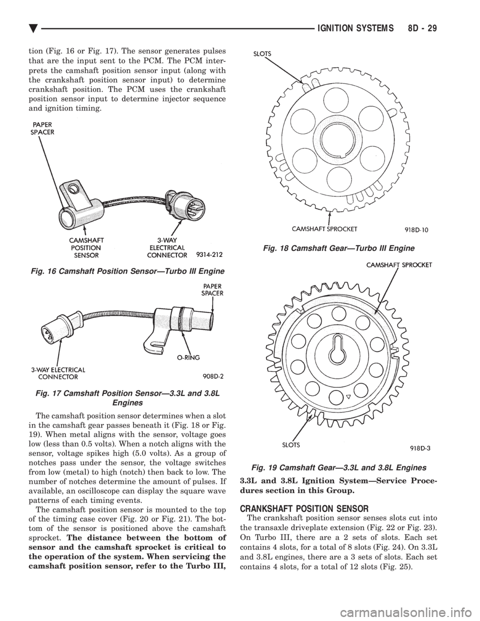
tion (Fig. 16 or Fig. 17). The sensor generates pulses
that are the input sent to the PCM. The PCM inter-
prets the camshaft position sensor input (along with
the crankshaft position sensor input) to determine
crankshaft position. The PCM uses the crankshaft
position sensor input to determine injector sequence
and ignition timing.
The camshaft position sensor determines when a slot
in the camshaft gear passes beneath it (Fig. 18 or Fig.
19). When metal aligns with the sensor, voltage goes
low (less than 0.5 volts). When a notch aligns with the
sensor, voltage spikes high (5.0 volts). As a group of
notches pass under the sensor, the voltage switches
from low (metal) to high (notch) then back to low. The
number of notches determine the amount of pulses. If
available, an oscilloscope can display the square wave
patterns of each timing events. The camshaft position sensor is mounted to the top
of the timing case cover (Fig. 20 or Fig. 21). The bot-
tom of the sensor is positioned above the camshaft
sprocket. The distance between the bottom of
sensor and the camshaft sprocket is critical to
the operation of the system. When servicing the
camshaft position sensor, refer to the Turbo III, 3.3L and 3.8L Ignition SystemÐService Proce-
dures section in this Group.
CRANKSHAFT POSITION SENSOR
The crankshaft position sensor senses slots cut into
the transaxle driveplate extension (Fig. 22 or Fig. 23).
On Turbo III, there ar e a 2 sets of slots. Each set
contains 4 slots, for a total of 8 slots (Fig. 24). On 3.3L
and 3.8L engines, there ar e a 3 sets of slots. Each set
contains 4 slots, for a total of 12 slots (Fig. 25).
Fig. 16 Camshaft Position SensorÐTurbo III Engine
Fig. 17 Camshaft Position SensorÐ3.3L and 3.8L Engines
Fig. 18 Camshaft GearÐTurbo III Engine
Fig. 19 Camshaft GearÐ3.3L and 3.8L Engines
Ä IGNITION SYSTEMS 8D - 29
Page 472 of 2438
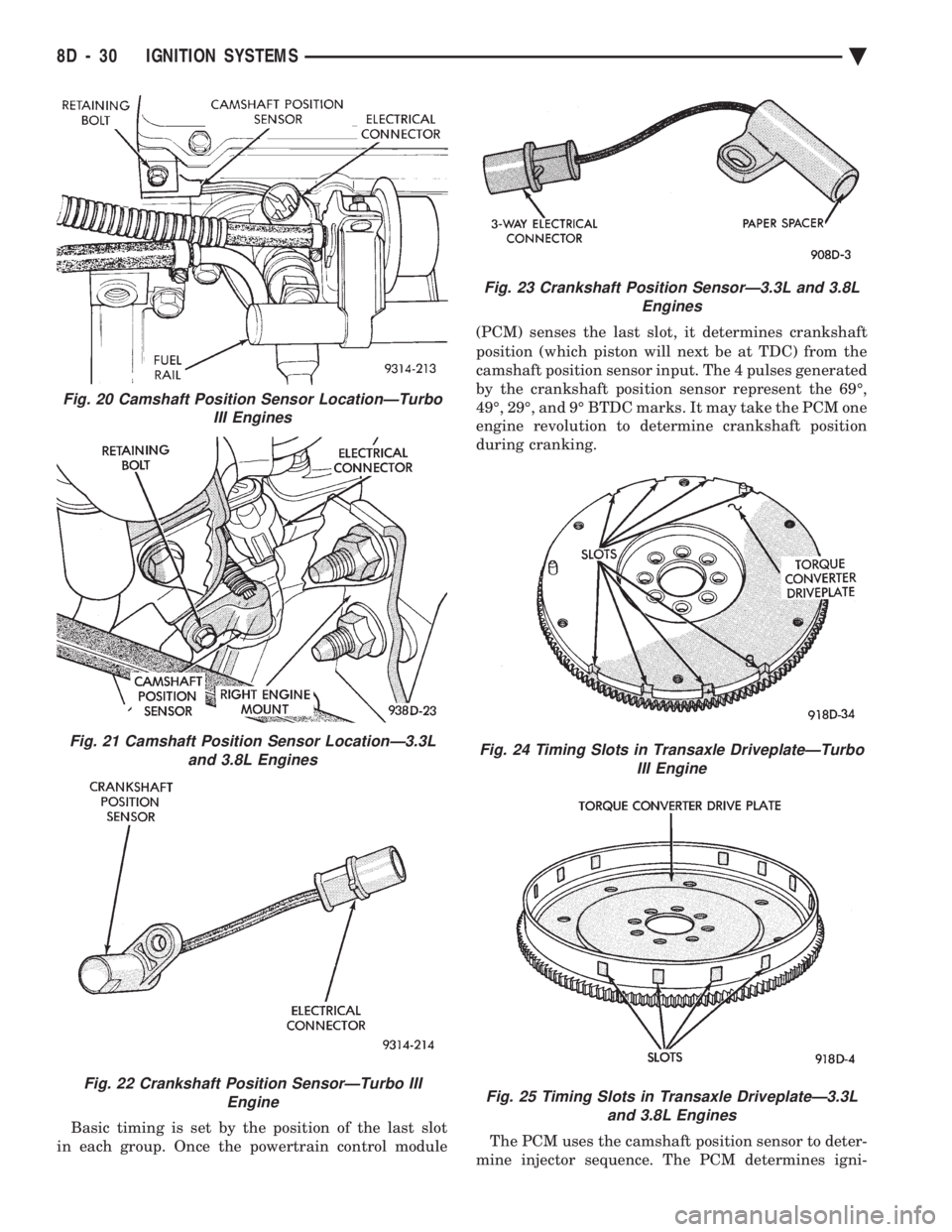
Basic timing is set by the position of the last slot
in each group. Once the powertrain control module (PCM) senses the last slot, it determines crankshaft
position (which piston will next be at TDC) from the
camshaft position sensor input. The 4 pulses generated
by the crankshaft position sensor represent the 69É,
49É, 29É, and 9É BTDC marks. It may take the PCM one
engine revolution to determine crankshaft position
during cranking.
The PCM uses the camshaft position sensor to deter-
mine injector sequence. The PCM determines igni-
Fig. 20 Camshaft Position Sensor LocationÐTurbo III Engines
Fig. 21 Camshaft Position Sensor LocationÐ3.3Land 3.8L Engines
Fig. 22 Crankshaft Position SensorÐTurbo III Engine
Fig. 23 Crankshaft Position SensorÐ3.3L and 3.8L Engines
Fig. 24 Timing Slots in Transaxle DriveplateÐTurboIII Engine
Fig. 25 Timing Slots in Transaxle DriveplateÐ3.3Land 3.8L Engines
8D - 30 IGNITION SYSTEMS Ä
Page 473 of 2438
tion timing from the crankshaft position sensor. Once
crankshaft position has been determined, the PCM
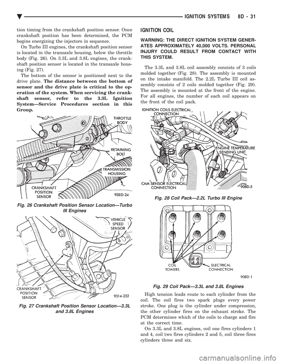
begins energizing the injectors in sequence.On Turbo III engines, the crankshaft position sensor
is located in the transaxle housing, below the throttle
body (Fig. 26). On 3.3L and 3.8L engines, the crank-
shaft position sensor is located in the transaxle hous-
ing (Fig. 27). The bottom of the sensor is positioned next to the
drive plate. The distance between the bottom of
sensor and the drive plate is critical to the op-
eration of the system. When servicing the crank-
shaft sensor, refer to the 3.3L Ignition
SystemÐService Procedures section in this
Group.IGNITION COIL
WARNING: THE DIRECT IGNITION SYSTEM GENER-
ATES APPROXIMATELY 40,000 VOLTS. PERSONAL
INJURY COULD RESULT FROM CONTACT WITH
THIS SYSTEM.
The 3.3L and 3.8L coil assembly consists of 3 coils
molded together (Fig. 28). The assembly is mounted
on the intake manifold. The 2.2L Turbo III coil as-
sembly consists of 2 coils molded together (Fig. 29).
The assembly is mounted at the front of the engine.
For all engines, the number of each coil appears on
the front of the coil pack.
High tension leads route to each cylinder from the
coil. The coil fires two spark plugs every power
stroke. One plug is the cylinder under compression,
the other cylinder fires on the exhaust stroke. The
PCM determines which of the coils to charge and fire
at the correct time. On 3.3L and 3.8L engines, coil one fires cylinders 1
and 4, coil two fires cylinders 2 and 5, coil three fires
cylinders three and six.
Fig. 28 Coil PackÐ2.2L Turbo III Engine
Fig. 29 Coil PackÐ3.3L and 3.8L Engines
Fig. 26 Crankshaft Position Sensor LocationÐTurbo III Engines
Fig. 27 Crankshaft Position Sensor LocationÐ3.3Land 3.8L Engines
Ä IGNITION SYSTEMS 8D - 31
Page 474 of 2438
The coil's low primary resistance allows the PCM to
fully charge the coil for each firing.
COOLANT TEMPERATURE SENSOR
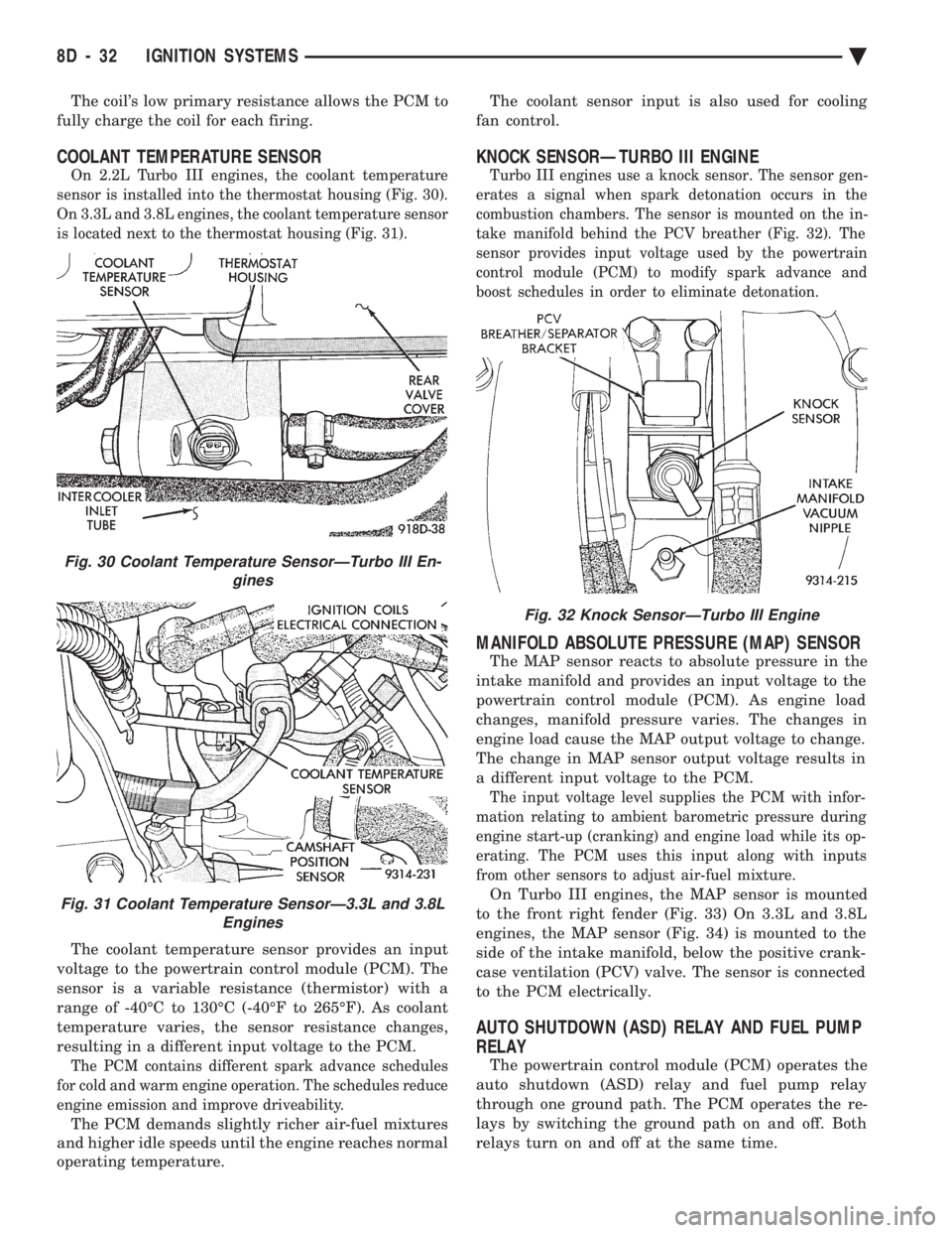
On 2.2L Turbo III engines, the coolant temperature
sensor is installed into the thermostat housing (Fig. 30).
On 3.3L and 3.8L engines, the coolant temperature sensor
is located next to the thermostat housing (Fig. 31).
The coolant temperature sensor provides an input
voltage to the powertrain control module (PCM). The
sensor is a variable resistance (thermistor) with a
range of -40ÉC to 130ÉC (-40ÉF to 265ÉF). As coolant
temperature varies, the sensor resistance changes,
resulting in a different input voltage to the PCM.
The PCM contains different spark advance schedules
for cold and warm engine operation. The schedules reduce
engine emission and improve driveability.
The PCM demands slightly richer air-fuel mixtures
and higher idle speeds until the engine reaches normal
operating temperature. The coolant sensor input is also used for cooling
fan control.
KNOCK SENSORÐTURBO III ENGINE
Turbo III engines use a knock sensor. The sensor gen-
erates a signal when spark detonation occurs in the
combustion chambers. The sensor is mounted on the in-
take manifold behind the PCV breather (Fig. 32). The
sensor provides input voltage used by the powertrain
control module (PCM) to modify spark advance and
boost schedules in order to eliminate detonation.
MANIFOLD ABSOLUTE PRESSURE (MAP) SENSOR
The MAP sensor reacts to absolute pressure in the
intake manifold and provides an input voltage to the
powertrain control module (PCM). As engine load
changes, manifold pressure varies. The changes in
engine load cause the MAP output voltage to change.
The change in MAP sensor output voltage results in
a different input voltage to the PCM.
The input voltage level supplies the PCM with infor-
mation relating to ambient barometric pressure during
engine start-up (cranking) and engine load while its op-
erating. The PCM uses this input along with inputs
from other sensors to adjust air-fuel mixture.
On Turbo III engines, the MAP sensor is mounted
to the front right fender (Fig. 33) On 3.3L and 3.8L
engines, the MAP sensor (Fig. 34) is mounted to the
side of the intake manifold, below the positive crank-
case ventilation (PCV) valve. The sensor is connected
to the PCM electrically.
AUTO SHUTDOWN (ASD) RELAY AND FUEL PUMP
RELAY
The powertrain control module (PCM) operates the
auto shutdown (ASD) relay and fuel pump relay
through one ground path. The PCM operates the re-
lays by switching the ground path on and off. Both
relays turn on and off at the same time.
Fig. 32 Knock SensorÐTurbo III Engine
Fig. 30 Coolant Temperature SensorÐTurbo III En- gines
Fig. 31 Coolant Temperature SensorÐ3.3L and 3.8LEngines
8D - 32 IGNITION SYSTEMS Ä
Page 475 of 2438
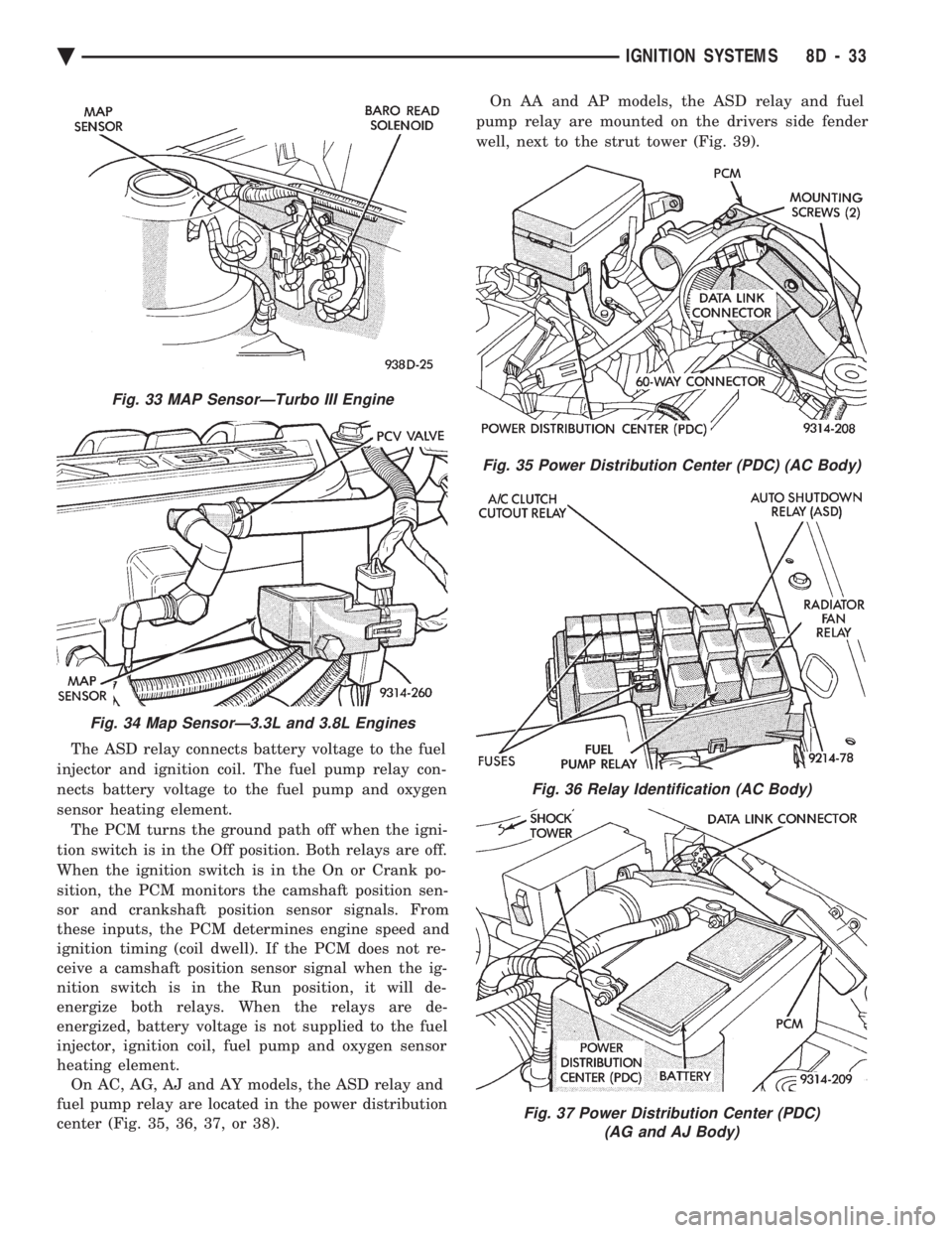
The ASD relay connects battery voltage to the fuel
injector and ignition coil. The fuel pump relay con-
nects battery voltage to the fuel pump and oxygen
sensor heating element. The PCM turns the ground path off when the igni-
tion switch is in the Off position. Both relays are off.
When the ignition switch is in the On or Crank po-
sition, the PCM monitors the camshaft position sen-
sor and crankshaft position sensor signals. From
these inputs, the PCM determines engine speed and
ignition timing (coil dwell). If the PCM does not re-
ceive a camshaft position sensor signal when the ig-
nition switch is in the Run position, it will de-
energize both relays. When the relays are de-
energized, battery voltage is not supplied to the fuel
injector, ignition coil, fuel pump and oxygen sensor
heating element. On AC, AG, AJ and AY models, the ASD relay and
fuel pump relay are located in the power distribution
center (Fig. 35, 36, 37, or 38). On AA and AP models, the ASD relay and fuel
pump relay are mounted on the drivers side fender
well, next to the strut tower (Fig. 39).
Fig. 33 MAP SensorÐTurbo III Engine
Fig. 34 Map SensorÐ3.3L and 3.8L Engines
Fig. 35 Power Distribution Center (PDC) (AC Body)
Fig. 36 Relay Identification (AC Body)
Fig. 37 Power Distribution Center (PDC) (AG and AJ Body)
Ä IGNITION SYSTEMS 8D - 33
Page 476 of 2438
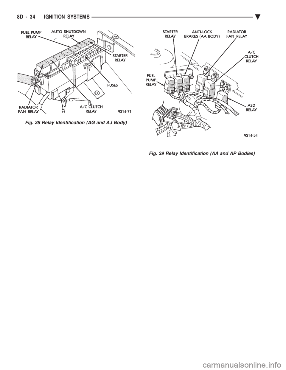
Fig. 39 Relay Identification (AA and AP Bodies)
Fig. 38 Relay Identification (AG and AJ Body)
8D - 34 IGNITION SYSTEMS Ä
Page 477 of 2438
2.2L TURBO III, 3.3L AND 3.8L IGNITION SYSTEMÐDIAGNOSTIC PROCEDURES INDEX
page page
Check Coil TestÐ3.3L and 3.8L Engines ...... 36
Check Coil TestÐTurbo III Engine ........... 35
Coolant Temperature Sensor Test ............ 38
Crankshaft Position Sensor and Camshaft Position Sensor Tests .......................... 38 Failure to Start Test
...................... 37
Failure to Start TestÐTurbo III Engine ........ 36
Manifold Absolute Pressure (MAP) Sensor Test . 38
Testing for Spark at CoilÐ3.3L and 3.8L Engines . 36
Testing for Spark at CoilÐTurbo III Engine ..... 35
TESTING FOR SPARK AT COILÐTURBO III ENGINE
WARNING: THE DIRECT IGNITION SYSTEM GENER-
ATES APPROXIMATELY 40,000 VOLTS. PERSONAL
INJURY COULD RESULT FROM CONTACT WITH
THIS SYSTEM.
The coil pack contains 2 independent coils. Each
coil must be checked individually.
CAUTION: Spark plug wire damage may occur if the
spark plug is moved more than 1/4 inch away from
the engine ground.
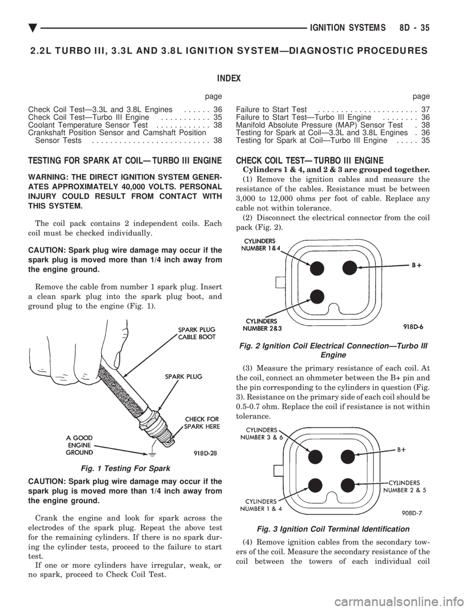
Remove the cable from number 1 spark plug. Insert
a clean spark plug into the spark plug boot, and
ground plug to the engine (Fig. 1).
CAUTION: Spark plug wire damage may occur if the
spark plug is moved more than 1/4 inch away from
the engine ground. Crank the engine and look for spark across the
electrodes of the spark plug. Repeat the above test
for the remaining cylinders. If there is no spark dur-
ing the cylinder tests, proceed to the failure to start
test. If one or more cylinders have irregular, weak, or
no spark, proceed to Check Coil Test.
CHECK COIL TESTÐTURBO III ENGINE
Cylinder s1&4,and2&3are grouped together.
(1) Remove the ignition cables and measure the
resistance of the cables. Resistance must be between
3,000 to 12,000 ohms per foot of cable. Replace any
cable not within tolerance. (2) Disconnect the electrical connector from the coil
pack (Fig. 2).
(3) Measure the primary resistance of each coil. At
the coil, connect an ohmmeter between the B+ pin and
the pin corresponding to the cylinders in question (Fig.
3). Resistance on the primary side of each coil should be
0.5-0.7 ohm. Replace the coil if resistance is not within
tolerance.
(4) Remove ignition cables from the secondary tow-
ers of the coil. Measure the secondary resistance of the
coil between the towers of each individual coil
Fig. 1 Testing For Spark
Fig. 2 Ignition Coil Electrical ConnectionÐTurbo III Engine
Fig. 3 Ignition Coil Terminal Identification
Ä IGNITION SYSTEMS 8D - 35
Page 478 of 2438
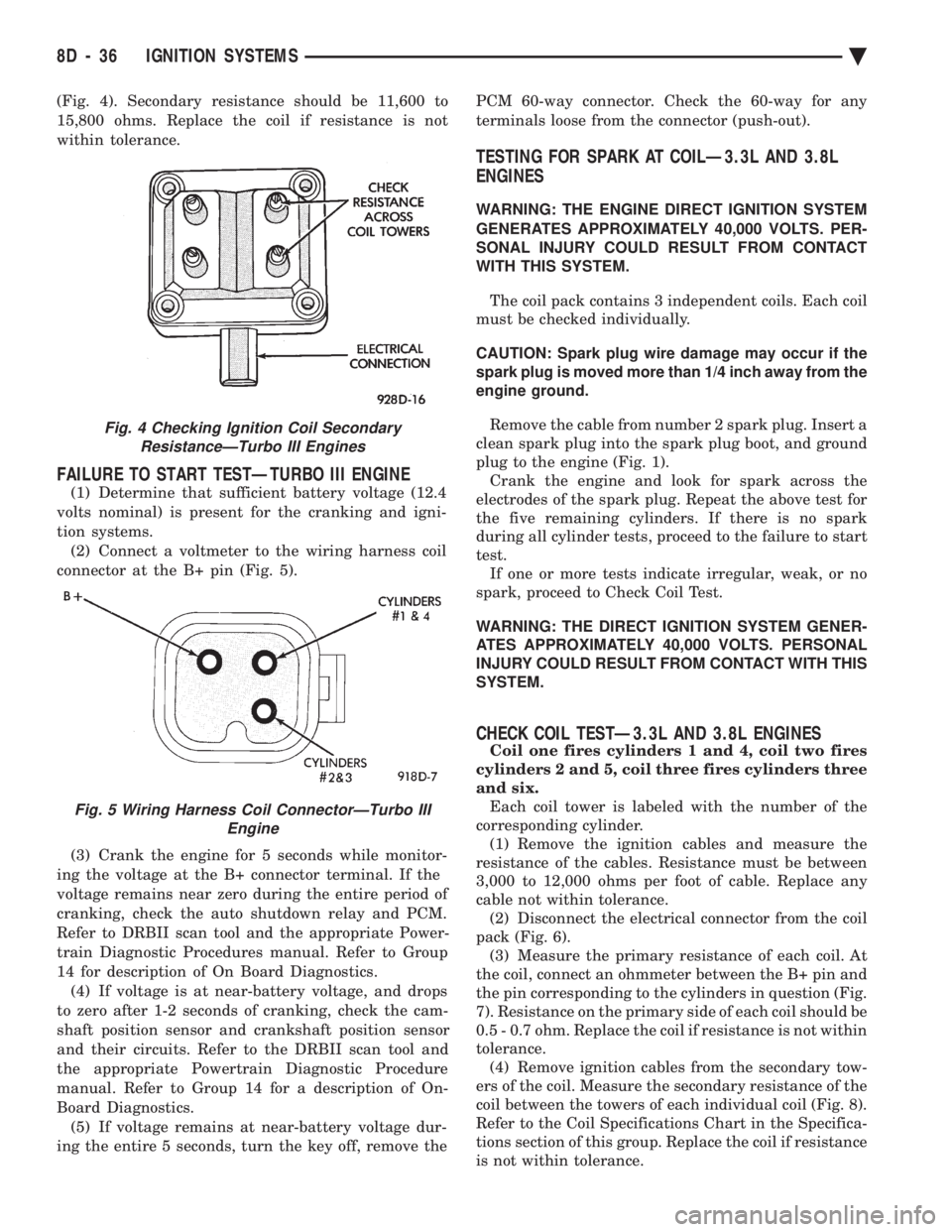
(Fig. 4). Secondary resistance should be 11,600 to
15,800 ohms. Replace the coil if resistance is not
within tolerance.
FAILURE TO START TESTÐTURBO III ENGINE
(1) Determine that sufficient battery voltage (12.4
volts nominal) is present for the cranking and igni-
tion systems. (2) Connect a voltmeter to the wiring harness coil
connector at the B+ pin (Fig. 5).
(3) Crank the engine for 5 seconds while monitor-
ing the voltage at the B+ connector terminal. If the
voltage remains near zero during the entire period of
cranking, check the auto shutdown relay and PCM.
Refer to DRBII scan tool and the appropriate Power-
train Diagnostic Procedures manual. Refer to Group
14 for description of On Board Diagnostics. (4) If voltage is at near-battery voltage, and drops
to zero after 1-2 seconds of cranking, check the cam-
shaft position sensor and crankshaft position sensor
and their circuits. Refer to the DRBII scan tool and
the appropriate Powertrain Diagnostic Procedure
manual. Refer to Group 14 for a description of On-
Board Diagnostics. (5) If voltage remains at near-battery voltage dur-
ing the entire 5 seconds, turn the key off, remove the PCM 60-way connector. Check the 60-way for any
terminals loose from the connector (push-out).
TESTING FOR SPARK AT COILÐ3.3L AND 3.8L
ENGINES
WARNING: THE ENGINE DIRECT IGNITION SYSTEM
GENERATES APPROXIMATELY 40,000 VOLTS. PER-
SONAL INJURY COULD RESULT FROM CONTACT
WITH THIS SYSTEM.
The coil pack contains 3 independent coils. Each coil
must be checked individually.
CAUTION: Spark plug wire damage may occur if the
spark plug is moved more than 1/4 inch away from the
engine ground.
Remove the cable from number 2 spark plug. Insert a
clean spark plug into the spark plug boot, and ground
plug to the engine (Fig. 1). Crank the engine and look for spark across the
electrodes of the spark plug. Repeat the above test for
the five remaining cylinders. If there is no spark
during all cylinder tests, proceed to the failure to start
test. If one or more tests indicate irregular, weak, or no
spark, proceed to Check Coil Test.
WARNING: THE DIRECT IGNITION SYSTEM GENER-
ATES APPROXIMATELY 40,000 VOLTS. PERSONAL
INJURY COULD RESULT FROM CONTACT WITH THIS
SYSTEM.
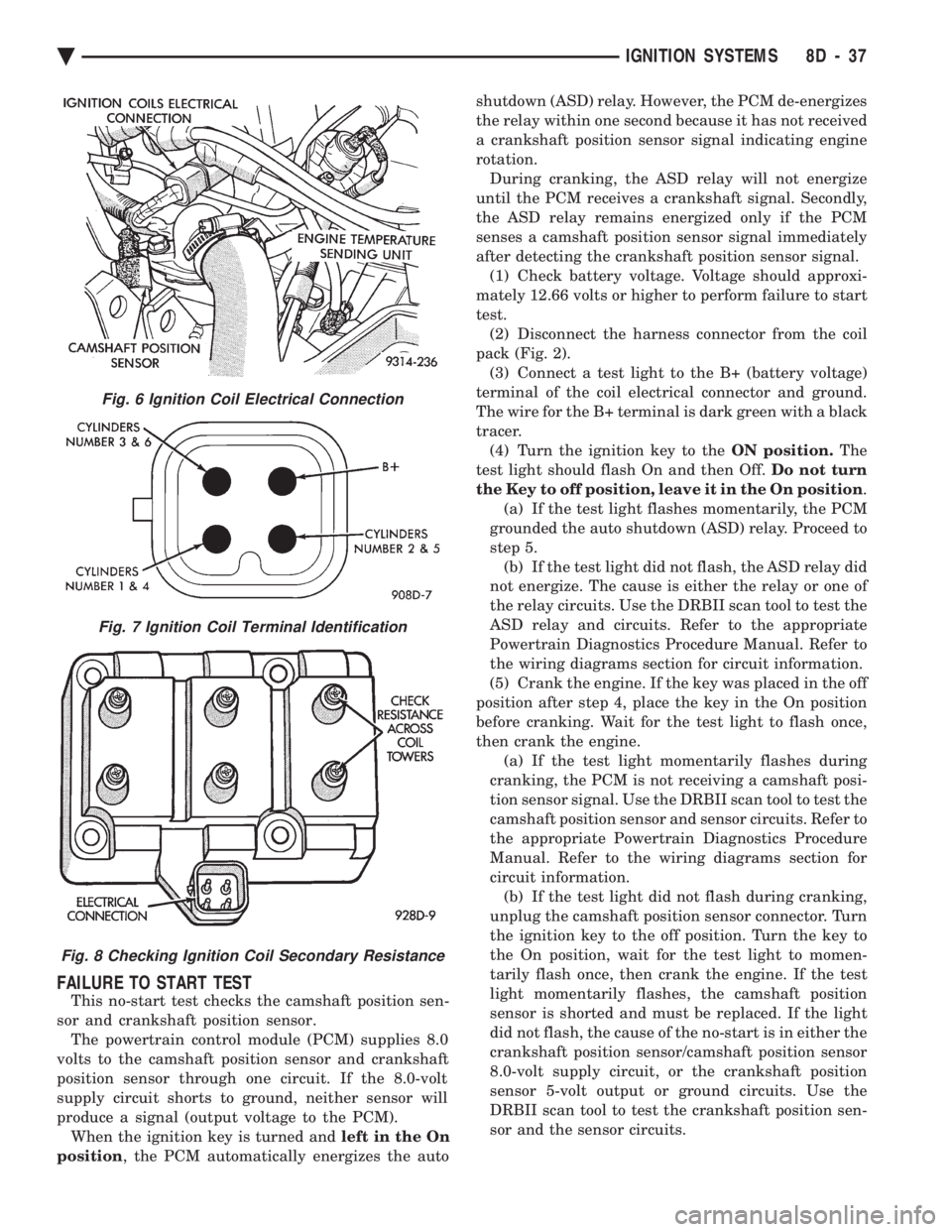
CHECK COIL TESTÐ3.3L AND 3.8L ENGINES
Coil one fires cylinders 1 and 4, coil two fires
cylinders 2 and 5, coil three fires cylinders three
and six. Each coil tower is labeled with the number of the
corresponding cylinder. (1) Remove the ignition cables and measure the
resistance of the cables. Resistance must be between
3,000 to 12,000 ohms per foot of cable. Replace any
cable not within tolerance. (2) Disconnect the electrical connector from the coil
pack (Fig. 6). (3) Measure the primary resistance of each coil. At
the coil, connect an ohmmeter between the B+ pin and
the pin corresponding to the cylinders in question (Fig.
7). Resistance on the primary side of each coil should be
0.5 - 0.7 ohm. Replace the coil if resistance is not within
tolerance. (4) Remove ignition cables from the secondary tow-
ers of the coil. Measure the secondary resistance of the
coil between the towers of each individual coil (Fig. 8).
Refer to the Coil Specifications Chart in the Specifica-
tions section of this group. Replace the coil if resistance
is not within tolerance.
Fig. 4 Checking Ignition Coil Secondary ResistanceÐTurbo III Engines
Fig. 5 Wiring Harness Coil ConnectorÐTurbo III Engine
8D - 36 IGNITION SYSTEMS Ä
Page 479 of 2438
FAILURE TO START TEST
This no-start test checks the camshaft position sen-
sor and crankshaft position sensor. The powertrain control module (PCM) supplies 8.0
volts to the camshaft position sensor and crankshaft
position sensor through one circuit. If the 8.0-volt
supply circuit shorts to ground, neither sensor will
produce a signal (output voltage to the PCM). When the ignition key is turned and left in the On
position , the PCM automatically energizes the auto shutdown (ASD) relay. However, the PCM de-energizes
the relay within one second because it has not received
a crankshaft position sensor signal indicating engine
rotation.
During cranking, the ASD relay will not energize
until the PCM receives a crankshaft signal. Secondly,
the ASD relay remains energized only if the PCM
senses a camshaft position sensor signal immediately
after detecting the crankshaft position sensor signal. (1) Check battery voltage. Voltage should approxi-
mately 12.66 volts or higher to perform failure to start
test. (2) Disconnect the harness connector from the coil
pack (Fig. 2). (3) Connect a test light to the B+ (battery voltage)
terminal of the coil electrical connector and ground.
The wire for the B+ terminal is dark green with a black
tracer. (4) Turn the ignition key to the ON position.The
test light should flash On and then Off. Do not turn
the Key to off position, leave it in the On position .
(a) If the test light flashes momentarily, the PCM
grounded the auto shutdown (ASD) relay. Proceed to
step 5. (b) If the test light did not flash, the ASD relay did
not energize. The cause is either the relay or one of
the relay circuits. Use the DRBII scan tool to test the
ASD relay and circuits. Refer to the appropriate
Powertrain Diagnostics Procedure Manual. Refer to
the wiring diagrams section for circuit information.
(5) Crank the engine. If the key was placed in the off
position after step 4, place the key in the On position
before cranking. Wait for the test light to flash once,
then crank the engine. (a) If the test light momentarily flashes during
cranking, the PCM is not receiving a camshaft posi-
tion sensor signal. Use the DRBII scan tool to test the
camshaft position sensor and sensor circuits. Refer to
the appropriate Powertrain Diagnostics Procedure
Manual. Refer to the wiring diagrams section for
circuit information. (b) If the test light did not flash during cranking,
unplug the camshaft position sensor connector. Turn
the ignition key to the off position. Turn the key to
the On position, wait for the test light to momen-
tarily flash once, then crank the engine. If the test
light momentarily flashes, the camshaft position
sensor is shorted and must be replaced. If the light
did not flash, the cause of the no-start is in either the
crankshaft position sensor/camshaft position sensor
8.0-volt supply circuit, or the crankshaft position
sensor 5-volt output or ground circuits. Use the
DRBII scan tool to test the crankshaft position sen-
sor and the sensor circuits.
Fig. 6 Ignition Coil Electrical Connection
Fig. 7 Ignition Coil Terminal Identification
Fig. 8 Checking Ignition Coil Secondary Resistance
Ä IGNITION SYSTEMS 8D - 37
Page 480 of 2438
Refer to the appropriate Powertrain Diagnostics Pro-
cedure Manual. Refer to the wiring diagrams section
for circuit information.
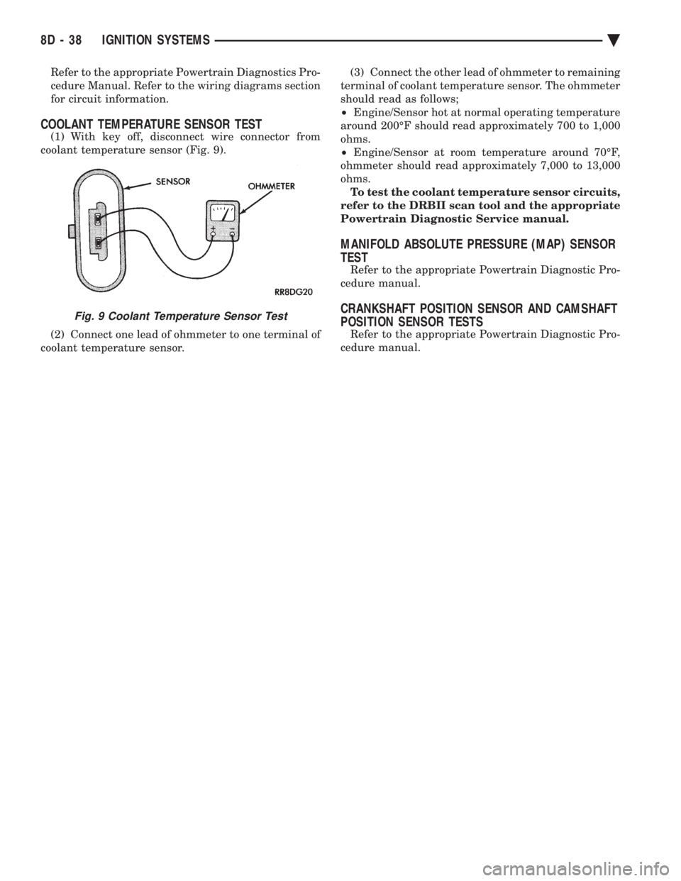
COOLANT TEMPERATURE SENSOR TEST
(1) With key off, disconnect wire connector from
coolant temperature sensor (Fig. 9).
(2) Connect one lead of ohmmeter to one terminal of
coolant temperature sensor. (3) Connect the other lead of ohmmeter to remaining
terminal of coolant temperature sensor. The ohmmeter
should read as follows;
² Engine/Sensor hot at normal operating temperature
around 200ÉF should read approximately 700 to 1,000
ohms.
² Engine/Sensor at room temperature around 70ÉF,
ohmmeter should read approximately 7,000 to 13,000
ohms. To test the coolant temperature sensor circuits,
refer to the DRBII scan tool and the appropriate
Powertrain Diagnostic Service manual.
MANIFOLD ABSOLUTE PRESSURE (MAP) SENSOR
TEST
Refer to the appropriate Powertrain Diagnostic Pro-
cedure manual.
CRANKSHAFT POSITION SENSOR AND CAMSHAFT
POSITION SENSOR TESTS
Refer to the appropriate Powertrain Diagnostic Pro-
cedure manual.
Fig. 9 Coolant Temperature Sensor Test
8D - 38 IGNITION SYSTEMS Ä