fig. 78 CHRYSLER CARAVAN 2002 Service Manual
[x] Cancel search | Manufacturer: CHRYSLER, Model Year: 2002, Model line: CARAVAN, Model: CHRYSLER CARAVAN 2002Pages: 2399, PDF Size: 57.96 MB
Page 523 of 2399

DIAGNOSIS AND TESTING - MULTI-FUNCTION
SWITCH
To test turn signal, headlamp beam select and opti-
cal horn portion of the multi-function switch:
(1) Remove the multi-function switch, refer to
Electrical, Lamps/Lighting - Exterior, Multi-Function
Switch, Removal, and Installation.
(2) Using an ohmmeter check the resistance read-
ings between multi-function switch pins. Refer to
Wiring Diagrams for proper pin numbers and the
MULTI-FUNCTION SWITCH RESISTANCE table.
MULTI-FUNCTION SWITCH RESISTANCE
SWITCH
POSITIONPIN NUMBER RESISTANCE
LEFT 2 AND 3 1.7V 5%
RIGHT 2 AND 3 1KV 5%
OPTICAL
HORN1 AND 3 4.87KV 5%
HI BEAM 1 AND 3 2.32KV 5%
REMOVAL
(1) Disconnect and isolate battery negative cable.
(2) Remove upper and lower steering column
shrouds. Refer to Steering, Column, Shroud,
Removal.
(3) Disconnect wire connector from back of multi-
function switch.
(4) Remove screws holding multi-function switch to
steering column adapter collar.
(5) Remove the multi-function switch.
INSTALLATION
(1) Position the switch on to the steering column.
(2) Install the two retaining screws.
(3) Connect the wire harness connector.
(4) Install the upper and lower steering column
shrouds. Refer to Steering, Column, Shroud, Installa-
tion.
(5) Connect the battery negative cable.
PARK/TURN SIGNAL LAMP
REMOVAL
(1) Disconnect and isolate battery negative cable.
(2) Remove headlamp retaining screws.
(3) Twist socket counter - clockwise and remove
(Fig. 26).
(4) Pull bulb from socket.
INSTALLATION
(1) Push bulb into socket.
(2) Twist socket into headlamp.(3) Install headlamp retaining screws.
(4) Reconnect battery negative cable.
PARK/TURN SIGNAL LAMP -
EXPORT
REMOVAL
(1) Disconnect and isolate the battery negative
cable.
(2) Remove the headlamp unit.
(3) Twist bulb socket and remove from headlamp
unit (Fig. 27).
(4) Twist bulb and remove from bulb socket.
Fig. 26 PARK/TURN SIGNAL LAMP
1 - PARK/TURN SIGNAL LAMP
2 - LAMP SOCKET
Fig. 27 PARK/TURN SIGNAL LAMP
1 - LOW BEAM HEADLAMP
2 - PARK/TURN SIGNAL LAMP
8L - 22 LAMPS/LIGHTING - EXTERIORRS
MULTI-FUNCTION SWITCH (Continued)
ProCarManuals.com
Page 524 of 2399

INSTALLATION
(1) Install bulb to bulb socket.
(2) Install bulb socket to headlamp unit.
(3) Install headlamp unit.
(4) Connect battery negative cable.
REAR FOG LAMP - EXPORT
DESCRIPTION
The rear fog lamps are incorporated into the tail
lamp unit. (Refer to 8 - ELECTRICAL/LAMPS/
LIGHTING - EXTERIOR/TAIL LAMP - REMOVAL)
for service procedures.
REPEATER LAMP - EXPORT
REMOVAL
(1) Disconnect and isolate the battery negative
cable.
(2) Push the side repeater lamp to one side and
release retaining tab.
(3) Pull side repeater lamp out and disengage bulb
socket from lamp.
(4) Depress, then rotate and pull bulb from socket.
INSTALLATION
(1) Install bulb to socket.
(2) Push lamp socket into the side repeater lamp.
(3) Position side repeater lamp to hole in fender.
(4) Push side repeater lamp to one side and seat
retaining tab into fender.
(5) Connect battery negative cable.
TAIL LAMP
REMOVAL
(1) Disconnect and isolate the battery negative
cable.
(2) Remove the tail lamp unit. (Refer to 8 - ELEC-
TRICAL/LAMPS/LIGHTING - EXTERIOR/TAIL
LAMP UNIT - REMOVAL).
(3) Squeeze the tabs on the bulb socket and
remove from tail lamp unit (Fig. 28).
(4) Pull bulb from lamp socket.
INSTALLATION
(1) Push bulb into the lamp socket.
(2) Install bulb socket into the tail lamp unit.
Ensure that both retaining tabs engage with an audi-
ble click.
(3) Install the tail lamp unit. (Refer to 8 - ELEC-
TRICAL/LAMPS/LIGHTING - EXTERIOR/TAIL
LAMP UNIT - INSTALLATION).(4) Reconnect the battery negative cable.
TAIL LAMP - EXPORT
REMOVAL
(1) Disconnect and isolate the battery negative
cable.
(2) Remove the tail lamp unit (Refer to 8 - ELEC-
TRICAL/LAMPS/LIGHTING - EXTERIOR/TAIL
LAMP UNIT - REMOVAL).
(3) Squeeze the tabs on housing retaining the
bulbs and remove from the tail lamp unit (Fig. 29).
(4) Remove bulbs by depressing, then turning
counter-clockwise.
Fig. 28 TAIL LAMP SOCKET
1 - LAMP SOCKET
2 - TAIL LAMP UNIT
Fig. 29 TAIL LAMP BULBS
1 - TAIL LAMP UNIT
2 - BRAKE/PARK LAMP
3 - TURN SIGNAL LAMP
4 - BACK UP LAMP
5 - REAR FOG LAMP
RSLAMPS/LIGHTING - EXTERIOR8L-23
PARK/TURN SIGNAL LAMP - EXPORT (Continued)
ProCarManuals.com
Page 525 of 2399
INSTALLATION
(1) Install bulbs by turning clockwise.
(2) Install housing to tail lamp unit.
(3) Install the tail lamp unit (Refer to 8 - ELEC-
TRICAL/LAMPS/LIGHTING - EXTERIOR/TAIL
LAMP UNIT - INSTALLATION).
(4) Connect the battery negative cable.
TAIL LAMP UNIT
REMOVAL
(1) Disconnect and isolate the battery negative
cable.
(2) Raise the liftgate.
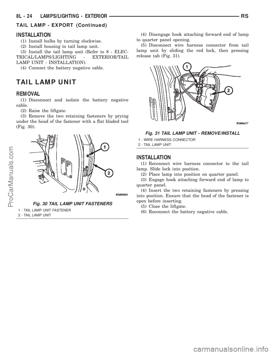
(3) Remove the two retaining fasteners by prying
under the head of the fastener with a flat bladed tool
(Fig. 30).(4) Disengage hook attaching forward end of lamp
to quarter panel opening.
(5) Disconnect wire harness connector from tail
lamp unit by sliding the red lock, then pressing
release tab (Fig. 31).
INSTALLATION
(1) Reconnect wire harness connector to the tail
lamp. Slide lock into position.
(2) Place lamp into position on quarter panel.
(3) Engage hook attaching forward end of lamp to
quarter panel.
(4) Insert the two retaining fasteners by pressing
into position. Ensure that the head of the fastener is
open before inserting.
(5) Close the liftgate.
(6) Reconnect the battery negative cable.
Fig. 30 TAIL LAMP UNIT FASTENERS
1 - TAIL LAMP UNIT FASTENER
2 - TAIL LAMP UNIT
Fig. 31 TAIL LAMP UNIT - REMOVE/INSTALL
1 - WIRE HARNESS CONNECTOR
2 - TAIL LAMP UNIT
8L - 24 LAMPS/LIGHTING - EXTERIORRS
TAIL LAMP - EXPORT (Continued)
ProCarManuals.com
Page 527 of 2399
CENTER CONSOLE LAMP
SWITCH
REMOVAL
(1)Disconnect and isolate the battery negative cable.
(2) Open console lid and remove tray.
(3) Using a flat bladed tool, pry up on the switch.
(4) Remove bulb from switch.
INSTALLATION
(1) Install bulb into switch.
(2) Push switch into console opening.
(3) Install tray and close lid.
(4) Connect battery negative cable.
CLUSTER ILLUMINATION
LAMPS
REMOVAL
(1) Remove the Instrument Cluster. Refer to Elec-
trical, Instrument Cluster, Removal.
(2) Turn over cluster and expose the illumination
bulb sockets.
(3) Identify which bulb is defective and twist it out
of the cluster using a counterclockwise motion.
INSTALLATION
(1) Install the new bulb socket into the cluster
using a clockwise motion.
(2) Install the Instrument Cluster. Refer to Electri-
cal, Instrument Cluster, Installation.
COURTESY LAMP
REMOVAL
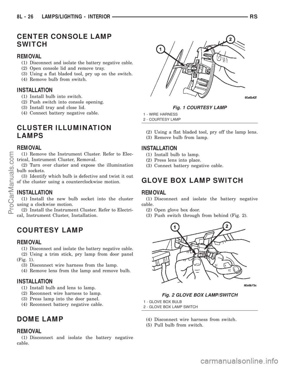
(1)Disconnect and isolate the battery negative cable.
(2) Using a trim stick, pry lamp from door panel
(Fig. 1).
(3) Disconnect wire harness from the lamp.
(4) Remove lens from the lamp and remove bulb.
INSTALLATION
(1) Install bulb and lens to lamp.
(2) Reconnect wire harness to lamp.
(3) Press lamp into the door panel.
(4) Reconnect battery negative cable.
DOME LAMP
REMOVAL
(1) Disconnect and isolate the battery negative
cable.(2) Using a flat bladed tool, pry off the lamp lens.
(3) Remove bulb from lamp.
INSTALLATION
(1) Install bulb to lamp.
(2) Press lens into place.
(3) Connect battery negative cable.
GLOVE BOX LAMP SWITCH
REMOVAL
(1) Disconnect and isolate the battery negative
cable.
(2) Open glove box door.
(3) Push switch through from behind (Fig. 2).
(4) Disconnect wire harness from switch.
(5) Pull bulb from switch.
Fig. 1 COURTESY LAMP
1 - WIRE HARNESS
2 - COURTESY LAMP
Fig. 2 GLOVE BOX LAMP/SWITCH
1 - GLOVE BOX BULB
2 - GLOVE BOX LAMP SWITCH
8L - 26 LAMPS/LIGHTING - INTERIORRS
ProCarManuals.com
Page 528 of 2399
INSTALLATION
(1) Push bulb into switch.
(2) Connect wire harness to switch.
(3) Push switch into instrument panel.
(4) Close glove box door.
(5) Reconnect the battery negative cable.
LIFTGATE LAMP
REMOVAL
(1) Disconnect and isolate the battery negative
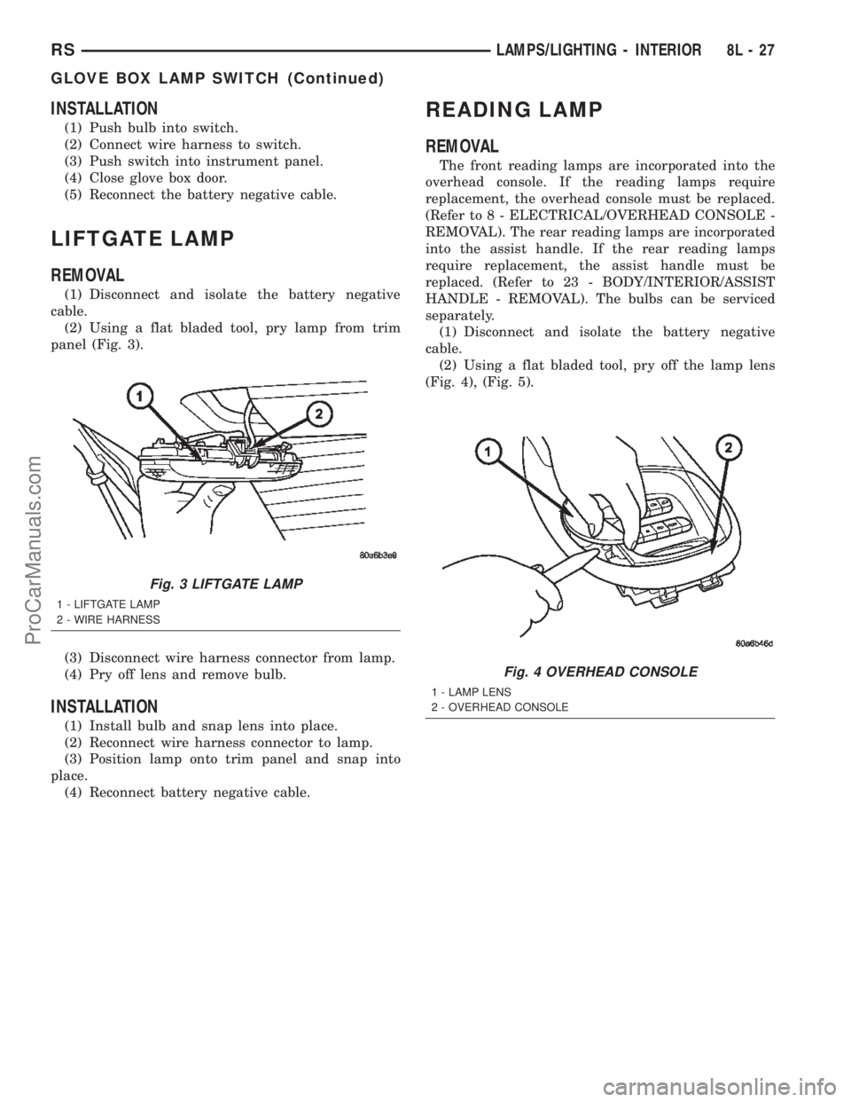
cable.
(2) Using a flat bladed tool, pry lamp from trim
panel (Fig. 3).
(3) Disconnect wire harness connector from lamp.
(4) Pry off lens and remove bulb.
INSTALLATION
(1) Install bulb and snap lens into place.
(2) Reconnect wire harness connector to lamp.
(3) Position lamp onto trim panel and snap into
place.
(4) Reconnect battery negative cable.
READING LAMP
REMOVAL
The front reading lamps are incorporated into the
overhead console. If the reading lamps require
replacement, the overhead console must be replaced.
(Refer to 8 - ELECTRICAL/OVERHEAD CONSOLE -
REMOVAL). The rear reading lamps are incorporated
into the assist handle. If the rear reading lamps
require replacement, the assist handle must be
replaced. (Refer to 23 - BODY/INTERIOR/ASSIST
HANDLE - REMOVAL). The bulbs can be serviced
separately.
(1) Disconnect and isolate the battery negative
cable.
(2) Using a flat bladed tool, pry off the lamp lens
(Fig. 4), (Fig. 5).
Fig. 3 LIFTGATE LAMP
1 - LIFTGATE LAMP
2 - WIRE HARNESS
Fig. 4 OVERHEAD CONSOLE
1 - LAMP LENS
2 - OVERHEAD CONSOLE
RSLAMPS/LIGHTING - INTERIOR8L-27
GLOVE BOX LAMP SWITCH (Continued)
ProCarManuals.com
Page 529 of 2399

(3) Remove bulb from lamp (Fig. 6), (Fig. 7).
INSTALLATION
(1) Install bulb to lamp.
(2) Press lens into place.
(3) Reconnect the battery negative cable.
VANITY LAMP
REMOVAL
The vanity lamp is incorporated into the visor
assembly. If the vanity lamp needs to be replaced,
the entire visor must be replaced. The bulbs are ser-
viced separately.(1) Disconnect and isolate the battery negative
cable.
(2) Using a pick or other suitable tool, pry the
lens from the lamp (Fig. 8).
(3) Remove bulb.
INSTALLATION
(1) Install bulb.
(2) Snap lamp lens into position.
(3) Connect the battery negative cable.
Fig. 5 COURTESY/READING LAMP
1 - HVAC LOUVER
2 - ASSIST HANDLE
3 - LAMP LENS
Fig. 6 OVERHEAD CONSOLE LAMP
1 - LAMP
2 - OVERHEAD CONSOLE
Fig. 7 COURTESY/READING LAMP
1 - COURTESY/READING LAMP
Fig. 8 VANITY LAMP
1 - VISOR
2 - VISOR/VANITY LAMP
3 - LENS
8L - 28 LAMPS/LIGHTING - INTERIORRS
READING LAMP (Continued)
ProCarManuals.com
Page 533 of 2399
STANDARD PROCEDURE - COMPASS
DEMAGNETIZING
A degaussing tool (Special Tool 6029) is used to
demagnetize, or degauss, the overhead console for-
ward mounting screw and the roof panel above the
overhead console. Equivalent units must be rated as
continuous duty for 110/115 volts and 60 Hz. They
must also have a field strength of over 350 gauss at 7
millimeters (0.25 inch) beyond the tip of the probe.
To demagnetize the roof panel and the overhead
console forward mounting screw, proceed as follows:
(1) Be certain that the ignition switch is in the Off
position, before you begin the demagnetizing proce-
dure.
(2) Connect the degaussing tool to an electrical
outlet, while keeping the tool at least 61 centimeters
(2 feet) away from the compass unit.
(3) Slowly approach the head of the overhead con-
sole forward mounting screw with the degaussing
tool connected.
(4) Contact the head of the screw with the plastic
coated tip of the degaussing tool for about two sec-
onds.
(5) With the degaussing tool still energized, slowly
back it away from the screw. When the tip of the tool
is at least 61 centimeters (2 feet) from the screw
head, disconnect the tool.
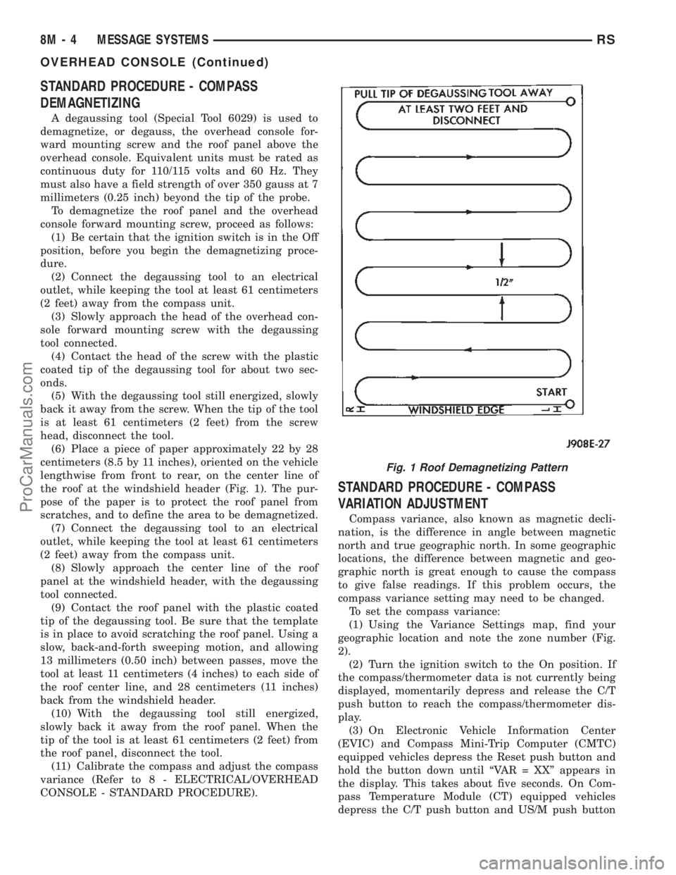
(6) Place a piece of paper approximately 22 by 28
centimeters (8.5 by 11 inches), oriented on the vehicle
lengthwise from front to rear, on the center line of
the roof at the windshield header (Fig. 1). The pur-
pose of the paper is to protect the roof panel from
scratches, and to define the area to be demagnetized.
(7) Connect the degaussing tool to an electrical
outlet, while keeping the tool at least 61 centimeters
(2 feet) away from the compass unit.
(8) Slowly approach the center line of the roof
panel at the windshield header, with the degaussing
tool connected.
(9) Contact the roof panel with the plastic coated
tip of the degaussing tool. Be sure that the template
is in place to avoid scratching the roof panel. Using a
slow, back-and-forth sweeping motion, and allowing
13 millimeters (0.50 inch) between passes, move the
tool at least 11 centimeters (4 inches) to each side of
the roof center line, and 28 centimeters (11 inches)
back from the windshield header.
(10) With the degaussing tool still energized,
slowly back it away from the roof panel. When the
tip of the tool is at least 61 centimeters (2 feet) from
the roof panel, disconnect the tool.
(11) Calibrate the compass and adjust the compass
variance (Refer to 8 - ELECTRICAL/OVERHEAD
CONSOLE - STANDARD PROCEDURE).
STANDARD PROCEDURE - COMPASS
VARIATION ADJUSTMENT
Compass variance, also known as magnetic decli-
nation, is the difference in angle between magnetic
north and true geographic north. In some geographic
locations, the difference between magnetic and geo-
graphic north is great enough to cause the compass
to give false readings. If this problem occurs, the
compass variance setting may need to be changed.
To set the compass variance:
(1) Using the Variance Settings map, find your
geographic location and note the zone number (Fig.
2).
(2) Turn the ignition switch to the On position. If
the compass/thermometer data is not currently being
displayed, momentarily depress and release the C/T
push button to reach the compass/thermometer dis-
play.
(3) On Electronic Vehicle Information Center
(EVIC) and Compass Mini-Trip Computer (CMTC)
equipped vehicles depress the Reset push button and
hold the button down until ªVAR = XXº appears in
the display. This takes about five seconds. On Com-
pass Temperature Module (CT) equipped vehicles
depress the C/T push button and US/M push button
Fig. 1 Roof Demagnetizing Pattern
8M - 4 MESSAGE SYSTEMSRS
OVERHEAD CONSOLE (Continued)
ProCarManuals.com
Page 534 of 2399

down until ªVAR = XXº appears in the display. This
takes about five seconds.
(4) Release the push button(s). ªVAR =XX º will
remain in the display. ªXXº equals the current vari-
ance zone setting.
(5) On Electronic Vehicle Information Center
(EVIC) and Compass Mini-Trip Computer (CMTC)
equipped vehicles momentarily depress and release
theStep push buttonto step through the zone
numbers, until the zone number for your geographic
location appears in the display. On Compass Temper-
ature Module (CT) equipped vehicles depress the
US/M push buttonto step through the zone num-
bers, until the zone number for your geographic loca-
tion appears in the display.
(6) On Electronic Vehicle Information Center
(EVIC) and Compass Mini-Trip Computer (CMTC)
equipped vehicles momentarily depress and release
theReset push buttonto enter the displayed zone
number into the EVIC/CMTC module memory. On
Compass Temperature Module (CT) equipped vehicles
depress theC/T push buttonto enter the displayed
zone number into the electronic module memory.
(7) Confirm that the correct directions are now
indicated by the compass.
REMOVAL - OVERHEAD CONSOLE
(1) Disconnect and isolate the remote negative bat-
tery cable.(2) Remove the overhead console retaining screw,
located in the front of console.
(3) Using your fingertips, grasp the sides of the
overhead console and pull straight down evenly to
disengage the two snap clips at the rear of the unit.
(4) Lower the overhead console far enough to
access the wire harness connectors.
(5) Disconnect the EVIC, CMTC or CT electronic
module and the reading/courtesy lamps electrical
connector.
(6) Remove the overhead console from the vehicle.
INSTALLATION
(1) Position the overhead console in the vehicle.
(2) Connect the EVIC, CMTC or CT electronic
module and the reading/courtesy lamps electrical
connector.
(3) Using your fingertips, grasp the sides of the
overhead console and push straight up evenly to
engage the two snap clips at the rear of the unit.
CAUTION: DO NOT PRESS ON THE SUNGLASS
STORAGE BIN DOOR. DAMAGE TO THE DOOR MAY
RESULT.
(4) Install the overhead console retaining screw,
located in the front of console. Torque the screw to
1.2 N´m (10 in. lbs.).
(5) Connect the remote negative battery cable.
Fig. 2 Variance Settings
RSMESSAGE SYSTEMS8M-5
OVERHEAD CONSOLE (Continued)
ProCarManuals.com
Page 543 of 2399
POWER LIFTGATE SYSTEM
DESCRIPTION
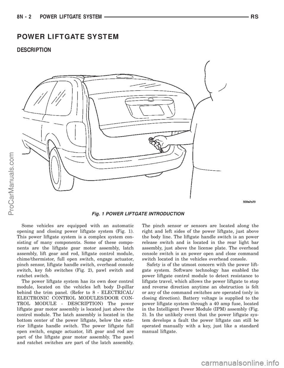
Some vehicles are equipped with an automatic
opening and closing power liftgate system (Fig. 1).
This power liftgate system is a complex system con-
sisting of many components. Some of these compo-
nents are the liftgate gear motor assembly, latch
assembly, lift gear and rod, liftgate control module,
chime/thermistor, full open switch, engage actuator,
pinch sensor, liftgate handle switch, overhead console
switch, key fob switches (Fig. 2), pawl switch and
ratchet switch.
The power liftgate system has its own door control
module, located on the vehicles left body D-pillar
behind the trim panel. (Refer to 8 - ELECTRICAL/
ELECTRONIC CONTROL MODULES/DOOR CON-
TROL MODULE - DESCRIPTION) The power
liftgate gear motor assembly is located just above the
control module. The latch assembly is located in the
bottom center of the power liftgate, below the exte-
rior liftgate handle switch. The power liftgate full
open switch, engage actuator, lift gear and rod are
part of the liftgate gear motor assembly. The pawl
and ratchet switches are part of the latch assembly.The pinch sensor or sensors are located along the
right and left sides of the power liftgate, just above
the body line. The liftgate handle switch is an power
release switch and is located in the rear light bar
assembly, just above the license plate. The overhead
console switch is an power open and close command
switch located in the vehicles overhead console.
Safety is of the utmost concern with the power lift-
gate system. Software technology has enabled the
power liftgate control module to detect resistance to
liftgate travel, which allows the power liftgate to stop
and reverse direction anytime an obstruction is felt
or any of the command switches are operated (only in
closing direction). Battery voltage is supplied to the
power liftgate system through a 40 amp fuse, located
in the Intelligent Power Module (IPM) assembly (Fig.
3). In the unlikely event that the power liftgate sys-
tem develops a fault the power liftgate can still be
operated manually with a key, just like a standard
manual liftgate.
Fig. 1 POWER LIFTGATE INTRODUCTION
8N - 2 POWER LIFTGATE SYSTEMRS
ProCarManuals.com
Page 544 of 2399

The power liftgate control module communicates
on the J1850 Programmable Communication Inter-
face (PCI) Bus Circuit. Therefore, the power liftgate
control module can generate and store its own Diag-
nostic Trouble Codes (DTC). The vehicles Body Con-
trol Module (BCM) receives and supplies messages tothe power liftgate control module via the PCI bus cir-
cuit. A diagnostic scan tool, such as the DRB IIItis
used to read and troubleshoot these Diagnostic Trou-
ble Codes (DTC). Refer to the Body Diagnostic Man-
ual for a complete list of diagnostic routines.
For additional information refer to Power Liftgate
Operation. For a complete system wiring schematic
refer to Wiring Diagrams. For system operation
instructions refer to the vehicles owner manual.
Refer to the Body section of the service manual
for additional information on liftgate components
such as the prop rods, hinges, door alignment and
striker alignment.
WARNING: BE CERTAIN TO READ ALL WARNINGS
AND CAUTIONS (NOTED BELOW) IN POWER LIFT-
GATE SYSTEM OPERATION BEFORE ATTEMPTING
ANY SERVICE OF THE POWER LIFTGATE SYSTEM
OR COMPONENTS.
OPERATION
With the push of a power liftgate open/close com-
mand switch (key fob or overhead console mounted) a
signal is sent out on the J1850 PCI Data Bus circuit.
This signal is detected at the body control module
(BCM). The BCM then sends a signal out on the
J1850 PCI Data Bus circuit to the power liftgate
module. The power liftgate module then signals the
power liftgate motor to start an open or close cycle,
depending on what position the liftgate is in open or
closed.
During a liftgate open or close cycle, if the power
liftgate module detects sufficient resistance to liftgate
travel, such as an obstruction in the liftgates path,
the power liftgate control module will immediately
stop the liftgate movement and reverse travel to the
full open or closed position. The ability for the power
liftgate module to detect resistance to liftgate travel
is accomplished by hall effect sensors, drive motor
speed and pinch sensors (tape switches).
The power liftgate control module has the ability to
learn. Anytime the liftgate is opened or closed using
the power liftgate system the module learns from its
cycle. If a replacement power liftgate component is
installed or a liftgate adjustment is made, the mod-
ule will relearn the effort and/or time required to
open or close the door. This learn cycle can be per-
formed with a Diagnostic Scan Tool, such as the DRB
IIItor with a complete cycle of the liftgate, using
any one of the command switches. Refer to Standard
Procedures in this section for detailed instructions.Fig. 2 KEY FOB
1 - Left Sliding Door Switch
2 - Right Sliding Door Switch
3 - Liftgate Switch
Fig. 3 LIFTGATE FUSE LOCATION
RSPOWER LIFTGATE SYSTEM8N-3
POWER LIFTGATE SYSTEM (Continued)
ProCarManuals.com