engine mount CHRYSLER CARAVAN 2002 Manual PDF
[x] Cancel search | Manufacturer: CHRYSLER, Model Year: 2002, Model line: CARAVAN, Model: CHRYSLER CARAVAN 2002Pages: 2399, PDF Size: 57.96 MB
Page 409 of 2399

(3) To disable the ignition and fuel systems, dis-
connect the Automatic Shutdown Relay (ASD). The
ASD relay is located in the Power Distribution Cen-
ter (PDC). Refer to the PDC cover for proper relay
location.
(4) Verify that all lights and accessories are OFF,
and the transmission shift selector is in the PARK
and SET parking brake.
CAUTION: Do not overheat the starter motor or
draw the battery voltage below 9.6 volts during
cranking operations.
(5) Rotate and hold the ignition switch in the
START position. Observe the volt-ampere tester (Fig.
3).
²If voltage reads above 9.6 volts, and amperage
draw reads above 280 amps, check for engine seizing
or faulty starter.
²If voltage reads 12.4 volts or greater and amper-
age reads 0 to 10 amps, check for corroded cables
and/or bad connections.
²Voltage below 9.6 volts and amperage draw
above 300 amps, the problem is the starter. Replace
the starter refer to starter removal.
(6) After the starting system problems have been
corrected, verify the battery state-of-charge and
charge battery if necessary. Disconnect all testing
equipment and connect ASD relay. Start the vehicle
several times to assure the problem has been cor-
rected.SPECIFICATIONS
STARTER
MANUFACTURER NIPPONDENSO
Engine Application 2.4L /3.3/3.8L
Power rating 1.2 Kw
Voltage 12 VOLTS
No. of Fields 4
No. of Poles 4
Brushes 4
Drive Conventional Gear Train
Free running Test
Voltage 11
Amperage Draw 73 Amp
Minimum Speed 3401 RPM
SolenoidClosing Voltage 7.5 Volts
Cranking Amperage Draw
test150 - 200 Amps.
Engine should be up to operating temperature.
Extremely heavy oil or tight engine will increase
starter amperage draw.
Torques
DESCRIPTION N´m Ft. Lbs. In. Lbs.
Starter Mounting Bolts 47.4 35
Starter Solenoid Battery
Nut11.3 8.3 100
8F - 34 STARTINGRS
STARTING (Continued)
ProCarManuals.com
Page 411 of 2399
REMOVAL - 3.3/3.8L
(1) Release hood latch and open hood.
(2) Disconnect and isolate the battery negative
cable.
(3) Hoist and support vehicle on safety stands.
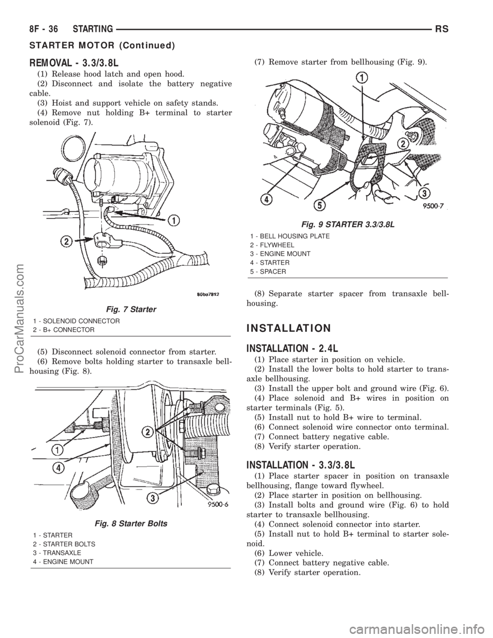
(4) Remove nut holding B+ terminal to starter
solenoid (Fig. 7).
(5) Disconnect solenoid connector from starter.
(6) Remove bolts holding starter to transaxle bell-
housing (Fig. 8).(7) Remove starter from bellhousing (Fig. 9).
(8) Separate starter spacer from transaxle bell-
housing.
INSTALLATION
INSTALLATION - 2.4L
(1) Place starter in position on vehicle.
(2) Install the lower bolts to hold starter to trans-
axle bellhousing.
(3) Install the upper bolt and ground wire (Fig. 6).
(4) Place solenoid and B+ wires in position on
starter terminals (Fig. 5).
(5) Install nut to hold B+ wire to terminal.
(6) Connect solenoid wire connector onto terminal.
(7) Connect battery negative cable.
(8) Verify starter operation.
INSTALLATION - 3.3/3.8L
(1) Place starter spacer in position on transaxle
bellhousing, flange toward flywheel.
(2) Place starter in position on bellhousing.
(3) Install bolts and ground wire (Fig. 6) to hold
starter to transaxle bellhousing.
(4) Connect solenoid connector into starter.
(5) Install nut to hold B+ terminal to starter sole-
noid.
(6) Lower vehicle.
(7) Connect battery negative cable.
(8) Verify starter operation.
Fig. 7 Starter
1 - SOLENOID CONNECTOR
2 - B+ CONNECTOR
Fig. 8 Starter Bolts
1-STARTER
2 - STARTER BOLTS
3 - TRANSAXLE
4 - ENGINE MOUNT
Fig. 9 STARTER 3.3/3.8L
1 - BELL HOUSING PLATE
2 - FLYWHEEL
3 - ENGINE MOUNT
4-STARTER
5 - SPACER
8F - 36 STARTINGRS
STARTER MOTOR (Continued)
ProCarManuals.com
Page 413 of 2399
²Battery Holddown- The battery holddown
hardware secures the battery in the battery tray in
the engine compartment.
²Battery Thermowrap- The battery ther-
mowarp insulates the battery to protect it from
engine compartment temperature extremes.
²Battery Tray- The battery tray provides a
secure mounting location in the vehicle for the bat-
tery and an anchor point for the battery holddown
hardware.
For battery system maintenance schedules and
jump starting procedures, see the owner's manual in
the vehicle glove box. Optionally, refer to Lubrication
and Maintenance for the recommended battery main-
tenance schedules and for the proper battery jump
starting procedures. While battery charging can be
considered a maintenance procedure, the battery
charging procedures and related information are
located in the standard procedures section of this ser-
vice manual. This was done because the battery must
be fully-charged before any battery system diagnosis
or testing procedures can be performed. Refer to
Standard procedures for the proper battery charging
procedures.
OPERATION
The battery system is designed to provide a safe,
efficient, reliable and mobile means of delivering and
storing electrical energy. This electrical energy is
required to operate the engine starting system, as
well as to operate many of the other vehicle acces-
sory systems for limited durations while the engine
and/or the charging system are not operating. The
battery system is also designed to provide a reserve
of electrical energy to supplement the charging sys-
tem for short durations while the engine is running
and the electrical current demands of the vehicle
exceed the output of the charging system. In addition
to delivering, and storing electrical energy for the
vehicle, the battery system serves as a capacitor and
voltage stabilizer for the vehicle electrical system. It
absorbs most abnormal or transient voltages caused
by the switching of any of the electrical components
or circuits in the vehicle.
DIAGNOSIS AND TESTING - BATTERY SYSTEM
The battery, starting, and charging systems in the
vehicle operate with one another and must be tested
as a complete system. In order for the engine to start
and the battery to maintain its charge properly, all of
the components that are used in these systems must
perform within specifications. It is important that
the battery, starting, and charging systems be thor-
oughly tested and inspected any time a battery needs
to be charged or replaced. The cause of abnormal bat-
tery discharge, overcharging or early battery failure
must be diagnosed and corrected before a battery is
replaced and before a vehicle is returned to service.
The service information for these systems has been
separated within this service manual to make it eas-
ier to locate the specific information you are seeking.
However, when attempting to diagnose any of these
systems, it is important that you keep their interde-
pendency in mind.
The diagnostic procedures used for the battery,
starting, and charging systems include the most
basic conventional diagnostic methods, to the more
sophisticated On-Board Diagnostics (OBD) built into
the Powertrain Control Module (PCM). Use of an
induction-type milliampere ammeter, a volt/ohmme-
ter, a battery charger, a carbon pile rheostat (load
tester) and a 12-volt test lamp may be required. All
OBD-sensed systems are monitored by the PCM.
Each monitored circuit is assigned a Diagnostic Trou-
ble Code (DTC). The PCM will store a DTC in elec-
tronic memory for any failure it detects. Refer to
Charging System for the proper charging system on-
board diagnostic test procedures.
MICRO 420 ELECTRICAL SYSTEM TESTER
The Micro 420 automotive battery system tester is
designed to help the dealership technicians diagnose
the cause of a defective battery. Follow the instruc-
tion manual supplied with the tester to properly
diagnose a vehicle. If the instruction manual is not
available refer to the standard procedure in this sec-
tion, which includes the directions for using the
Micro 420 electrical system tester.
8Fa - 2 BATTERY SYSTEMRG
BATTERY SYSTEM (Continued)
ProCarManuals.com
Page 422 of 2399
turer of the battery charger for details on how to
bypass the polarity-sensing circuitry.
(3) Battery chargers vary in the amount of voltage
and current they provide. The amount of time
required for a battery to accept measurable charging
current at various voltages is shown in the Charge
Rate Table. If the charging current is still not mea-
surable at the end of the charging time, the battery
is faulty and must be replaced. If the charging cur-
rent is measurable during the charging time, the bat-
tery may be good and the charging should be
completed in the normal manner.
CHARGE RATE TABLE
Voltage Hours
14.4 volts maximum up to 4 hours
13.0 to 14 volts up to 8 hours
12.9 volts or less up to 16 hours
CHARGING TIME REQUIRED
The time required to charge a battery will vary,
depending upon the following factors:
²Battery Capacity- A completely discharged
heavy-duty battery requires twice the charging time
of a small capacity battery.
²Temperature- A longer time will be needed to
charge a battery at -18É C (0É F) than at 27É C (80É
F). When a fast battery charger is connected to a cold
battery, the current accepted by the battery will be
very low at first. As the battery warms, it will accept
a higher charging current rate (amperage).
²Charger Capacity- A battery charger that
supplies only five amperes will require a longer
charging time. A battery charger that supplies eight
amperes will require a shorter charging time.
²State-Of-Charge- A completely discharged bat-
tery requires more charging time than a partially
discharged battery. Electrolyte is nearly pure water
in a completely discharged battery. At first, the
charging current (amperage) will be low. As the bat-
tery charges, the specific gravity of the electrolyte
will gradually rise.
The Battery Charging Time Table gives an indica-
tion of the time required to charge a typical battery
at room temperature based upon the battery state-of-
charge and the charger capacity.
BATTERY CHARGING TIME TABLE
Charging
Amperage5 Amps 8 Amps
Open Circuit
VoltageHours Charging @ 21É
C (70É F)
12.25 to 12.49 6 hours 3 hours
12.00 to 12.24 10 hours 5 hours
10.00 to 11.99 14 hours 7 hours
Below 10.00 18 hours 9 hours
STANDARD PROCEDURE - CONVENTIONAL
BATTERY CHARGING
Vehicles equipped with a diesel engine utilize a
unique spiral plate battery. This battery has a maxi-
mum charging voltage that must be used in order to
restore the battery to its full potential, failure to use
the spiral plate battery charging procedure could
result in damage to the battery or personal injury.
Battery charging is the means by which the bat-
tery can be restored to its full voltage potential. A
battery is fully-charged when:
²Micro 420 electrical system tester indicates bat-
tery is OK.
²Three hydrometer tests, taken at one-hour inter-
vals, indicate no increase in the temperature-cor-
rected specific gravity of the battery electrolyte.
²Open-circuit voltage of the battery is 12.64 volts
or above.
WARNING: IF THE BATTERY SHOWS SIGNS OF
FREEZING, LEAKING, LOOSE POSTS, DO NOT
TEST, ASSIST-BOOST, OR CHARGE. THE BATTERY
MAY ARC INTERNALLY AND EXPLODE. PERSONAL
INJURY AND/OR VEHICLE DAMAGE MAY RESULT.
WARNING: EXPLOSIVE HYDROGEN GAS FORMS IN
AND AROUND THE BATTERY. DO NOT SMOKE,
USE FLAME, OR CREATE SPARKS NEAR THE BAT-
TERY. PERSONAL INJURY AND/OR VEHICLE DAM-
AGE MAY RESULT.
WARNING: THE BATTERY CONTAINS SULFURIC
ACID, WHICH IS POISONOUS AND CAUSTIC. AVOID
CONTACT WITH THE SKIN, EYES, OR CLOTHING.
IN THE EVENT OF CONTACT, FLUSH WITH WATER
AND CALL A PHYSICIAN IMMEDIATELY. KEEP OUT
OF THE REACH OF CHILDREN.
RGBATTERY SYSTEM8Fa-11
BATTERY (Continued)
ProCarManuals.com
Page 429 of 2399
REMOVAL
The battery cables on this model may include por-
tions of wiring circuits for the generator and other
components on the vehicle. If battery cable replace-
ment is required, it will be necessary to extract the
cables out of the engine wire harness assembly. Use
care not to damage the other wires and circuits
which are also packaged into the engine wire harness
assembly.
(1) Turn the ignition switch to the Off position. Be
certain that all electrical accessories are turned off.
(2) Disconnect and isolate the negative battery
cable terminal.(3) Remove the battery thermowrap (if equipped)
from the battery tray.
(4) Remove the tape from the engine wire harness
assembly, to access the desired battery cable.
(5) One at a time, trace and disconnect the battery
cable retaining fasteners and routing clips until the
desired cable is free from the vehicle.
(6) Feed the battery cable out of the vehicle.
INSTALLATION
(1) Position the battery cable in the vehicle.
(2) One at a time, trace and install the battery
cable retaining fasteners and routing clips until the
desired cable is properly installed in the engine wire
harness assembly.
(3) Install the tape on the engine wire harness
assembly.
(4) Install the battery thermowrap (if equipped) on
the battery tray.
(5) Connect the negative battery cable terminal.
BATTERY TRAY
DESCRIPTION
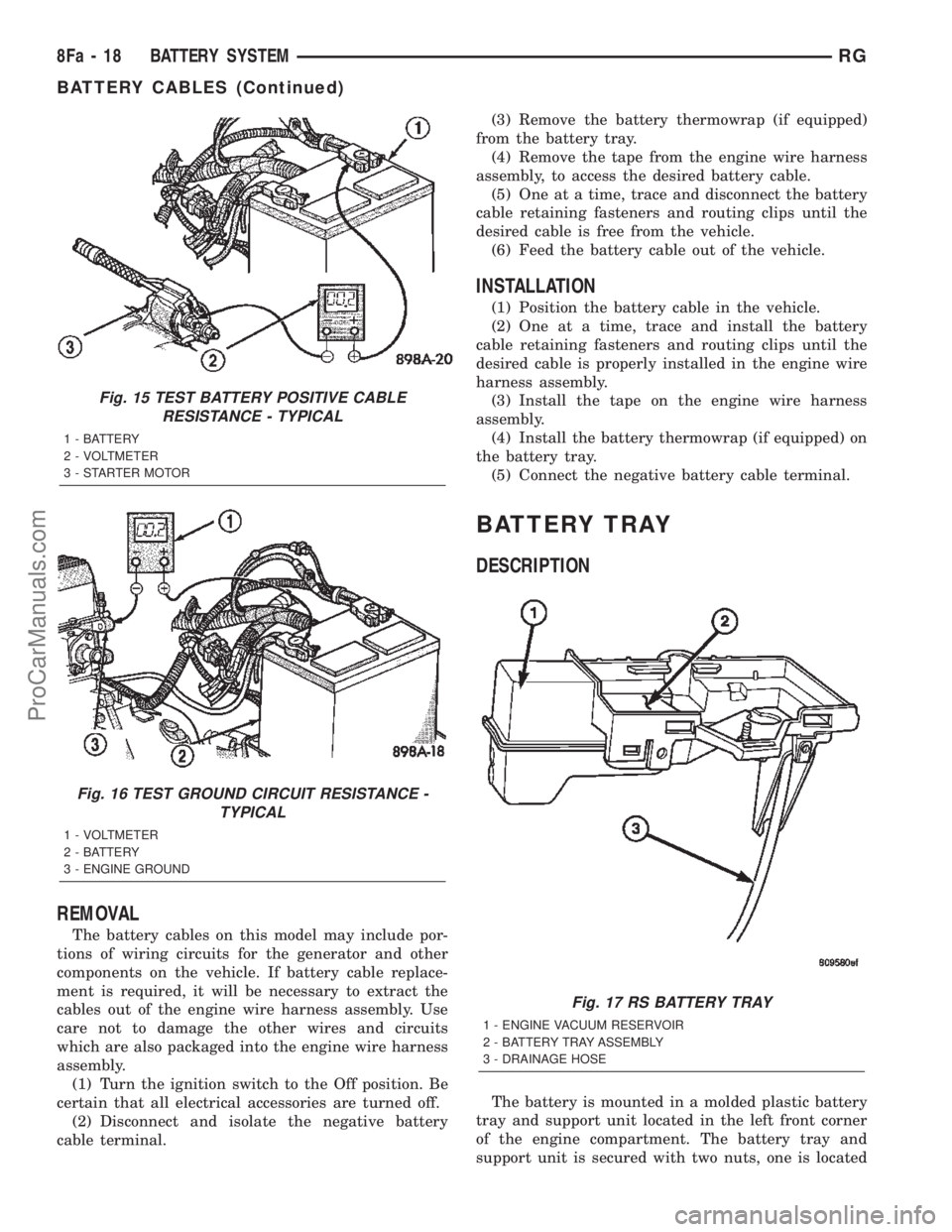
The battery is mounted in a molded plastic battery
tray and support unit located in the left front corner
of the engine compartment. The battery tray and
support unit is secured with two nuts, one is located
Fig. 15 TEST BATTERY POSITIVE CABLE
RESISTANCE - TYPICAL
1 - BATTERY
2 - VOLTMETER
3 - STARTER MOTOR
Fig. 16 TEST GROUND CIRCUIT RESISTANCE -
TYPICAL
1 - VOLTMETER
2 - BATTERY
3 - ENGINE GROUND
Fig. 17 RS BATTERY TRAY
1 - ENGINE VACUUM RESERVOIR
2 - BATTERY TRAY ASSEMBLY
3 - DRAINAGE HOSE
8Fa - 18 BATTERY SYSTEMRG
BATTERY CABLES (Continued)
ProCarManuals.com
Page 430 of 2399
directly under the battery and the other is located on
the right side of the tray which also serves as a cool-
ant bottle neck retaining bolt. An additional bolt is
located directly under the battery.
The battery tray and support unit also includes a
engine vacuum reservoir, located in the rear of the
unit (Fig. 17). And a drainage hose, located in the
front of the unit (Fig. 17).
OPERATION
The battery tray provides a secure mounting loca-
tion and supports the battery. The battery tray also
provides the anchor point for the battery holddown
hardware. The battery tray and the battery hold-
down hardware combine to secure and stabilize the
battery in the engine compartment, which prevents
battery movement during vehicle operation. Unre-
strained battery movement during vehicle operation
could result in damage to the vehicle, the battery, or
both.
The battery tray used on this model also includes a
engine vacuum reservoir and drainage hose. The vac-
uum reservoir provides a storage container for engine
vacuum. Refer to the engine section of the service
manual for more engine vacuum information. The
drainage hose provides means for any liquid that
might collect in the bottom of the battery tray to
drain under the vehicle.
REMOVAL
(1) Disconnect and isolate the negative battery
cable.
(2) Remove the battery from the vehicle. Refer to
the procedure in this section.
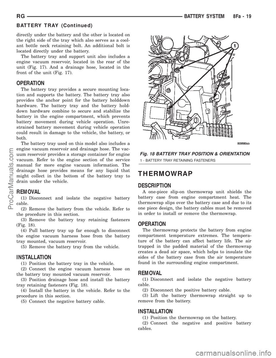
(3) Remove the battery tray retaining fasteners
(Fig. 18).
(4) Pull battery tray up far enough to disconnect
the engine vacuum harness hose from the battery
tray mounted, vacuum reservoir.
(5) Remove the battery tray from the vehicle.
INSTALLATION
(1) Position the battery tray in the vehicle.
(2) Connect the engine vacuum harness hose on
the battery tray mounted vacuum reservoir.
(3) Position drainage hose and install the battery
tray retaining fasteners (Fig. 18).
(4) Install the battery in the vehicle. Refer to the
procedure in this section.
(5) Connect the negative battery cable.
THERMOWRAP
DESCRIPTION
A one-piece slip-on thermowrap unit shields the
battery case from engine compartment heat. The
thermowrap slips over the battery case and due to its
one piece design, the battery cables must be removed
in order to install or remove the thermowrap.
OPERATION
The thermowrap protects the battery from engine
compartment temperature extremes. The tempera-
ture of the battery can affect battery life. The air
trapped in the padded material of the thermowrap
creates a dead air space, which helps to insulate the
sides of the battery case from the air temperature
found in the surrounding engine compartment.
REMOVAL
(1) Disconnect and isolate the negative battery
cable.
(2) Disconnect the positive battery cable.
(3) Lift the battery thermowrap straight up to
remove from the battery.
INSTALLATION
(1) Position the thermowrap on the battery.
(2) Connect the negative and positive battery
cables.
Fig. 18 BATTERY TRAY POSITION & ORIENTATION
1 - BATTERY TRAY RETAINING FASTENERS
RGBATTERY SYSTEM8Fa-19
BATTERY TRAY (Continued)
ProCarManuals.com
Page 431 of 2399
CHARGING
TABLE OF CONTENTS
page page
CHARGING
DESCRIPTION - CHARGING SYSTEM.......20
OPERATION - CHARGING SYSTEM.........20
DIAGNOSIS AND TESTING - ON-BOARD
DIAGNOSTIC SYSTEM.................21
SPECIFICATIONS
GENERATOR........................22
TORQUE............................22
SPECIAL TOOLS.......................22
BATTERY TEMPERATURE SENSOR
DESCRIPTION.........................23
OPERATION...........................23
REMOVAL.............................23
GENERATOR
DESCRIPTION.........................23
OPERATION...........................23
REMOVAL
REMOVAL - 2.4L......................23REMOVAL - 2.5L......................24
REMOVAL - 3.3/3.8L...................25
REMOVAL - 3.5L......................26
INSTALLATION
INSTALLATION - 2.4L..................27
INSTALLATION - 2.5L..................28
INSTALLATION - 3.3/3.8L................28
INSTALLATION - 3.5L..................28
GENERATOR DECOUPLER PULLEY
DESCRIPTION.........................28
OPERATION...........................28
DIAGNOSIS AND TESTING - GENERATOR
DECOUPLER PULLEY..................29
REMOVAL.............................29
INSTALLATION.........................30
VOLTAGE REGULATOR
DESCRIPTION.........................30
OPERATION...........................30
CHARGING
DESCRIPTION - CHARGING SYSTEM
The charging system consists of:
²Generator
²Decoupler Pulley (If equipped)
²Electronic Voltage Regulator (EVR) circuitry
within the Powertrain Control Module (PCM)
²Ignition switch (refer to the Ignition System sec-
tion for information)
²Battery (refer to the Battery section for informa-
tion)
²Inlet Air Temperature (calculated battery tem-
perature)
²Voltmeter (refer to the Instrument Cluster sec-
tion for information if equipped)
²Wiring harness and connections (refer to the
Wiring section for information)
²Accessory drive belt (refer to the Cooling section
for more information)
OPERATION - CHARGING SYSTEM
The charging system is turned on and off with the
ignition switch. The system is on when the engine is
running and the ASD relay is energized. The ASD
relay is energized when the PCM grounds the ASD
control circuit. This voltage is connected through the
PCM or IPM (intelligent power module) (if equipped)and supplied to one of the generator field terminals
(Gen. Source +) at the back of the generator.
The generator is driven by the engine through a
serpentine belt and pulley or decoupler pulley
arrangement.
The amount of DC current produced by the gener-
ator is controlled by the EVR (field control) circuitry
contained within the PCM. This circuitry is con-
nected in series with the second rotor field terminal
and ground.
An Inlet air temperature sensor is used to calcu-
late the temperature near the battery. This tempera-
ture data, along with data from monitored line
voltage (battery voltage sense circuit), is used by the
PCM to vary the battery charging rate. This is done
by cycling the ground path to control the strength of
the rotor magnetic field. The PCM then compensates
and regulates generator current output accordingly
to maintain system voltage at the targeted system
voltage based on battery temperature.
All vehicles are equipped with On-Board Diagnos-
tics (OBD). All OBD-sensed systems, including EVR
(field control) circuitry, are monitored by the PCM.
Each monitored circuit is assigned a Diagnostic Trou-
ble Code (DTC). The PCM will store a DTC in elec-
tronic memory for certain failures it detects and
illuminate the (MIL) lamp. Refer to On-Board Diag-
nostics in the Electronic Control Modules(Refer to 8 -
ELECTRICAL/ELECTRONIC CONTROL MOD-
8Fa - 20 CHARGINGRG
ProCarManuals.com
Page 432 of 2399
ULES/POWERTRAIN CONTROL MODULE -
DESCRIPTION) section for more DTC information.
The Check Gauges Lamp (if equipped) or Battery
Lamp monitors:charging system voltage,engine
coolant temperature and engine oil pressure. If an
extreme condition is indicated, the lamp will be illu-
minated. The signal to activate the lamp is sent via
the PCI bus circuits. The lamp is located on the
instrument panel. Refer to the Instrument Cluster
section for additional information.
The PCM uses the inlet air temperature sensor to
control the charge system voltage. This temperature,
along with data from monitored line voltage, is used
by the PCM to vary the battery charging rate. The
system voltage is higher at cold temperatures and is
gradually reduced as the calculated battery tempera-
ture increases.
The ambient temperature sensor is used to control
the battery voltage based upon ambient temperature
(approximation of battery temperature). The PCM
maintains the optimal output of the generator by
monitoring battery voltage and controlling it to a
range of 13.5 - 14.7 volts based on battery tempera-
ture.
DIAGNOSIS AND TESTING - ON-BOARD
DIAGNOSTIC SYSTEM
The Powertrain Control Module (PCM) monitors
critical input and output circuits of the charging sys-
tem, making sure they are operational. A Diagnostic
Trouble Code (DTC) is assigned to each input and
output circuit monitored by the OBD system. Some
circuits are checked continuously and some are
checked only under certain conditions.
If the OBD system senses that a monitored circuit
is bad, it will put a DTC into electronic memory. The
DTC will stay in electronic memory as long as the
circuit continues to be bad. The PCM is programmed
to clear the memory after 50 engine starts if the
problem does not occur again.
DIAGNOSTIC TROUBLE CODES
A DTC description can be read using the DRBIIIt
scan tool. Refer to the appropriate Powertrain Diag-
nostic Procedures manual for information.
A DTC does not identify which component in a cir-
cuit is bad. Thus, a DTC should be treated as a
symptom, not as the cause for the problem. In some
cases, because of the design of the diagnostic test
procedure, a DTC can be the reason for another DTC
to be set. Therefore, it is important that the test pro-
cedures be followed in sequence, to understand what
caused a DTC to be set.ERASING DIAGNOSTIC TROUBLE CODES
The DRBIIItScan Tool must be used to erase a
DTC.
The following procedures may be used to diagnose
the charging system if:
²the check gauges lamp or battery lamp is illumi-
nated with the engine running
²the voltmeter (if equipped) does not register
properly
²an undercharged or overcharged battery condi-
tion occurs.
Remember that an undercharged battery is often
caused by:
²accessories being left on with the engine not
running
²a faulty or improperly adjusted switch that
allows a lamp to stay on. Refer to Ignition-Off Draw
Test (Refer to 8 - ELECTRICAL/BATTERY SYSTEM/
BATTERY - STANDARD PROCEDURE)
INSPECTION
The Powertrain Control Module (PCM) monitors
critical input and output circuits of the charging sys-
tem, making sure they are operational. A Diagnostic
Trouble Code (DTC) is assigned to each input and
output circuit monitored by the On-Board Diagnostic
(OBD) system. Some charging system circuits are
checked continuously, and some are checked only
under certain conditions.
Refer to Diagnostic Trouble Codes in; Powertrain
Control Module; Electronic Control Modules for more
DTC information. This will include a complete list of
DTC's including DTC's for the charging system.
To perform a complete test of the charging system,
refer to the appropriate Powertrain Diagnostic Proce-
dures service manual and the DRBIIItscan tool.
Perform the following inspections before attaching
the scan tool.
(1) Inspect the battery condition. Refer to the Bat-
tery section (Refer to 8 - ELECTRICAL/BATTERY
SYSTEM - DIAGNOSIS AND TESTING) for proce-
dures.
(2) Inspect condition of battery cable terminals,
battery posts, connections at engine block, starter
solenoid and relay. They should be clean and tight.
Repair as required.
(3) Inspect all fuses in both the fuseblock and
Power Distribution Center (PDC) for tightness in
receptacles. They should be properly installed and
tight. Repair or replace as required.
(4) Inspect generator mounting bolts for tightness.
Replace or tighten bolts if required. Refer to the Gen-
erator Removal/Installation section of this group for
torque specifications (Refer to 8 - ELECTRICAL/
CHARGING - SPECIFICATIONS).
RGCHARGING8Fa-21
CHARGING (Continued)
ProCarManuals.com
Page 433 of 2399

(5) Inspect generator drive belt condition and ten-
sion. Tighten or replace belt as required. Refer to
Belt Tension Specifications(Refer to 7 - COOLING/
ACCESSORY DRIVE - SPECIFICATIONS).
(6) Inspect decoupler pulley (if equipped). Ensure
decoupler pulley is driving the alternator rotor.
(7) Inspect automatic belt tensioner (if equipped).
Refer to the Cooling System for more information.
(8) Inspect generator electrical connections at gen-
erator field, battery output, and ground terminal (if
equipped). Also check generator ground wire connec-
tion at engine (if equipped). They should all be clean
and tight. Repair as required.SPECIFICATIONS
GENERATOR
Type Engine Minimun Test
Amperage
Denso 2.4 L 125 Amp
Denso 3.3/3.8L 135 Amp or 145
Amp
Test Specification:
1. Engine RPM : 2500 RPM 20 RPM
2. Voltage Output : 14.0 V 0.5 V
3. Field Current : 5 amps 0.1 amps
Part number is located on the side of the generator.
TORQUE
DESCRIPTION N´m Ft. Lbs. In. Lbs.
Battery Hold Down Clamp
Bolt20 14.7 180
Generator B+ Nut 12.4 9.2 110
Battery Terminal Nut 4 35
Generator Mounting Bolt
2.4L28.2 20.8 250
Generator Mounting Bolts
3.3/3.8L54.2 40
Starter Solenoid Battery
Nut 3.3/3.8L11.3 8.3 100
Generator Decoupler 109.8 81
SPECIAL TOOLS
GENERATOR DECOUPLER 8433
8Fa - 22 CHARGINGRG
CHARGING (Continued)
ProCarManuals.com
Page 434 of 2399

BATTERY TEMPERATURE
SENSOR
DESCRIPTION
The PCM incorporates a Battery Temperature Sen-
sor (BTS) on its circuit board.
OPERATION
The PCM uses the temperature of the battery area
to control the charge system voltage. This tempera-
ture, along with data from monitored line voltage, is
used by the PCM to vary the battery charging rate.
The system voltage is higher at cold temperatures
and is gradually reduced as temperature around the
battery increases.
The ambient temperature sensor is used to control
the battery voltage based upon ambient temperature
(approximation of battery temperature). The PCM
maintains the optimal output of the generator by
monitoring battery voltage and controlling it to a
range of 13.5 - 14.7 volts based on battery tempera-
ture.
The battery temperature sensor is also used for
OBD II diagnostics. Certain faults and OBD II mon-
itors are either enabled or disabled depending upon
the battery temperature sensor input (example: dis-
able purge and EGR, enable LDP). Most OBD II
monitors are disabled below 20ÉF.
REMOVAL
The battery temperature sensor is not serviced sep-
arately. If replacement is necessary, the PCM must
be replaced.
GENERATOR
DESCRIPTION
The generator is belt-driven by the engine. It is
serviced only as a complete assembly. The generator
produces DC voltage at the B+ terminal. If the gen-
erator is failed, the generator assembly subcompo-
nents (generator and decoupler pulley) must be
inspected for individual failure and replaced accord-
ingly.
OPERATION
As the energized rotor begins to rotate within the
generator, the spinning magnetic field induces a cur-
rent into the windings of the stator coil. Once the
generator begins producing sufficient current, it also
provides the current needed to energize the rotor.
The Y type stator winding connections deliver the
induced AC current to 3 positive and 3 negative
diodes for rectification. From the diodes, rectified DC
current is delivered to the vehicles electrical system
through the generator, battery, and ground terminals.
Excessive or abnormal noise emitting from the gen-
erator may be caused by:
²Worn, loose or defective bearings
²Loose or defective drive pulley (2.4L) or decou-
pler (3.3/3.8L)
²Incorrect, worn, damaged or misadjusted drive
belt
²Loose mounting bolts
²Misaligned drive pulley
²Defective stator or diode
²Damaged internal fins
REMOVAL
REMOVAL - 2.4L
(1) Release hood latch and open hood.
(2) Disconnect battery negative cable.
(3) Disconnect the Inlet Air Temperature sensor.
(4) Remove the Air Box, refer to the Engine/Air
Cleaner for more information.
(5) Remove the EVAP Purge solenoid from its
bracket and reposition.
(6) Disconnect the push-in field wire connector
from back of generator.
(7) Remove nut holding B+ wire terminal to back
of generator.
(8) Separate B+ terminal from generator.
(9) Remove accessory drive belt, refer to the Cool-
ing System section for proper procedures.
(10) Remove the generator.
RGCHARGING8Fa-23
ProCarManuals.com