engine mount CHRYSLER CARAVAN 2002 Owners Manual
[x] Cancel search | Manufacturer: CHRYSLER, Model Year: 2002, Model line: CARAVAN, Model: CHRYSLER CARAVAN 2002Pages: 2399, PDF Size: 57.96 MB
Page 483 of 2399
INSTALLATION - 3.3/3.8L
(1) Install coil over studs on bracket.
(2) Install 2 bolts to ignition coil.
(3) Install 2 nuts to the ignition coil studs. Tighten
nuts and bolts.
(4) Connect the electrical connector to the ignition
coil.
(5) Install the ignition cables to the ignition coil.
(6) Reposition the Power steering reservoir. Slide
bracket over the mounting stud (Fig. 11).
(7) Install 2 bolts to the Power steering reservoir
to intake manifold.
(8) Tighten the lower nut to stud on ignition coil
bracket.
(9) Install the throttle and speed control cables to
clip.
(10) Connect the negative battery cable.
KNOCK SENSOR
DESCRIPTION
The knock sensor threads into the cylinder block.
The knock sensor is designed to detect engine vibra-
tion that is caused by detonation.
OPERATION
When the knock sensor detects a knock in one of
the cylinders, it sends an input signal to the PCM. In
response, the PCM retards ignition timing for all cyl-
inders by a scheduled amount.
Knock sensors contain a piezoelectric material
which constantly vibrates and sends an input voltage
(signal) to the PCM while the engine operates. As the
intensity of the crystal's vibration increases, the
knock sensor output voltage also increases.
The voltage signal produced by the knock sensor
increases with the amplitude of vibration. The PCM
receives as an input the knock sensor voltage signal.
If the signal rises above a predetermined level, the
PCM will store that value in memory and retard
ignition timing to reduce engine knock. If the knock
sensor voltage exceeds a preset value, the PCM
retards ignition timing for all cylinders. It is not a
selective cylinder retard.
The PCM ignores knock sensor input during engine
idle conditions. Once the engine speed exceeds a
specified value, knock retard is allowed.
Knock retard uses its own short term and long
term memory program.
Long term memory stores previous detonation
information in its battery-backed RAM. The maxi-
mum authority that long term memory has over tim-
ing retard can be calibrated.
Short term memory is allowed to retard timing up
to a preset amount under all operating conditions (aslong as rpm is above the minimum rpm) except WOT.
The PCM, using short term memory, can respond
quickly to retard timing when engine knock is
detected. Short term memory is lost any time the
ignition key is turned off.
NOTE: Over or under tightening affects knock sen-
sor performance, possibly causing improper spark
control.
REMOVAL
REMOVAL - 2.4L
The knock sensor threads into the side of the cyl-
inder block in front of the starter (Fig. 12).
(1) Disconnect electrical connector from knock sen-
sor.
(2) Use a crow foot socket to remove the knock
sensors.
REMOVAL - 3.8L
The knock sensor threads into the side of the cyl-
inder block in the rear.
(1) Disconnect the negative battery cable.
(2) Raise vehicle and support.
(3) On All Wheel Drive vehicles remove the PTU
(Power Transfer Unit), refer to the Transmission sec-
tion for more information.
(4) Disconnect electrical connector from knock sen-
sor.
(5) Use a crow foot socket to remove the knock
sensor.
INSTALLATION
INSTALLATION - 2.4L
The knock sensor threads into the side of the cyl-
inder block in front of the starter (Fig. 12).
(1) Install knock sensor. Tighten knock sensor to
10 N´m (7 ft. lbs.) torque.Over or under tighten-
ing effects knock sensor performance, possibly
causing improper spark control.
(2) Attach electrical connector to knock sensor.
INSTALLATION - 3.8L
The knock sensor threads into the side of the cyl-
inder block in the rear.
(1) Install knock sensor. Tighten knock sensor to
10 N´m (7 ft. lbs.) torque.Over or under tighten-
ing effects knock sensor performance, possibly
causing improper spark control.
(2) Attach electrical connector to knock sensor.
8I - 8 IGNITION CONTROLRS
IGNITION COIL (Continued)
ProCarManuals.com
Page 487 of 2399
The Glow Plug lamp is tied to this circuit. Lamp
operation is also controlled by the ECM.
With a cold engine, the glow plug relays and glow
plugs may be activated for a maximum time of 200
seconds. Refer to the following Glow Plug Control
chart for a temperature/time comparison of the glow
plug relay operation.
In this chart, Pre-Heat and Post-Heat times are
mentioned. Pre-Heat is the amount of time the glow
plug relay control circuit is activated when the igni-
tion (key) is switched ON, without the engine run-
ning. Post-Heat is the amount of time the glow plug
relay control circuit is activated after the engine is
operated. The Glow Plug lamp will not be activated
during the post-heat cycle.
Engine
Coolant
Temperature
9Key ON9Wait-To
Start Lamp
9ON9
(Seconds)Pre-Heat
Cycle
(Glow
Plugs On
Seconds)Post-Heat
Cycle
(Seconds)
-30C 20 SEC. 35 SEC. 200 SEC.
-10C 8 SEC. 23 SEC. 180 SEC.
+10C 6 SEC. 21 SEC. 160 SEC.
+30C 5 SEC. 20 SEC. 140 SEC.
+40C 4 SEC. 19 SEC. 70 SEC.
+70C 1 SEC. 16 SEC. 20 SEC.
CAMSHAFT POSITION
SENSOR
DESCRIPTION
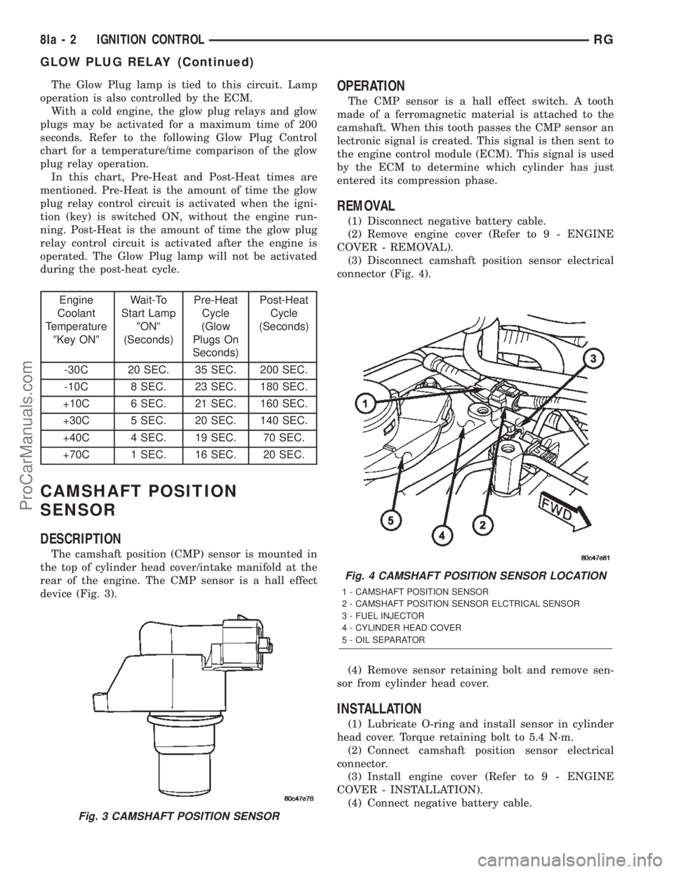
The camshaft position (CMP) sensor is mounted in
the top of cylinder head cover/intake manifold at the
rear of the engine. The CMP sensor is a hall effect
device (Fig. 3).
OPERATION
The CMP sensor is a hall effect switch. A tooth
made of a ferromagnetic material is attached to the
camshaft. When this tooth passes the CMP sensor an
lectronic signal is created. This signal is then sent to
the engine control module (ECM). This signal is used
by the ECM to determine which cylinder has just
entered its compression phase.
REMOVAL
(1) Disconnect negative battery cable.
(2) Remove engine cover (Refer to 9 - ENGINE
COVER - REMOVAL).
(3) Disconnect camshaft position sensor electrical
connector (Fig. 4).
(4) Remove sensor retaining bolt and remove sen-
sor from cylinder head cover.
INSTALLATION
(1) Lubricate O-ring and install sensor in cylinder
head cover. Torque retaining bolt to 5.4 N´m.
(2) Connect camshaft position sensor electrical
connector.
(3) Install engine cover (Refer to 9 - ENGINE
COVER - INSTALLATION).
(4) Connect negative battery cable.
Fig. 3 CAMSHAFT POSITION SENSOR
Fig. 4 CAMSHAFT POSITION SENSOR LOCATION
1 - CAMSHAFT POSITION SENSOR
2 - CAMSHAFT POSITION SENSOR ELCTRICAL SENSOR
3 - FUEL INJECTOR
4 - CYLINDER HEAD COVER
5 - OIL SEPARATOR
8Ia - 2 IGNITION CONTROLRG
GLOW PLUG RELAY (Continued)
ProCarManuals.com
Page 508 of 2399
(3) Install the retaining screws.
(4) Reconnect the battery negative cable.
FOG LAMP
DIAGNOSIS AND TESTING - FOG LAMP
When a vehicle experiences problems with the fog
lamp system, verify the condition of the battery con-
nections, fuses, charging system, fog lamp bulbs, wire
connectors, relay, high beam switch, and headlamp
switch. Refer to the appropriate wiring information.
Each vehicle is equipped with various lamp assem-
blies. A good ground is necessary for proper lighting
operation. Grounding is provided by the lamp socket
when it comes in contact with the metal body, or
through a separate ground wire.
When changing lamp bulbs check the socket for
corrosion. If corrosion is present, clean it with a wire
brush.
When it is necessary to remove components to ser-
vice another, it should not be necessary to apply
excessive force or bend a component to remove it.
Before damaging a trim component, verify hidden
fasteners or captured edges are not holding the com-
ponent in place.
FOG LAMP DIAGNOSIS
CONDITION POSSIBLE CAUSES CORRECTION
FOG LAMPS ARE DIM
WITH ENGINE IDLING
OR IGNITION TURNED
OFF.1. Loose or corroded battery
cables.1. Clean and secure battery cable clamps and
posts.
2. Loose or worn generator drive
belt.2. Adjust or replace generator drive belt.
3. Charging system output too low. 3. Test and repair charging system. Refer to
Electrical, Charging,
4. Battery has insufficient charge. 4. Test battery state-of-charge. Refer to
Electrical, Battery System.
5. Battery is sulfated or shorted. 5. Load test battery. Refer to Electrical, Battery
System.
6. Poor lighting circuit Z349/Z248
ground.6. Test for voltage drop across Z349/248
ground locations. Refer to Electrical, Wiring
Information.
FOG LAMP BULBS
BURN OUT
FREQUENTLY1. Charging system output too
high.1. Test and repair charging system. Refer to
Electrical, Charging.
2. Loose or corroded terminals or
splices in circuit.2. Inspect and repair all connectors and splices.
Refer to Electrical, Wiring Information.
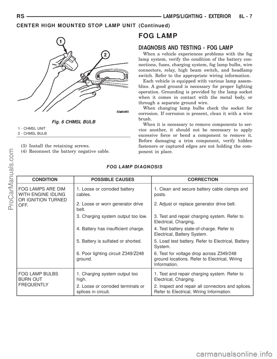
Fig. 6 CHMSL BULB
1 - CHMSL UNIT
2 - CHMSL BULB
RSLAMPS/LIGHTING - EXTERIOR8L-7
CENTER HIGH MOUNTED STOP LAMP UNIT (Continued)
ProCarManuals.com
Page 539 of 2399
ules push buttons located just rearward of the dis-
play screen in the overhead console. The three
universal transmitter push buttons are identified
with one, two or three light indicators so that they be
easily identified by sight or by feel.
Each of the three universal transmitter push but-
tons controls an independent radio transmitter chan-
nel. Each of these three channels can be trained to
transmit a different radio frequency signal for the
remote operation of garage door openers, motorized
gate openers, home or office lighting, security sys-
tems or just about any other device that can be
equipped with a radio receiver in the 286 to 399
MegaHertz (MHz) frequency range for remote opera-
tion. The universal transmitter is capable of operat-
ing systems using either rolling code or non-rolling
code technology.
The electronics module displays messages and a
small house-shaped icon with one, two or three dots
corresponding to the three transmitter buttons to
indicate the status of the universal transmitter. The
EVIC messages are:
²Cleared Channels- Indicates that all of the
transmitter codes stored in the universal transmitter
have been successfully cleared.
²Training- Indicates that the universal trans-
mitter is in its transmitter learning mode.
²Trained- Indicates that the universal transmit-
ter has successfully acquired a new transmitter code.
²Transmit- Indicates that a trained universal
transmitter button has been depressed and that the
universal transmitter is transmitting.
The universal transmitter cannot be repaired, and
is available for service only as a unit with the EVIC
or CMTC modules. If any of these components is
faulty or damaged, the complete EVIC or CMTC
module must be replaced.
OPERATION
The universal transmitter operates on a non-
switched source of battery current so the unit will
remain functional, regardless of the ignition switch
position. For more information on the features, pro-
gramming procedures and operation of the universal
transmitter, see the owner's manual in the vehicle
glove box.
DIAGNOSIS AND TESTING - UNIVERSAL
TRANSMITTER
If the universal transmitter is inoperative, but the
Electronic Vehicle Information Center (EVIC) or
Compass Mini-Trip Computer is operating normally,
see the owner's manual in the vehicle glove box for
instructions on training the universal transmitter.
Retrain the universal transmitter with a known good
transmitter as instructed in the owner's manual andtest the universal transmitter operation again. If the
unit is still inoperative, replace the faulty universal
transmitter and EVIC/CMTC module as a unit. If
both the universal transmitter and the EVIC/CMTC
module are inoperative, refer toOverhead Console
Diagnosis and Testingearlier in this group for fur-
ther diagnosis. For complete circuit diagrams, refer
toOverhead Consolein Wiring Diagrams.
AMBIENT TEMP SENSOR
DESCRIPTION
Ambient air temperature is monitored by the over-
head console through ambient temperature messages
received from the Front Control Module (FCM) over
the Programmable Communications Interface (PCI)
J1850 data bus circuit. The FCM receives a hard
wired input from the ambient temperature sensor.
The ambient temperature sensor is a variable resis-
tor mounted to a bracket that is secured with a screw
to the right side of the headlamp mounting module
grille opening, behind the radiator grille and in front
of the engine compartment.
Refer toFront Control Modulein Electronic
Control Modules. For complete circuit diagrams, refer
to the appropriate wiring information. The ambient
temperature sensor cannot be adjusted or repaired
and, if faulty or damaged, it must be replaced.
OPERATION
The ambient temperature sensor is a variable
resistor that operates on a five-volt reference signal
sent to it by the Front Control Module. The resis-
tance in the sensor changes as temperature changes,
changing the temperature sensor signal circuit volt-
age to the Front Control Module. Based upon the
resistance in the sensor, the Front Control Module
senses a specific voltage on the temperature sensor
signal circuit, which it is programmed to correspond
to a specific temperature. The Front Control Module
then sends the proper ambient temperature mes-
sages to the EVIC, CMTC over the PCI J1850 data
bus.
The thermometer function is supported by the
ambient temperature sensor, a wiring circuit, the
Front Control Module, the Programmable Communi-
cations Interface (PCI) data bus, and a portion of the
Electronics module. If any portion of the ambient
temperature sensor circuit fails, the Front Control
Module will self-diagnose the circuit.
The ambient temperature sensor circuit can also be
diagnosed by referring toDiagnosis and Testing -
Ambient Temperature Sensor, and Diagnosis
and Testing - Ambient Temperature Sensor Cir-
cuit. If the temperature sensor and circuit are con-
8M - 10 MESSAGE SYSTEMSRS
UNIVERSAL TRANSMITTER (Continued)
ProCarManuals.com
Page 631 of 2399
(2) Turn off ignition.
(3) Remove the air bag, refer to the restraint sec-
tion for more information.
(4) Remove the screw from bottom of the switch.
(5) Remove switch from steering wheel.
(6) Disconnect two-way electrical connector.
(7) Repeat for the other switch.
INSTALLATION
The speed control switches are mounted in the
steering wheel and wired through the clock spring
device under the airbag module.
WARNING: IF REMOVAL OF AIRBAG MODULE IS
NECESSARY, REFER TO THE RESTRAINT SYS-
TEMS SECTION FOR MORE INFORMATION.
(1) Connect two-way electrical connector.
(2) Install switch.
(3) Install screw for the switch.
(4) Repeat for the other switch.
(5) Install the air bag, refer to the restraint section
for more information.
(6) Install the negative battery cable.
VACUUM RESERVOIR
DESCRIPTION
The vacuum reservoir is located in the engine com-
partment. It is made of plastic.
OPERATION
The reservoir stores engine vacuum. Manifold vac-
uum is supplied from the brake booster check valve.
The speed control vacuum supply hose has a check
valve at the source (brake booster) to maintain the
highest available vacuum level in the servo, reservoir
and vacuum hoses. When engine vacuum drops, as in
climbing a grade while driving, the reservoir supplies
the vacuum needed to maintain proper speed control
operation. The vacuum reservoir cannot be repaired
and must be replaced if faulty.
REMOVAL
(1) Release hood latch and open hood.
(2) Disconnect the negative battery cable.
(3) Disconnect the vacuum line to the battery tray/
vacuum reservoir.
(4) Remove battery tray/vacuum reservoir, refer to
the Battery section for more information.
INSTALLATION
(1) Install battery tray/vacuum reservoir, refer to
the Battery section for more information.
(2) Connect vacuum line that leads to the battery
tray/vacuum reservoir.
(3) Connect the negative battery cable.
8P - 6 SPEED CONTROLRS
SWITCH (Continued)
ProCarManuals.com
Page 632 of 2399

VEHICLE THEFT SECURITY
TABLE OF CONTENTS
page page
VEHICLE THEFT SECURITY
DESCRIPTION..........................1
OPERATION............................1
DIAGNOSIS AND TESTING
DIAGNOSIS AND TESTING - SENTRY KEY
IMMOBILIZER SYSTEM..................3
DIAGNOSIS AND TESTING - VEHICLE
THEFT SECURITY SYSTEM..............3
HOOD AJAR SWITCH
REMOVAL.............................3INSTALLATION..........................3
TRANSPONDER KEY
DESCRIPTION..........................3
OPERATION............................3
STANDARD PROCEDURE - TRANSPONDER
PROGRAMMING.......................4
VTSS/SKIS INDICATOR LAMP
DESCRIPTION..........................5
OPERATION............................5
VEHICLE THEFT SECURITY
DESCRIPTION
VEHICLE THEFT SECURITY SYSTEM
The Vehicle Theft Security System (VTSS) is
designed to protect against whole vehicle theft. The
system monitors vehicle doors, hood, liftgate, and
ignition action for unauthorized operation. The alarm
activates:
²Sounding of the horn
²Flashing of the park and tail lamps
²Flashing of the headlamps
²An engine kill feature (without SKIS)
SENTRY KEY IMMOBILIZER SYSTEM
The Sentry Key Immobilizer System (SKIS) is
available as a factory-installed option on this vehicle.
It is designed to provide passive protection against
unauthorized vehicle use by disabling the engine,
after two (2) seconds of running, whenever an invalid
key is used to start the vehicle. The SKIS is active
whenever the ignition is on and does not require any
customer intervention. The primary components of
the system are the Sentry Key Immobilizer Module
(SKIM), Sentry Key (ignition key w/ a transponder
molded into the head), indicator light, Body Control
Module (BCM), and the Powertrain Control Module
(PCM). The SKIM is mounted to the steering column
with the molded, integral antenna mounted on the
ignition housing. The indicator light, is located in the
message center.
OPERATION
VEHICLE THEFT SECURITY SYSTEM
Upon failure of proper SKIM communication to the
PCM, the PCM will shut off fuel after two seconds of
run time. The engine will not re-crank on the key
cycle that the failure occurred, a full key down
sequence must be performed for the engine to crank
again. After six consecutive fuel shut-offs, the engine
will no longer crank on subsequent key cycles. The
failure must be corrected and a valid communication
process between the SKIM and the PCM must occur
for the engine to crank and start again.
The electronics for the VTSS are part of the Body
Control Module (BCM). The system is armed when
the vehicle is locked using the:
²Power door lock switches (with any door ajar)
²Remote Keyless Entry transmitter.
²Door Cylinder Lock Switches.
For vehicles equipped with SKIS, the doors do not
have to be locked to enable the fuel shut off feature.
After the vehicle is locked and the last door is
closed, the set LED indicator in the top cover will
flash quickly for 16 seconds, indicating that arming
is in progress. If no monitored systems are activated
during this period, the system will arm. The LED
will extinguish unless the liftgate is open. If the lift-
gate is open, the LED will flash at a slower rate.
This indicates that the system is armed. If fault is
detected on any key cylinder input, the indicator
LED will remain solid during the arming process,
although the system will still arm. If the indicator
LED does not illuminate at all upon door closing it
indicates that the system is not arming.
RSVEHICLE THEFT SECURITY8Q-1
ProCarManuals.com
Page 646 of 2399

FRONT WASHER PUMP
MOTOR
REMOVAL
(1) Disconnect and isolate the battery negative
cable.
(2) Remove the engine fresh air housing inside the
engine compartment (Refer to 9 - ENGINE/AIR
INTAKE SYSTEM/AIR CLEANER HOUSING -
REMOVAL).
(3) Disconnect the washer hose at the in-line con-
nector forward of the cowl grille so that the in-line
connector remains with the washer hose from the
fresh air plenum.
(4) Disconnect the washer hose from the hose clip
located on the front fender side shield.
(5) Remove the filler tube screw.
(6) Hoist and support vehicle on hoist or jack
stands.
(7) Remove the right front wheel and tire assembly
(Refer to 22 - TIRES/WHEELS - REMOVAL).
(8) Disconnect the left right front wheelhouse
splash shield and move aside (Refer to 23 - BODY/
EXTERIOR/WHEELHOUSE SPLASH SHIELD -
REMOVAL).
(9) Drain washer fluid from the reservoir and into
a suitable clean container. This can be done by dis-
connecting the windshield washer hose from the
front (outboard) washer pump and allowing the
washer fluid to drain into a container through a tem-
porary jumper hose connected to the front washer
pump.
(10) Disconnect the electrical body harness connec-
tors to the washer pump motors and the fluid level
sensor. Slide the red lock on the connector to the
release position, then, depress the black tab and pull
the connector off the pump or sensor.
(11) Remove the two reservoir mounting screws.
(12) Disconnect the reservoir from the body mount
by raising the reservoir upward slightly and then
down so that the reservoir filler neck and front
washer hose pull through the opening in the front
fender side shield.
(13) Remove pump from reservoir by pulling pump
upper retention tab away from reservoir cavity and
then lifting pump up from mounting grommet. Do
not damage reservoir/pump sealing surface or punc-
ture reservoir during removal.
(14) Remove pump grommet and discard.
INSTALLATION
(1) Use new grommet when installing a new pump
assembly.
(2) Assure pump upper retention tab is pressed
into reservoir slot and that pump is rotated flatagainst the reservoir and that pump connector is fac-
ing up in the fully seated position. Assure the pump
is aligned to and fully seated in the reservoir cavity.
(3) Push filler neck and front washer hose through
the opening in the front fender side shield. Connect
the reservoir to the body mount by lowering the res-
ervoir down.
(4) Install the two reservoir mounting screws.
Torque screws to 8.5 - 11.3 N´m (75 - 100 in. lbs.).
(5) Connect the electrical body harness connectors
to the washer pump motors and the fluid level sen-
sor. Slide the red lock on the connector to the closed
or locked position.
(6) Assure that washer hose is properly routed to
prevent pinching and possible inoperative washers.
(7) Connect the left right front wheelhouse splash
shield and move aside (Refer to 23 - BODY/EXTERI-
OR/WHEELHOUSE SPLASH SHIELD - INSTALLA-
TION).
(8) Install the right front wheel and tire assembly
(Refer to 22 - TIRES/WHEELS - INSTALLATION).
(9) lower vehicle from hoist or jack stands.
(10) Install the filler tube screw. Torque screw to
8.5 - 11.3 N´m (75 - 100 in. lbs.).
(11) Connect the washer hose to the hose clip
located on the front fender side shield.
(12) Connect the washer hose at the in-line con-
nector forward of the cowl grille.
(13) Install the engine fresh air housing inside the
engine compartment (Refer to 9 - ENGINE/AIR
INTAKE SYSTEM/AIR CLEANER HOUSING -
INSTALLATION).
(14) Connect the battery negative cable.
(15) Verify system operation.
FRONT WIPER ARMS
STANDARD PROCEDURE - FRONT WIPER ARM
ALIGNMENT
(1) Verify wiper blade element condition and wiper
arm spring tension. Run wipers in low speed mode
while applying water to the windshield. Observe the
wiper blade that is chattering or skipping across the
windshield. If the wiper element is not rolling over
when the wiper direction reverses, align the wiper
arm. The extension bar portion of the wiper arm
must be twisted in the proper direction to allow the
wiper element to roll over when the direction
reverses.
(2) Place two small adjustable wrenches placed 50
mm (2 in.) apart on the wiper arm extension rod.
(3) Twist the extension rod slightly in the opposite
direction that the element is laying on the wind-
shield while holding the wrench closest to the pivot
stationary.
RSWIPERS/WASHERS8R-9
ProCarManuals.com
Page 651 of 2399

(9) Drain washer fluid from the reservoir and into
a suitable clean container. This can be done by dis-
connecting the windshield washer hose from the
front (outboard) washer pump and allowing the
washer fluid to drain into a container through a tem-
porary jumper hose connected to the front washer
pump.
(10) Disconnect the rear washer pump hose from
washer pump.
(11) Disconnect the high pressure headlamp
washer pump hose by pressing down firmly on latch
and pulling hose off.
(12) Disconnect the electrical body harness connec-
tors to the washer pump motors and the fluid level
sensor. Slide the red lock on the connector to the
release position, then, depress the black tab and pull
the connector off the pump or sensor.
(13) Remove the two reservoir mounting screws.
(14) Disconnect the reservoir from the body mount
by raising the reservoir upward slightly and then
down so that the reservoir filler neck and front
washer hose pull through the opening in the front
fender side shield.
(15) Remove pump from reservoir by pulling pump
up and away from reservoir cavity and out of mount-
ing grommet. Do not damage reservoir/pump sealing
surface or puncture reservoir during removal.
(16) Remove pump grommet and discard.
INSTALLATION
(1) Use new grommet when installing a new pump
assembly.
(2) Assure pump upper retention tab is pressed
into reservoir slot and assure the pump is aligned to
and fully seated in the reservoir cavity.
(3) Push filler neck and front washer hose through
the opening in the front fender side shield. Connect
the reservoir to the body mount by lowering the res-
ervoir down.
(4) Install the two reservoir mounting screws.
Torque screws to 8.5 - 11.3 N´m (75 - 100 in. lbs.).
(5) Connect the electrical body harness connectors
to the washer pump motors and the fluid level sen-
sor. Slide the red lock on the connector to the closed
or locked position.
(6) Connect front and rear washer pump hoses and
assure that they are properly routed to prevent
pinching and possible inoperative washers.
(7) Connect the high pressure headlamp washer
hose by firmly pushing hose onto inlet until a snap is
heard.
(8) Connect the left right front wheelhouse splash
shield and move aside (Refer to 23 - BODY/EXTERI-
OR/WHEELHOUSE SPLASH SHIELD - INSTALLA-
TION).(9) Install the right front wheel and tire assembly
(Refer to 22 - TIRES/WHEELS - INSTALLATION).
(10) lower vehicle from hoist or jack stands.
(11) Install the filler tube screw. Torque screw to
8.5 - 11.3 N´m (75 - 100 in. lbs.).
(12) Connect the washer hose to the hose clip
located on the front fender side shield.
(13) Connect the washer hose at the in-line con-
nector forward of the cowl grille.
(14) Install the engine fresh air housing inside the
engine compartment (Refer to 9 - ENGINE/AIR
INTAKE SYSTEM/AIR CLEANER HOUSING -
INSTALLATION).
(15) Connect the battery negative cable.
(16) Verify vehicle and system operation.
REAR WASHER PUMP MOTOR
REMOVAL
(1) Disconnect and isolate the battery negative
cable.
(2) Remove the engine fresh air housing inside the
engine compartment (Refer to 9 - ENGINE/AIR
INTAKE SYSTEM/AIR CLEANER HOUSING -
REMOVAL).
(3) Disconnect the washer hose at the in-line con-
nector forward of the cowl grille so that the in-line
connector remains with the washer hose from the
fresh air plenum.
(4) Disconnect the washer hose from the hose clip
located on the front fender side shield.
(5) Remove the filler tube screw.
(6) Hoist and support vehicle on hoist or jack
stands.
(7) Remove the right front wheel and tire assembly
(Refer to 22 - TIRES/WHEELS - REMOVAL).
(8) Disconnect the left right front wheelhouse
splash shield and move aside (Refer to 23 - BODY/
EXTERIOR/WHEELHOUSE SPLASH SHIELD -
REMOVAL).
(9) Drain washer fluid from the reservoir and into
a suitable clean container. This can be done by dis-
connecting the windshield washer hose from the
front (outboard) washer pump and allowing the
washer fluid to drain into a container through a tem-
porary jumper hose connected to the front washer
pump.
(10) Disconnect the electrical body harness connec-
tors to the washer pump motors and the fluid level
sensor. Slide the red lock on the connector to the
release position, then, depress the black tab and pull
the connector off the pump or sensor.
(11) Remove the two reservoir mounting screws.
8R - 14 WIPERS/WASHERSRS
HEADLAMP WASHER PUMP MOTOR - EXPORT (Continued)
ProCarManuals.com
Page 652 of 2399
(12) Disconnect the reservoir from the body mount
by raising the reservoir upward slightly and then
down so that the reservoir filler neck and front
washer hose pull through the opening in the front
fender side shield.
(13) Remove pump from reservoir by pulling pump
upper retention tab away from reservoir cavity and
then lifting pump up from mounting grommet. Do
not damage reservoir/pump sealing surface or punc-
ture reservoir during removal.
(14) Remove pump grommet and discard.
INSTALLATION
(1) Use new grommet when installing a new pump
assembly.
(2) Assure pump upper retention tab is pressed
into reservoir slot and that pump is rotated flat
against the reservoir and that pump connector is fac-
ing up in the fully seated position. Assure the pump
is aligned to and fully seated in the reservoir cavity.
(3) Push filler neck and front washer hose through
the opening in the front fender side shield. Connect
the reservoir to the body mount by lowering the res-
ervoir down.
(4) Install the two reservoir mounting screws.
Torque screws to 8.5 - 11.3 N´m (75 - 100 in. lbs.).
(5) Connect the electrical body harness connectors
to the washer pump motors and the fluid level sen-
sor. Slide the red lock on the connector to the closed
or locked position.
(6) Assure that washer hose is properly routed to
prevent pinching and possible inoperative washers.
(7) Connect the left right front wheelhouse splash
shield and move aside (Refer to 23 - BODY/EXTERI-
OR/WHEELHOUSE SPLASH SHIELD - INSTALLA-
TION).
(8) Install the right front wheel and tire assembly
(Refer to 22 - TIRES/WHEELS - INSTALLATION).
(9) lower vehicle from hoist or jack stands.
(10) Install the filler tube screw. Torque screw to
8.5 - 11.3 N´m (75 - 100 in. lbs.).
(11) Connect the washer hose to the hose clip
located on the front fender side shield.
(12) Connect the washer hose at the in-line con-
nector forward of the cowl grille.(13) Install the engine fresh air housing inside the
engine compartment (Refer to 9 - ENGINE/AIR
INTAKE SYSTEM/AIR CLEANER HOUSING -
INSTALLATION).
(14) Connect the battery negative cable.
(15) Verify system operation.
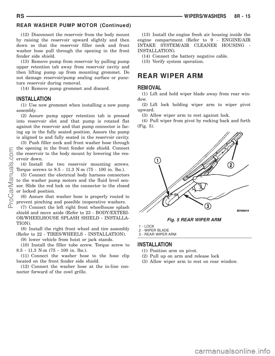
REAR WIPER ARM
REMOVAL
(1) Lift and hold wiper blade away from rear win-
dow.
(2) Lift lock holding wiper arm to wiper pivot
upward.
(3) Allow wiper arm to rest against lock.
(4) Pull wiper from pivot by rocking back and forth
(Fig. 5).
INSTALLATION
(1) Position arm on pivot.
(2) Pull up on arm and release lock
(3) Allow wiper arm to rest on rear window.
Fig. 5 REAR WIPER ARM
1 - LOCK
2 - WIPER BLADE
3 - REAR WIPER ARM
RSWIPERS/WASHERS8R-15
REAR WASHER PUMP MOTOR (Continued)
ProCarManuals.com
Page 654 of 2399

(6) Hoist and support vehicle on hoist or jack
stands.
(7) Remove the right front wheel and tire assembly
(Refer to 22 - TIRES/WHEELS - REMOVAL).
(8) Disconnect the left right front wheelhouse
splash shield and move aside (Refer to 23 - BODY/
EXTERIOR/WHEELHOUSE SPLASH SHIELD -
REMOVAL).
(9) Drain washer fluid from the reservoir and into
a suitable clean container. This can be done by dis-
connecting the windshield washer hose from the
front (outboard) washer pump and allowing the
washer fluid to drain into a container through a tem-
porary jumper hose connected to the front washer
pump.
(10) Disconnect the electrical body harness connec-
tors to the washer pump motors and the fluid level
sensor. Slide the red lock on the connector to the
release position, then, depress the black tab and pull
the connector off the pump or sensor.
(11) Remove the two reservoir mounting screws.
(12) Disconnect the reservoir from the body mount
by raising the reservoir upward slightly and then
down so that the reservoir filler neck and front
washer hose pull through the opening in the front
fender side shield.
(13) Remove the sensor from reservoir by using a
side foot to gently pry the sensor from the body of
the reservoir. Do not damage the reservoir/sensor
sealing surface or puncture reservoir during removal.
CAUTION: To avoid damage to the sensor, assure
the reservoir is in an upright position before remov-
ing the sensor from the reservoir. Do not rotate the
sensor during removal.
INSTALLATION
(1) Use a new grommet when installing a new sen-
sor assembly.
(2) Assure that the flat of the sensor is aligned
under the ridge of the reservoir and that the sensor
connector is facing down in the fully seated position.
This will allow for proper operation of the sensor
float switch.
(3) Push filler neck and front washer hose through
the opening in the front fender side shield. Connect
the reservoir to the body mount by lowering the res-
ervoir down.
(4) Install the two reservoir mounting screws.
Torque screws to 8.5 - 11.3 N´m (75 - 100 in. lbs.).(5) Connect the electrical body harness connectors
to the washer pump motors and the fluid level sen-
sor. Slide the red lock on the connector to the closed
or locked position.
(6) Assure that washer hose is properly routed to
prevent pinching and possible inoperative washers.
(7) Connect the left right front wheelhouse splash
shield and move aside (Refer to 23 - BODY/EXTERI-
OR/WHEELHOUSE SPLASH SHIELD - INSTALLA-
TION).
(8) Install the right front wheel and tire assembly
(Refer to 22 - TIRES/WHEELS - INSTALLATION).
(9) lower vehicle from hoist or jack stands.
(10) Install the filler tube screw. Torque screw to
8.5 - 11.3 N´m (75 - 100 in. lbs.).
(11) Connect the washer hose to the hose clip
located on the front fender side shield.
(12) Connect the washer hose at the in-line con-
nector forward of the cowl grille.
(13) Install the engine fresh air housing inside the
engine compartment (Refer to 9 - ENGINE/AIR
INTAKE SYSTEM/AIR CLEANER HOUSING -
INSTALLATION).
(14) Connect the battery negative cable.
(15) Verify system operation.
WASHER HOSES
REMOVAL
(1) Remove washer reservoir from vehicle (Refer to
8 - ELECTRICAL/WIPERS/WASHERS/WASHER
RESERVOIR - REMOVAL).
(2) Disconnect washer hose front the reservoir cav-
ity.
(3) Disconnect the washer hose from the reservoir
pump.
(4) Remove parts as necessary to replace washer
hose (engine compartment, interior components, etc.).
INSTALLATION
(1) Install parts as necessary to after replacing
washer hose (engine compartment, interior compo-
nents, etc.).
(2) Connect the washer hose to the reservoir
pump.
(3) Connect washer hose to the reservoir cavity.
(4) Install the washer reservoir into vehicle (Refer
to 8 - ELECTRICAL/WIPERS/WASHERS/WASHER
RESERVOIR - INSTALLATION).
RSWIPERS/WASHERS8R-17
WASHER FLUID LEVEL SWITCH (Continued)
ProCarManuals.com