engine mount CHRYSLER CARAVAN 2002 Service Manual
[x] Cancel search | Manufacturer: CHRYSLER, Model Year: 2002, Model line: CARAVAN, Model: CHRYSLER CARAVAN 2002Pages: 2399, PDF Size: 57.96 MB
Page 655 of 2399

WASHER RESERVOIR
REMOVAL
(1) Disconnect and isolate the battery negative
cable.
(2) Remove the engine fresh air housing inside the
engine compartment (Refer to 9 - ENGINE/AIR
INTAKE SYSTEM/AIR CLEANER HOUSING -
REMOVAL).
(3) Disconnect the washer hose at the in-line con-
nector forward of the cowl grille so that the in-line
connector remains with the washer hose from the
fresh air plenum.
(4) Disconnect the washer hose from the hose clip
located on the front fender side shield.
(5) Remove the filler tube screw.
(6) Hoist and support vehicle on hoist or jack
stands.
(7) Remove the right front wheel and tire assembly
(Refer to 22 - TIRES/WHEELS - REMOVAL).
(8) Disconnect the left right front wheelhouse
splash shield and move aside (Refer to 23 - BODY/
EXTERIOR/WHEELHOUSE SPLASH SHIELD -
REMOVAL).
(9) Drain washer fluid from the reservoir and into
a suitable clean container. This can be done by dis-
connecting the windshield washer hose from the
front (outboard) washer pump and allowing the
washer fluid to drain into a container through a tem-
porary jumper hose connected to the front washer
pump.
(10) Disconnect the electrical body harness connec-
tors to the washer pump motors and the fluid level
sensor. Slide the red lock on the connector to the
release position, then, depress the black tab and pull
the connector off the pump or sensor.
(11) Remove the two reservoir mounting screws.
(12) Disconnect the reservoir from the body mount
by raising the reservoir upward slightly and then
down so that the reservoir filler neck and front
washer hose pull through the opening in the front
fender side shield.
INSTALLATION
(1) Push filler neck and front washer hose through
the opening in the front fender side shield. Connect
the reservoir to the body mount by lowering the res-
ervoir down.
(2) Install the two reservoir mounting screws.
Torque screws to 8.5 - 11.3 N´m (75 - 100 in. lbs.).
(3) Connect the electrical body harness connectors
to the washer pump motors and the fluid level sen-
sor. Slide the red lock on the connector to the closed
or locked position.
(4) Assure that washer is properly routed to pre-
vent pinching and possible inoperative washers.(5)
Connect the left right front wheelhouse splash
shield and move aside (Refer to 23 - BODY/EXTERIOR/
WHEELHOUSE SPLASH SHIELD - INSTALLATION).
(6) Install the right front wheel and tire assembly
(Refer to 22 - TIRES/WHEELS - INSTALLATION).
(7) lower vehicle from hoist or jack stands.
(8) Install the filler tube screw. Torque screw to 8.5
- 11.3 N´m (75 - 100 in. lbs.).
(9) Connect the washer hose to the hose clip
located on the front fender side shield.
(10) Connect the washer hose at the in-line con-
nector forward of the cowl grille.
(11) Install the engine fresh air housing inside the
engine compartment (Refer to 9 - ENGINE/AIR
INTAKE SYSTEM/AIR CLEANER HOUSING -
INSTALLATION).
(12) Connect the battery negative cable.
(13) Verify system operation.
WIPER BLADES
REMOVAL
(1) Lift the wiper arm away from the glass.
(2) Disengage the release tab holding the wiper
blade to the wiper arm and remove the wiper blade
from the wiper arm (Fig. 8) and (Fig. 9).
Fig. 8 WINDSHIELD WIPER BLADE
1 - RELEASE TAB
Fig. 9 REAR WIPER
1 - WIPER ARM
2 - BLADE LATCH
8R - 18 WIPERS/WASHERSRS
ProCarManuals.com
Page 676 of 2399

8W-02 COMPONENT INDEX
Component Page
A/C Compressor Clutch Relay............ 8W-42
A/C Compressor Clutch................. 8W-42
A/C- Heater Control.................... 8W-42
A/C Pressure Sensor................... 8W-42
A/C-Heater Control.................... 8W-42
Accelerator Pedal Position Sensor......... 8W-30
Accessory Relay....................... 8W-10
Adjustable Pedals Module............... 8W-30
Adjustable Pedals Switch................ 8W-30
Airbag Control Module.................. 8W-43
Ambient Temp Sensor.................. 8W-49
Antenna............................. 8W-47
Auto Shut Down Relay................. 8W-30
Auto Temp Control..................... 8W-42
Automatic Day/Night Mirror............. 8W-49
Back-Up Lamp Switch.................. 8W-51
Battery Temperature Sensor............. 8W-20
Battery............................. 8W-20
Blend Door Actuators................... 8W-42
Body Control Module................... 8W-45
Boost Pressure Sensor.................. 8W-30
B-Pillar Switches...................... 8W-61
Brake Lamp Switch................. 8W-30, 51
Brake Transmission Shift Interlock
Solenoid........................... 8W-31
Cabin Heater Assist.................... 8W-30
Camshaft Position Sensor............... 8W-30
CD Changer.......................... 8W-47
Center High Mounted Stop Lamp......... 8W-51
Cinch/Release Motors................... 8W-61
Clockspring.................. 8W-33, 41, 43, 47
Clutch Pedal Interlock Switch Jumper..... 8W-10
Clutch Pedal Interlock Switch............ 8W-10
Combination Relays.................... 8W-54
Controller Antilock Brake............... 8W-35
Crank Case Ventilation Heater........... 8W-30
Crankshaft Position Sensor.............. 8W-30
Cylinder Lock Switches................. 8W-39
Data Link Connector................... 8W-18
Diagnostic Junction Port................ 8W-18
Door Ajar Switches.................... 8W-39
Door Lock Motor/Ajar Switches........... 8W-61
Door Lock Switches.................... 8W-61
Driver Airbag......................... 8W-43
EGR Solenoid......................... 8W-30
Electric Wiper De-Icer.................. 8W-48
Engine Control Module................. 8W-30
Engine Coolant Temp Sensor............. 8W-30
Engine Oil Pressure Switch.............. 8W-30
EVAP/Purge Solenoid................... 8W-30
Evaporator Temperature Sensor.......... 8W-42
Floor Console Lamp.................... 8W-44Component Page
Fog Lamps........................... 8W-50
Front Blower Module................... 8W-42
Front Blower Motor Relay............... 8W-42
Front Blower Motor.................... 8W-42
Front Cigar Lighter.................... 8W-41
Front Control Module.................. 8W-10
Front Fog Lamp Relay.................. 8W-50
Front Intrusion Sensor................. 8W-39
Front Washer Pump Motor.............. 8W-53
Front Wiper On/Off Relay............... 8W-53
Fuel Heater.......................... 8W-30
Fuel Injectors........................ 8W-30
Fuel Pressure Solenoid................. 8W-30
Fuel Pump Module.................... 8W-30
Full Open Switches.................... 8W-61
Fuselink............................. 8W-10
Fuses............................... 8W-10
Generator............................ 8W-20
Glow Plug Relay...................... 8W-30
Glow Plugs........................... 8W-30
Grounds............................. 8W-15
Halo Lamp........................... 8W-44
Headlamp Leveling Motors.............. 8W-50
Headlamp Switch...................... 8W-50
Headlamp Washer Relay................ 8W-53
Headlamps........................... 8W-50
Heated Seat Backs..................... 8W-63
Heated Seat Cushions.................. 8W-63
Heated Seat Modules................... 8W-63
High Beam Lamps..................... 8W-50
High Note Horn....................... 8W-41
Horn Relay.......................... 8W-41
Idle Air Control Motor.................. 8W-30
Ignition Coil.......................... 8W-30
Ignition Switch....................... 8W-10
Inlet Air Temperature Sensor............ 8W-30
Instrument Cluster.................... 8W-40
Instrument Panel Switch Bank . . 8W-44, 52, 53, 63
Integrated Power Module................ 8W-10
Knock Sensor......................... 8W-30
License Lamp......................... 8W-51
Lift Pump Motor...................... 8W-30
Liftgate Ajar Switch................. 8W-39, 61
Liftgate Cinch/Release Motor............. 8W-61
Liftgate Cylinder Lock Switch............ 8W-39
Liftgate Flood Lamps................... 8W-44
Liftgate Right Pinch Sensor.............. 8W-61
Low Beam Lamps.................... 8W-50-9
Manifold Absolute Pressure Sensor........ 8W-30
Mass Air Flow Sensor.................. 8W-30
Memory Seat/Mirror Module.......... 8W-62, 63
Memory Set Switch.................... 8W-63
RS8W-02 COMPONENT INDEX8W-02-1
ProCarManuals.com
Page 678 of 2399
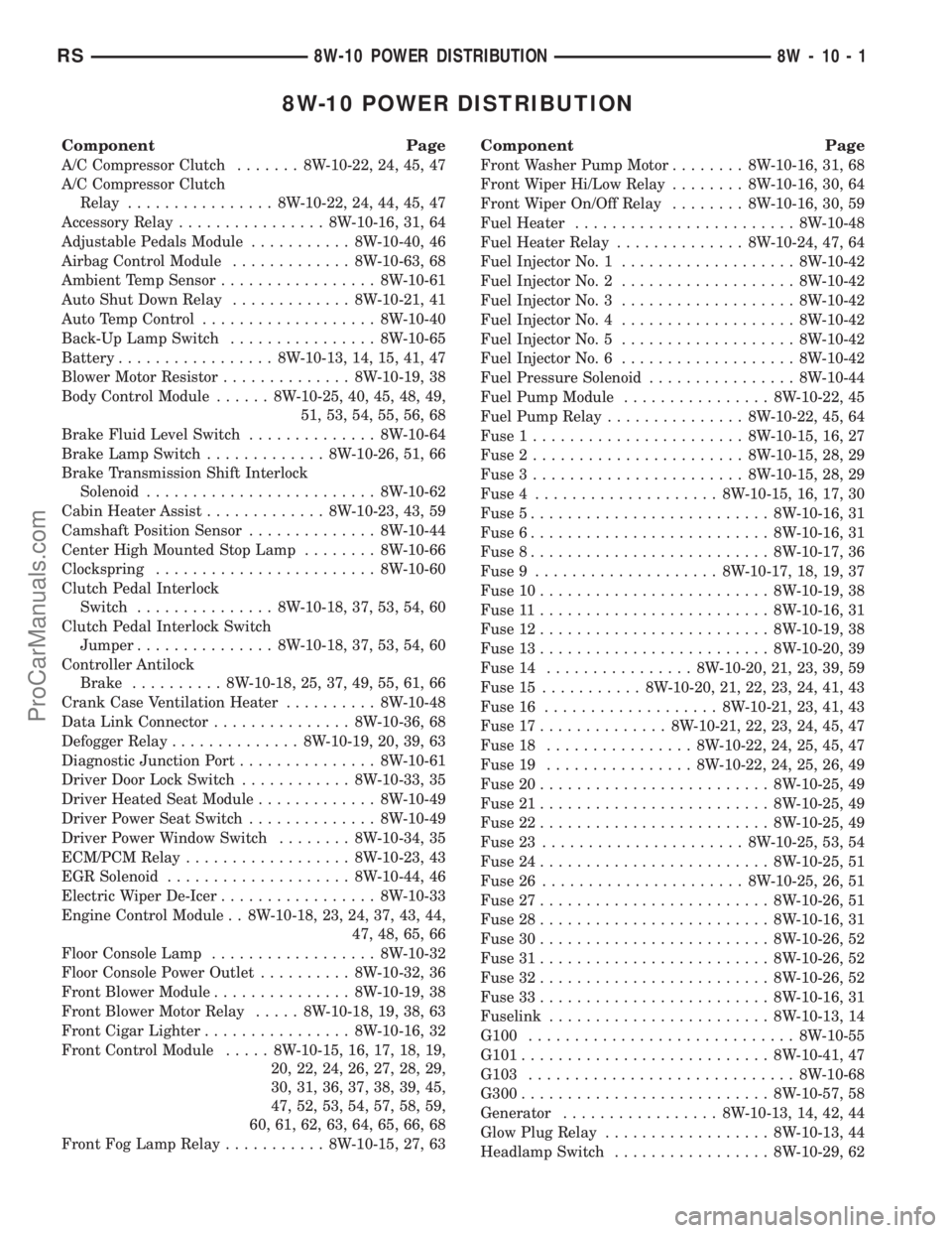
8W-10 POWER DISTRIBUTION
Component Page
A/C Compressor Clutch....... 8W-10-22, 24, 45, 47
A/C Compressor Clutch
Relay................ 8W-10-22, 24, 44, 45, 47
Accessory Relay................ 8W-10-16, 31, 64
Adjustable Pedals Module........... 8W-10-40, 46
Airbag Control Module............. 8W-10-63, 68
Ambient Temp Sensor................. 8W-10-61
Auto Shut Down Relay............. 8W-10-21, 41
Auto Temp Control................... 8W-10-40
Back-Up Lamp Switch................ 8W-10-65
Battery................. 8W-10-13, 14, 15, 41, 47
Blower Motor Resistor.............. 8W-10-19, 38
Body Control Module...... 8W-10-25, 40, 45, 48, 49,
51, 53, 54, 55, 56, 68
Brake Fluid Level Switch.............. 8W-10-64
Brake Lamp Switch............. 8W-10-26, 51, 66
Brake Transmission Shift Interlock
Solenoid......................... 8W-10-62
Cabin Heater Assist............. 8W-10-23, 43, 59
Camshaft Position Sensor.............. 8W-10-44
Center High Mounted Stop Lamp........ 8W-10-66
Clockspring........................ 8W-10-60
Clutch Pedal Interlock
Switch............... 8W-10-18, 37, 53, 54, 60
Clutch Pedal Interlock Switch
Jumper............... 8W-10-18, 37, 53, 54, 60
Controller Antilock
Brake.......... 8W-10-18, 25, 37, 49, 55, 61, 66
Crank Case Ventilation Heater.......... 8W-10-48
Data Link Connector............... 8W-10-36, 68
Defogger Relay.............. 8W-10-19, 20, 39, 63
Diagnostic Junction Port............... 8W-10-61
Driver Door Lock Switch............ 8W-10-33, 35
Driver Heated Seat Module............. 8W-10-49
Driver Power Seat Switch.............. 8W-10-49
Driver Power Window Switch........ 8W-10-34, 35
ECM/PCM Relay.................. 8W-10-23, 43
EGR Solenoid.................... 8W-10-44, 46
Electric Wiper De-Icer................. 8W-10-33
Engine Control Module . . 8W-10-18, 23, 24, 37, 43, 44,
47, 48, 65, 66
Floor Console Lamp.................. 8W-10-32
Floor Console Power Outlet.......... 8W-10-32, 36
Front Blower Module............... 8W-10-19, 38
Front Blower Motor Relay..... 8W-10-18, 19, 38, 63
Front Cigar Lighter................ 8W-10-16, 32
Front Control Module..... 8W-10-15, 16, 17, 18, 19,
20, 22, 24, 26, 27, 28, 29,
30, 31, 36, 37, 38, 39, 45,
47, 52, 53, 54, 57, 58, 59,
60, 61, 62, 63, 64, 65, 66, 68
Front Fog Lamp Relay........... 8W-10-15, 27, 63
Component Page
Front Washer Pump Motor........ 8W-10-16, 31, 68
Front Wiper Hi/Low Relay........ 8W-10-16, 30, 64
Front Wiper On/Off Relay........ 8W-10-16, 30, 59
Fuel Heater........................ 8W-10-48
Fuel Heater Relay.............. 8W-10-24, 47, 64
Fuel Injector No. 1................... 8W-10-42
Fuel Injector No. 2................... 8W-10-42
Fuel Injector No. 3................... 8W-10-42
Fuel Injector No. 4................... 8W-10-42
Fuel Injector No. 5................... 8W-10-42
Fuel Injector No. 6................... 8W-10-42
Fuel Pressure Solenoid................ 8W-10-44
Fuel Pump Module................ 8W-10-22, 45
Fuel Pump Relay............... 8W-10-22, 45, 64
Fuse 1....................... 8W-10-15, 16, 27
Fuse 2....................... 8W-10-15, 28, 29
Fuse 3....................... 8W-10-15, 28, 29
Fuse 4.................... 8W-10-15, 16, 17, 30
Fuse 5.......................... 8W-10-16, 31
Fuse 6.......................... 8W-10-16, 31
Fuse 8.......................... 8W-10-17, 36
Fuse 9.................... 8W-10-17, 18, 19, 37
Fuse 10......................... 8W-10-19, 38
Fuse 11......................... 8W-10-16, 31
Fuse 12......................... 8W-10-19, 38
Fuse 13......................... 8W-10-20, 39
Fuse 14................ 8W-10-20, 21, 23, 39, 59
Fuse 15........... 8W-10-20, 21, 22, 23, 24, 41, 43
Fuse 16................... 8W-10-21, 23, 41, 43
Fuse 17.............. 8W-10-21, 22, 23, 24, 45, 47
Fuse 18................ 8W-10-22, 24, 25, 45, 47
Fuse 19................ 8W-10-22, 24, 25, 26, 49
Fuse 20......................... 8W-10-25, 49
Fuse 21......................... 8W-10-25, 49
Fuse 22......................... 8W-10-25, 49
Fuse 23...................... 8W-10-25, 53, 54
Fuse 24......................... 8W-10-25, 51
Fuse 26...................... 8W-10-25, 26, 51
Fuse 27......................... 8W-10-26, 51
Fuse 28......................... 8W-10-16, 31
Fuse 30......................... 8W-10-26, 52
Fuse 31......................... 8W-10-26, 52
Fuse 32......................... 8W-10-26, 52
Fuse 33......................... 8W-10-16, 31
Fuselink........................ 8W-10-13, 14
G100............................. 8W-10-55
G101........................... 8W-10-41, 47
G103............................. 8W-10-68
G300........................... 8W-10-57, 58
Generator................. 8W-10-13, 14, 42, 44
Glow Plug Relay.................. 8W-10-13, 44
Headlamp Switch................. 8W-10-29, 62
RS8W-10 POWER DISTRIBUTION8W-10-1
ProCarManuals.com
Page 746 of 2399
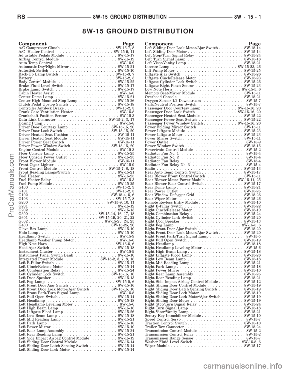
8W-15 GROUND DISTRIBUTION
Component PageA/C Compressor Clutch...................8W-15-7, 8
A/C- Heater Control....................8W-15-9, 11
Adjustable Pedals Module..................8W-15-17
Airbag Control Module....................8W-15-12
Auto Temp Control.......................8W-15-9
Automatic Day/Night Mirror.................8W-15-21
Autostick Switch........................8W-15-10
Back-Up Lamp Switch....................8W-15-3, 7
Battery.............................8W-15-2, 3
Body Control Module.....................8W-15-22
Brake Fluid Level Switch...................8W-15-17
Brake Lamp Switch......................8W-15-17
Cabin Heater Assist.......................8W-15-8
Center Dome Lamp......................8W-15-21
Center High Mounted Stop Lamp..............8W-15-26
Clutch Pedal Upstop Switch.................8W-15-18
Controller Antilock Brake..................8W-15-2, 3
Crank Case Ventilation Heater................8W-15-8
Crankshaft Position Sensor..................8W-15-3
Data Link Connector..................8W-15-2, 3, 17
Dosing Pump...........................8W-15-8
Driver Door Courtesy Lamp...............8W-15-15, 20
Driver Door Lock Switch.................8W-15-15, 20
Driver Heated Seat Cushion.................8W-15-11
Driver Heated Seat Module.................8W-15-11
Driver Power Seat Switch..................8W-15-11
Driver Power Window Switch..............8W-15-15, 20
Engine Control Module.....................8W-15-3
Floor Console Lamp......................8W-15-25
Floor Console Power Outlet.................8W-15-25
Front Blower Module.....................8W-15-11
Front Cigar Lighter.......................8W-15-9
Front Control Module..................8W-15-7, 8, 18
Front Reading Lamps/Switch................8W-15-21
Fuel Heater...........................8W-15-25
Fuel Heater Relay........................8W-15-3
Fuel Pump Module.......................8W-15-25
G100..............................8W-15-2, 3
G101..............................8W-15-2, 3
G102.............................8W-15-4, 5, 6
G103..............................8W-15-7, 8
G200...........................8W-15-9, 10, 11
G201...............................8W-15-12
G202...............................8W-15-13
G300........................8W-15-14, 16, 17, 18
G301........................8W-15-19, 20, 21, 22
G302...........................8W-15-23, 24, 25
G400.............................8W-15-25, 26
Glove Box Lamp........................8W-15-10
Halo Lamp............................8W-15-10
Headlamp Switch........................8W-15-9
Headlamp Washer Pump Motor................8W-15-6
High Note Horn........................8W-15-5, 6
Hood Ajar Switch........................8W-15-18
Instrument Cluster.......................8W-15-9
Instrument Panel Switch Bank...............8W-15-10
Integrated Power Module............8W-15-2, 3, 7, 8, 18
Left B-Pillar Switch......................8W-15-17
Left Cinch/Release Motor...................8W-15-14
Left Combination Relay....................8W-15-24
Left Cylinder Lock Switch................8W-15-15, 16
Left Door Speaker.......................8W-15-13
Left Fog Lamp........................8W-15-5, 6
Left Front Door Ajar Switch.................8W-15-16
Left Front Door Lock Motor/Ajar Switch.......8W-15-15, 16
Left Front Park/Turn Signal Lamp..............8W-15-5
Left Full Open Switch.....................8W-15-14
Left Headlamp.........................8W-15-18
Left Headlamp Leveling Motor................8W-15-6
Left High Beam Lamp....................8W-15-18
Left Liftgate Flood Lamp...................8W-15-26
Left Low Beam Lamp.....................8W-15-18
Left Mid Reading Lamp....................8W-15-21
Left Park Lamp.........................8W-15-18
Left Power Mirror.......................8W-15-10
Left Rear Lamp Assembly..................8W-15-24
Left Rear Reading Lamp...................8W-15-21
Left Side Impact Airbag Control Module.........8W-15-12
Left Sliding Door Control Module..............8W-15-14
Left Sliding Door Latch Sensing Switch..........8W-15-14
Left Sliding Door Lock Motor................8W-15-14Component PageLeft Sliding Door Lock Motor/Ajar Switch.........8W-15-14
Left Sliding Door Motor....................8W-15-14
Left Stop/Turn Signal Relay.................8W-15-24
Left Turn Signal Lamp....................8W-15-18
Left Visor/Vanity Lamp....................8W-15-21
License Lamp........................8W-15-23, 26
Lift Pump Motor........................8W-15-25
Liftgate Ajar Switch......................8W-15-26
Liftgate Cinch/Release Motor................8W-15-23
Liftgate Cylinder Lock Switch................8W-15-26
Liftgate Right Pinch Sensor.................8W-15-23
Low Note Horn........................8W-15-5, 6
Memory Seat/Mirror Module.................8W-15-11
Overhead Console.......................8W-15-21
Oxygen Sensor 1/2 Downstream...............8W-15-7
Park/Neutral Position Switch.................8W-15-7
Passenger Door Courtesy Lamp............8W-15-16, 20
Passenger Door Lock Switch..............8W-15-16, 20
Passenger Heated Seat Module...............8W-15-22
Passenger Power Seat Switch................8W-15-22
Passenger Power Window Switch............8W-15-16, 20
Power Folding Mirror Switch................8W-15-11
Power Liftgate Module....................8W-15-23
Power Liftgate Motor.....................8W-15-23
Power Mirror Switch......................8W-15-11
Power Outlet...........................8W-15-9
Power Window Switch.....................8W-15-15
Powertrain Control Module..................8W-15-2
Radiator Fan No. 1.......................8W-15-4
Radiator Fan No. 2.......................8W-15-4
Radiator Fan Relay.......................8W-15-4
Radiator Fan Relay No. 3...................8W-15-4
Radio...............................8W-15-13
Rear Auto Temp Control Switch...............8W-15-17
Rear Blower Front Control Switch.............8W-15-11
Rear Blower Motor Power Module...........8W-15-11, 25
Rear Blower Rear Control Switch..............8W-15-17
Rear Dome Lamp........................8W-15-21
Rear Power Outlet.......................8W-15-25
Rear Window Defogger Grid.................8W-15-26
Rear Wiper Motor.......................8W-15-26
Remote Keyless Entry Module................8W-15-10
Right B-Pillar Switch.....................8W-15-22
Right Cinch/Release Motor..................8W-15-19
Right Combination Relay...................8W-15-24
Right Cylinder Lock Switch.................8W-15-20
Right Door Speaker......................8W-15-13
Right Fog Lamp........................8W-15-5, 6
Right Front Door Ajar Switch................8W-15-20
Right Front Door Lock Motor/Ajar Switch.........8W-15-20
Right Front Park/Turn Signal Lamp.............8W-15-5
Right Full Open Switch....................8W-15-19
Right Headlamp........................8W-15-18
Right Headlamp Leveling Motor...............8W-15-6
Right High Beam Lamp....................8W-15-18
Right Liftgate Flood Lamp..................8W-15-26
Right Low Beam Lamp....................8W-15-18
Right Mid Reading Lamp...................8W-15-21
Right Park Lamp........................8W-15-18
Right Power Mirror......................8W-15-10
Right Rear Lamp Assembly.................8W-15-25
Right Rear Reading Lamp..................8W-15-21
Right Side Impact Airbag Control Module.........8W-15-12
Right Sliding Door Control Module.............8W-15-19
Right Sliding Door Latch Sensing Switch.........8W-15-19
Right Sliding Door Lock Motor...............8W-15-19
Right Sliding Door Lock Motor/Ajar Switch........8W-15-19
Right Sliding Door Motor...................8W-15-19
Right Stop/Turn Signal Relay................8W-15-24
Right Turn Signal Lamp...................8W-15-18
Right Visor/Vanity Lamp...................8W-15-21
Sentry Key Immobilizer Module...............8W-15-10
Speed Control Servo.......................8W-15-7
Traction Control Switch....................8W-15-10
Trailer Tow Connector.....................8W-15-24
Transmission Control Module.................8W-15-2
Transmission Control Relay..................8W-15-2
Transmission Range Sensor..................8W-15-7
Washer Fluid Level Switch.................8W-15-5, 6
Wiper Module..........................8W-15-17
RS8W-15 GROUND DISTRIBUTION8W-15-1
ProCarManuals.com
Page 1033 of 2399

Component Page
C322 (Memory)..................... 8W-80-39
C322 (Memory)..................... 8W-80-39
C324 (Manual Sliding Door)........... 8W-80-39
C324 (Manual Sliding Door)........... 8W-80-40
C325 (Manual Sliding Door)........... 8W-80-40
C325 (Manual Sliding Door)........... 8W-80-40
C326............................. 8W-80-40
C326............................. 8W-80-40
C327............................. 8W-80-40
C327............................. 8W-80-41
C329 (Diesel)....................... 8W-80-41
C329 (Diesel)....................... 8W-80-41
C330 (Diesel)....................... 8W-80-41
C330 (Diesel)....................... 8W-80-41
C331 (Diesel)....................... 8W-80-42
C331 (Diesel)....................... 8W-80-42
C332 (ATC)........................ 8W-80-42
C332 (ATC)........................ 8W-80-42
Cabin Heater Assist C1 (Diesel)........ 8W-80-42
Cabin Heater Assist C2 (Diesel)........ 8W-80-43
Camshaft Position Sensor (Diesel)...... 8W-80-43
Camshaft Position Sensor (Gas)........ 8W-80-43
CD Changer....................... 8W-80-43
Center Dome Lamp (Base/High Line).... 8W-80-43
Center High Mounted Stop Lamp....... 8W-80-44
Clockspring C1..................... 8W-80-44
Clockspring C2..................... 8W-80-44
Clockspring C3..................... 8W-80-44
Clockspring C4..................... 8W-80-44
Clockspring C5..................... 8W-80-45
Clutch Pedal Interlock Switch (MTX).... 8W-80-45
Clutch Pedal Interlock Switch Jumper
(ATX) .......................... 8W-80-45
Clutch Pedal Upstop Switch (Diesel)..... 8W-80-45
Controller Antilock Brake............. 8W-80-46
Crank Case Ventilation Heater (Diesel) . . 8W-80-46
Crankshaft Position Sensor (Diesel)..... 8W-80-46
Crankshaft Position Sensor (Gas)....... 8W-80-47
Data Link Connector................. 8W-80-47
Diagnostic Junction Port.............. 8W-80-47
Dosing Pump (Diesel)................ 8W-80-48
Driver Airbag C1.................... 8W-80-48
Driver Airbag C2.................... 8W-80-48
Driver Blend Door Actuator (ATC)...... 8W-80-48
Driver Blend Door Actuator (MTC)...... 8W-80-48
Driver Door Courtesy Lamp........... 8W-80-49
Driver Door Lock Switch.............. 8W-80-49
Driver Heated Seat Back............. 8W-80-49
Driver Heated Seat Cushion........... 8W-80-49
Driver Heated Seat Module C1......... 8W-80-49
Driver Heated Seat Module C2......... 8W-80-50
Driver Heated Seat Module C3......... 8W-80-50
Driver Power Seat Front Riser Motor.... 8W-80-50Component Page
Driver Power Seat Front Riser
Position Sensor................... 8W-80-50
Driver Power Seat Horizontal Motor..... 8W-80-50
Driver Power Seat Horizontal
Position Sensor................... 8W-80-51
Driver Power Seat Rear Riser Motor.... 8W-80-51
Driver Power Seat Rear Riser
Position Sensor................... 8W-80-51
Driver Power Seat Recliner Motor...... 8W-80-51
Driver Power Seat Recliner
Position Sensor................... 8W-80-51
Driver Power Seat Switch............. 8W-80-52
Driver Power Window Motor........... 8W-80-52
Driver Power Window Switch
(Except Lowline).................. 8W-80-52
Driver Power Window Switch (Lowline) . . 8W-80-53
Driver Power Window Switch (RHD).... 8W-80-53
Driver Seat Belt Switch.............. 8W-80-53
Driver Seat Belt Tensioner............ 8W-80-53
EGR Solenoid (Diesel)................ 8W-80-54
EGR Solenoid (Gas)................. 8W-80-54
Electric Wiper De-Icer C1............. 8W-80-54
Electric Wiper De-Icer C2............. 8W-80-54
Engine Control Module C1 (Diesel)...... 8W-80-55
Engine Control Module C2 (Diesel)...... 8W-80-57
Engine Coolant Temp Sensor (Diesel).... 8W-80-57
Engine Coolant Temp Sensor (Gas)...... 8W-80-58
Engine Oil Pressure Sensor (Diesel)..... 8W-80-58
Engine Oil Pressure Switch (Gas)....... 8W-80-58
Engine Oil Temperature Sensor (Diesel) . . 8W-80-58
EVAP/Purge Solenoid (Gas)............ 8W-80-58
Evaporator Temperature Sensor........ 8W-80-59
Floor Console Lamp................. 8W-80-59
Floor Console Power Outlet........... 8W-80-59
Front Blower Module C1 (ATC)......... 8W-80-59
Front Blower Module C2 (ATC)......... 8W-80-59
Front Cigar Lighter................. 8W-80-60
Front Reading Lamps/Switch.......... 8W-80-60
Front Washer Pump Motor............ 8W-80-60
Fuel Heater (Diesel)................. 8W-80-60
Fuel Injector No. 1 (2.4L/3.3L/3.8L)..... 8W-80-60
Fuel Injector No. 1 (Diesel)............ 8W-80-61
Fuel Injector No. 2 (2.4L/3.3L/3.8L)..... 8W-80-61
Fuel Injector No. 2 (Diesel)............ 8W-80-61
Fuel Injector No. 3 (2.4L/3.3L/3.8L)..... 8W-80-61
Fuel Injector No. 3 (Diesel)............ 8W-80-61
Fuel Injector No. 4 (2.4L/3.3L/3.8L)..... 8W-80-62
Fuel Injector No. 4 (Diesel)............ 8W-80-62
Fuel Injector No. 5 (3.3L/3.8L)......... 8W-80-62
Fuel Injector No. 6 (3.3L/3.8L)......... 8W-80-62
Fuel Pressure Sensor (Diesel).......... 8W-80-62
Fuel Pressure Solenoid (Diesel)......... 8W-80-63
Fuel Pump Module.................. 8W-80-63
Generator......................... 8W-80-63
8W - 80 - 2 8W-80 CONNECTOR PIN-OUTSRS
ProCarManuals.com
Page 1150 of 2399

CONNECTOR NAME/NUMBER COLOR LOCATION FIG.
C325 BK Right Sliding Door 27
C326 YL At Driver Side Airbag N/S
C327 YL At Passenger Side Airbag N/S
C329 (Diesel) BK Left Rear Engine Compartment N/S
C330 (Diesel) LTGY Left Rear Engine Compartment N/S
C331 (Diesel) BK Left Rear Engine Compartment N/S
Cabin Heater Assist C1 (Diesel) BK Top of Engine 11, 12
Cabin Heater Assist C2 (Diesel) BK Top of Engine 11, 12
Camshaft Position Sensor (Gas) BK Rear of Cylinder Head
Right Side of EngineN/S
Camshaft Position Sensor (Diesel) BK Rear of Cylinder Head 11, 12
CD Changer Behind CD Changer N/S
Center Dome Lamp GY At Lamp N/S
Center High Mounted Stop Lamp BK At Lamp 42
Clockspring - C1 WT Steering Column 15, 16, 17, 18, 26
Clockspring - C2 YL Steering Column 15, 16, 17, 18, 26
Clockspring - C3 BK Steering Column N/S
Clockspring - C4 BK Steering Column N/S
Clockspring - C5 YL Steering Column N/S
Clutch Pedal Interlock Switch
(Diesel)RD At Switch/Driver Side 36
Clutch Pedal Upstop Switch
(Diesel)BK At Switch/Driver Side 36
Controller Anti-Lock Brake BK Right Side of Engine Compartment 9, 10, 12, 13, 14
Crank Case Ventilation Heater
(Diesel)BK Top of Cylinder Head 11
Crankshaft Position Sensor (Diesel) BK Rear of Engine 12
Crankshaft Position Sensor (Gas) BK Rear of Engine 9, 13
Data Link Connector WT Lower Instrument Panel Near Steering
Column35, 36
Diagnostic Junction Port BK Lower Instrument Panel Near Steering
Column35, 36
Dosing Pump BK Top of Engine N/S
Driver Airbag C1 BN Steering Column N/S
Driver Airbag C2 BK Steering Column N/S
Driver Blend Actuator (ATC) GY On HVAC N/S
Driver Blend Actuator (MTC) GY On HVAC N/S
Driver Door Courtesy Lamp GY At Lamp N/S
Driver Door Lock Switch BK At Switch N/S
Driver Heated Seat Back GN At Seat N/S
Driver Heated Seat Cushion BK At Seat N/S
Driver Heated Seat Module C1 GY Driver Heated Seat N/S
Driver Heated Seat Module C2 GY Driver Heated Seat Back N/S
Driver Heated Seat Module C3 GN At Seat N/S
RS8W-91 CONNECTOR/GROUND/SPLICE LOCATION8W-91-3
CONNECTOR/GROUND/SPLICE LOCATION (Continued)
ProCarManuals.com
Page 1151 of 2399

CONNECTOR NAME/NUMBER COLOR LOCATION FIG.
Driver Power Seat Front Riser
MotorRD At Seat N/S
Driver Power Seat Horizontal Motor BK At Seat N/S
Driver Power Seat Rear Riser
MotorRD At Seat N/S
Driver Power Seat Recliner Motor GN At Seat N/S
Driver Power Seat Switch GN At Switch N/S
Driver Power Window Motor RD At Motor N/S
Driver Power Window Switch GN At Switch N/S
Driver Power Window Switch
(RHD)NAT At Switch N/S
Driver Seatbelt Switch WT At Switch on Seat Harness N/S
Driver Seatbelt Tensioner On Seat Harness N/S
EGR Solenoid (Diesel) BK Above Transmission
Right Side of EngineN/S
EGR Solenoid GY Above Transmission
Right Side of Engine9, 10, 11, 13
Electric Wiper De-Icer-C1 WT Right Side Instrument Panel 15, 1923
Electric Wiper De-Icer-C2 WT Left Side Instrument Panel 15, 16, 22
Engine Control Module C1 (Diesel) BK Right Side of Engine 11
Engine Control Module C2 (Diesel) BK Right Side of Engine 11
Engine Coolant Temperature
Sensor (Gas)BK On Cylinder Block N/S
Engine Coolant Temperature
Sensor (Diesel)BL On Cylinder Block 11
Engine Oil Pressure Sensor
(Diesel)BK Rear of Engine 12
Engine Oil Pressure Switch (Gas) LTGN On Cylinder Block 9
Engine Oil Temperature Sensor
(Diesel)BK Rear of Engine 12
EVAP/Purge Solenoid BK Right Motor Mount 9, 13
Evaporator Temperature Sensor BK Right Side of HVAC N/S
Floor Console Lamp BK At Lamp N/S
Floor Console Power Outlet RD At Front Console N/S
Front Blower Module C1 (ATC) BK On HVAC N/S
Front Blower Module C2 (ATC) BK On HVAC N/S
Front Cigar Lighter RD/NAT Rear of Lighter 15, 18, 20
Front Reading Lamps/Switch BK At Switch N/S
Front Washer Pump Motor BK Right Fender Well 3
Fuel Heater (Diesel) BK Left Rear Engine Compartment N/S
Fuel Injector No.1 BK At Fuel Injector N/S
Fuel Injector No.1 (Diesel) BK At Fuel Injector 11
Fuel Injector No.2 BK At Fuel Injector N/S
Fuel Injector No.2 (Diesel) BK At Fuel Injector 11
8W - 91 - 4 8W-91 CONNECTOR/GROUND/SPLICE LOCATIONRS
CONNECTOR/GROUND/SPLICE LOCATION (Continued)
ProCarManuals.com
Page 1198 of 2399

(4) The coil ground terminal (85) is connected to
the electromagnet in the relay. It receives battery
feed to energize the accessory relay when the ignition
switch is in the Accessory or On positions. Turn the
ignition switch to the On position. Check for battery
voltage at the fused ignition switch output (acc/run)
circuit cavity for relay terminal 85 in the IPM recep-
tacle for the accessory relay. If OK, go to Step 5. If
not OK, repair the open fused ignition switch output
(acc/run) circuit to the ignition switch as required.
(5) The coil battery terminal (86) is connected to
the electromagnet in the relay. The IPM cavity for
this terminal should have continuity to ground at all
times. If not OK, repair the open ground circuit to
ground as required.
REMOVAL
(1) Disconnect and isolate the battery negative
cable.
(2) Remove the Integrated Power Module (IPM)
cover from the IPM.
(3) Remove the accessory relay from the IPM.
Refer to the IPM cover for relay location.
INSTALLATION
(1) Position the accessory relay in the proper
receptacle in the Integrated Power Module (IPM).
(2) Push in firmly on the accessory relay until the
terminals are fully seated in the terminal cavities in
the IPM receptacle.
(3) Install the IPM cover.
(4) Reconnect the battery negative cable.
INTEGRATED POWER MODULE
DESCRIPTION
The Integrated Power Module (IPM) is a combina-
tion of the Power Distribution Center (PDC) and the
Front Control Module (FCM). The IPM is located in
the engine compartment, next to the battery on this
model (Fig. 2). The power distribution center mates
directly with the Front Control Module (FCM) to
form the IPM Fuse and Relay Center. The power dis-
tribution center (PDC) is a printed circuit board
based module that contains fuses and relays, while
the front control module contains the electronics con-
trolling the IPM and other functions. This IPM con-
nects directly to the battery positive via a four pin
connector. The ground connection is via two other
connectors. The IPM provides the primary means of
voltage distribution and protection for the entire
vehicle.
The molded plastic IPM housing includes a base
and cover. The IPM cover is easily opened or removed
for service access by squeezing the two marked coverlatches and has a fuse and relay layout map integral
to the inside surface of the cover. This IPM housing
base and cover are secured in place by an IPM
mounting bracket. This mounting bracket is designed
to allow the IPM to rotate counter-clockwise once the
locking tab is disengaged. The IPM mounting bracket
is secured in place by bolts threaded into the left
front wheel house.
Replaceable components of the IPM assembly are
broken down into the following components: the
Power Distribution Center (PDC) (without fuses or
relays), the IPM cover, the Front Control Module
(FCM), the IPM mounting bracket, IPM bracket
retaining clips and the IPM assembly which includes
the power distribution center, the cover and FCM.
Refer to the Front Control Module in the Elec-
tronic Control Module sectionof this service
manual for information on the FCM.
OPERATION
All of the current from the battery and the gener-
ator output enters the Integrated Power Module
(IPM) via a four- pin connector on the bottom of the
module. The IPM cover is unlatched and opened or
removed to access the fuses or relays. Internal con-
nections of all of the power distribution center cir-
cuits is accomplished by a combination of bus bars
and a printed circuit board. Refer to the Wiring sec-
Fig. 2 BATTERY THERMAL GUARD
1 - BATTERY THERMAL GUARD
2 - INTEGRATED POWER MODULE
3 - FRONT CONTROL MODULE
RS8W-97 POWER DISTRIBUTION SYSTEM8W-97-3
ACCESSORY RELAY (Continued)
ProCarManuals.com
Page 1203 of 2399
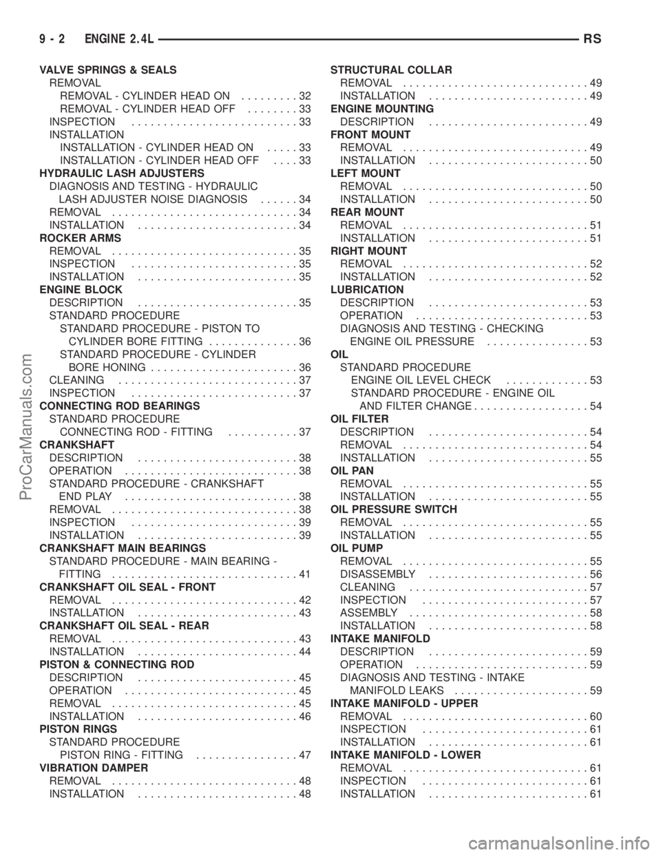
VALVE SPRINGS & SEALS
REMOVAL
REMOVAL - CYLINDER HEAD ON.........32
REMOVAL - CYLINDER HEAD OFF........33
INSPECTION..........................33
INSTALLATION
INSTALLATION - CYLINDER HEAD ON.....33
INSTALLATION - CYLINDER HEAD OFF....33
HYDRAULIC LASH ADJUSTERS
DIAGNOSIS AND TESTING - HYDRAULIC
LASH ADJUSTER NOISE DIAGNOSIS......34
REMOVAL.............................34
INSTALLATION.........................34
ROCKER ARMS
REMOVAL.............................35
INSPECTION..........................35
INSTALLATION.........................35
ENGINE BLOCK
DESCRIPTION.........................35
STANDARD PROCEDURE
STANDARD PROCEDURE - PISTON TO
CYLINDER BORE FITTING..............36
STANDARD PROCEDURE - CYLINDER
BORE HONING.......................36
CLEANING............................37
INSPECTION..........................37
CONNECTING ROD BEARINGS
STANDARD PROCEDURE
CONNECTING ROD - FITTING...........37
CRANKSHAFT
DESCRIPTION.........................38
OPERATION...........................38
STANDARD PROCEDURE - CRANKSHAFT
ENDPLAY ...........................38
REMOVAL.............................38
INSPECTION..........................39
INSTALLATION.........................39
CRANKSHAFT MAIN BEARINGS
STANDARD PROCEDURE - MAIN BEARING -
FITTING.............................41
CRANKSHAFT OIL SEAL - FRONT
REMOVAL.............................42
INSTALLATION.........................43
CRANKSHAFT OIL SEAL - REAR
REMOVAL.............................43
INSTALLATION.........................44
PISTON & CONNECTING ROD
DESCRIPTION.........................45
OPERATION...........................45
REMOVAL.............................45
INSTALLATION.........................46
PISTON RINGS
STANDARD PROCEDURE
PISTON RING - FITTING................47
VIBRATION DAMPER
REMOVAL.............................48
INSTALLATION.........................48STRUCTURAL COLLAR
REMOVAL.............................49
INSTALLATION.........................49
ENGINE MOUNTING
DESCRIPTION.........................49
FRONT MOUNT
REMOVAL.............................49
INSTALLATION.........................50
LEFT MOUNT
REMOVAL.............................50
INSTALLATION.........................50
REAR MOUNT
REMOVAL.............................51
INSTALLATION.........................51
RIGHT MOUNT
REMOVAL.............................52
INSTALLATION.........................52
LUBRICATION
DESCRIPTION.........................53
OPERATION...........................53
DIAGNOSIS AND TESTING - CHECKING
ENGINE OIL PRESSURE................53
OIL
STANDARD PROCEDURE
ENGINE OIL LEVEL CHECK.............53
STANDARD PROCEDURE - ENGINE OIL
AND FILTER CHANGE..................54
OIL FILTER
DESCRIPTION.........................54
REMOVAL.............................54
INSTALLATION.........................55
OIL PAN
REMOVAL.............................55
INSTALLATION.........................55
OIL PRESSURE SWITCH
REMOVAL.............................55
INSTALLATION.........................55
OIL PUMP
REMOVAL.............................55
DISASSEMBLY.........................56
CLEANING............................57
INSPECTION..........................57
ASSEMBLY............................58
INSTALLATION.........................58
INTAKE MANIFOLD
DESCRIPTION.........................59
OPERATION...........................59
DIAGNOSIS AND TESTING - INTAKE
MANIFOLD LEAKS.....................59
INTAKE MANIFOLD - UPPER
REMOVAL.............................60
INSPECTION..........................61
INSTALLATION.........................61
INTAKE MANIFOLD - LOWER
REMOVAL.............................61
INSPECTION..........................61
INSTALLATION.........................61
9 - 2 ENGINE 2.4LRS
ProCarManuals.com
Page 1209 of 2399
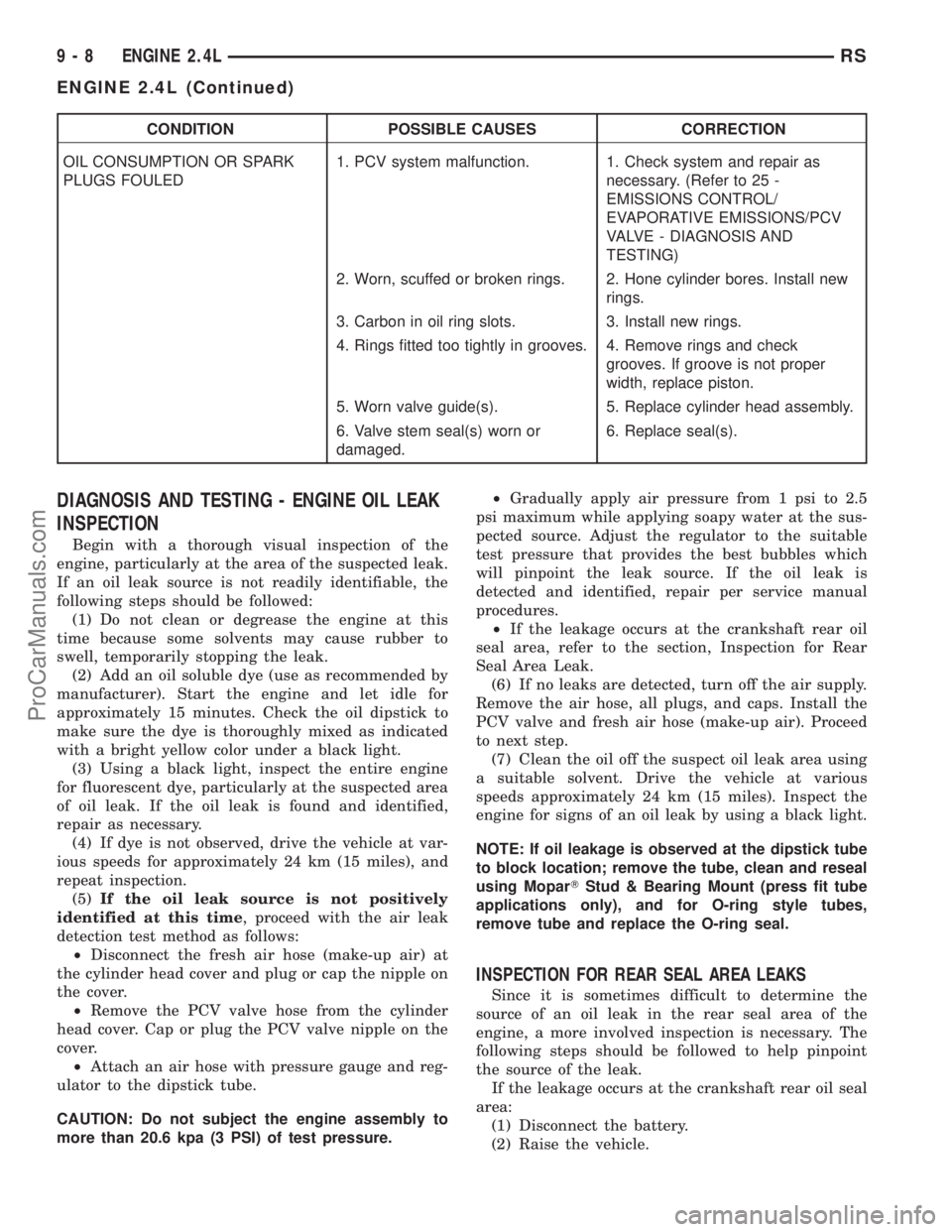
CONDITION POSSIBLE CAUSES CORRECTION
OIL CONSUMPTION OR SPARK
PLUGS FOULED1. PCV system malfunction. 1. Check system and repair as
necessary. (Refer to 25 -
EMISSIONS CONTROL/
EVAPORATIVE EMISSIONS/PCV
VALVE - DIAGNOSIS AND
TESTING)
2. Worn, scuffed or broken rings. 2. Hone cylinder bores. Install new
rings.
3. Carbon in oil ring slots. 3. Install new rings.
4. Rings fitted too tightly in grooves. 4. Remove rings and check
grooves. If groove is not proper
width, replace piston.
5. Worn valve guide(s). 5. Replace cylinder head assembly.
6. Valve stem seal(s) worn or
damaged.6. Replace seal(s).
DIAGNOSIS AND TESTING - ENGINE OIL LEAK
INSPECTION
Begin with a thorough visual inspection of the
engine, particularly at the area of the suspected leak.
If an oil leak source is not readily identifiable, the
following steps should be followed:
(1) Do not clean or degrease the engine at this
time because some solvents may cause rubber to
swell, temporarily stopping the leak.
(2) Add an oil soluble dye (use as recommended by
manufacturer). Start the engine and let idle for
approximately 15 minutes. Check the oil dipstick to
make sure the dye is thoroughly mixed as indicated
with a bright yellow color under a black light.
(3) Using a black light, inspect the entire engine
for fluorescent dye, particularly at the suspected area
of oil leak. If the oil leak is found and identified,
repair as necessary.
(4) If dye is not observed, drive the vehicle at var-
ious speeds for approximately 24 km (15 miles), and
repeat inspection.
(5)If the oil leak source is not positively
identified at this time, proceed with the air leak
detection test method as follows:
²Disconnect the fresh air hose (make-up air) at
the cylinder head cover and plug or cap the nipple on
the cover.
²Remove the PCV valve hose from the cylinder
head cover. Cap or plug the PCV valve nipple on the
cover.
²Attach an air hose with pressure gauge and reg-
ulator to the dipstick tube.
CAUTION: Do not subject the engine assembly to
more than 20.6 kpa (3 PSI) of test pressure.²Gradually apply air pressure from 1 psi to 2.5
psi maximum while applying soapy water at the sus-
pected source. Adjust the regulator to the suitable
test pressure that provides the best bubbles which
will pinpoint the leak source. If the oil leak is
detected and identified, repair per service manual
procedures.
²If the leakage occurs at the crankshaft rear oil
seal area, refer to the section, Inspection for Rear
Seal Area Leak.
(6) If no leaks are detected, turn off the air supply.
Remove the air hose, all plugs, and caps. Install the
PCV valve and fresh air hose (make-up air). Proceed
to next step.
(7) Clean the oil off the suspect oil leak area using
a suitable solvent. Drive the vehicle at various
speeds approximately 24 km (15 miles). Inspect the
engine for signs of an oil leak by using a black light.
NOTE: If oil leakage is observed at the dipstick tube
to block location; remove the tube, clean and reseal
using MoparTStud & Bearing Mount (press fit tube
applications only), and for O-ring style tubes,
remove tube and replace the O-ring seal.
INSPECTION FOR REAR SEAL AREA LEAKS
Since it is sometimes difficult to determine the
source of an oil leak in the rear seal area of the
engine, a more involved inspection is necessary. The
following steps should be followed to help pinpoint
the source of the leak.
If the leakage occurs at the crankshaft rear oil seal
area:
(1) Disconnect the battery.
(2) Raise the vehicle.
9 - 8 ENGINE 2.4LRS
ENGINE 2.4L (Continued)
ProCarManuals.com