engine mount CHRYSLER CARAVAN 2002 Service Manual
[x] Cancel search | Manufacturer: CHRYSLER, Model Year: 2002, Model line: CARAVAN, Model: CHRYSLER CARAVAN 2002Pages: 2399, PDF Size: 57.96 MB
Page 1211 of 2399

Calibrate the tester according to the manufactur-
er's instructions. The shop air source for testing
should maintain 483 kPa (70 psi) minimum, 1,379
kPa (200 psi) maximum, with 552 kPa (80 psi) rec-
ommended.
Perform the test procedures on each cylinder
according to the tester manufacturer's instructions.
While testing, listen for pressurized air escaping
through the throttle body, tailpipe and oil filler cap
opening. Check for bubbles in the coolant.
All gauge pressure indications should be equal,
with no more than 25% leakage per cylinder.
FOR EXAMPLE:At 552 kPa (80 psi) input pres-
sure, a minimum of 414 kPa (60 psi) should be main-
tained in the cylinder.
STANDARD PROCEDURE
STANDARD PROCEDURE - ENGINE CORE AND
OIL GALLERY PLUGS
Using a blunt tool such as a drift and a hammer,
strike the bottom edge of the cup plug. With the cup
plug rotated, grasp firmly with pliers or other suit-
able tool and remove plug (Fig. 2).
CAUTION: Do not drive cup plug into the casting as
restricted cooling can result and cause serious
engine problems.Thoroughly clean inside of cup plug hole in cylin-
der block or head. Be sure to remove old sealer.
Lightly coat inside of cup plug hole with Mopart
Stud and Bearing Mount. Make certain the new plug
is cleaned of all oil or grease. Using proper drive
plug, drive plug into hole so that the sharp edge of
the plug is at least 0.5 mm (0.020 in.) inside the
lead-in chamfer.
It is not necessary to wait for curing of the sealant.
The cooling system can be refilled and the vehicle
placed in service immediately.
STANDARD PROCEDURE - REPAIR OF
DAMAGED OR WORN THREADS
Damaged or worn threads (excluding spark plug
and camshaft bearing cap attaching threads) can be
repaired. Essentially, this repair consists of drilling
out worn or damaged threads, tapping the hole with
a special Heli-Coil Tap, (or equivalent) and installing
an insert into the tapped hole. This brings the hole
back to its original thread size.
CAUTION: Be sure that the tapped holes maintain
the original center line.
Heli-Coil tools and inserts are readily available
from automotive parts jobbers.
STANDARD PROCEDURE - HYDROSTATIC
LOCKED ENGINE
When an engine is suspected to be hydrostatically
locked, regardless of what caused the problem, the
following steps should be used.
CAUTION: DO NOT use starter motor to rotate the
engine, severe damage may occur.
(1) Inspect air cleaner, induction system and
intake manifold to insure system is dry and clear of
foreign material.
(2) Remove negative battery cable.
(3) Place a shop towel around the spark plugs
when removing them from the engine. This will catch
any fluid that may possibly be in the cylinder under
pressure.
(4) With all spark plugs removed, rotate engine
crankshaft using a breaker bar and socket.
(5) Identify the fluid in the cylinder(s) (i.e., cool-
ant, fuel, oil or other).
(6) Make sure all fluid has been removed from the
cylinders. Inspect engine for damage (i.e., connecting
rods, pistons, valves, etc.)
(7) Repair engine or components as necessary to
prevent this problem from re-occurring.
Fig. 2 Core Hole Plug Removal
1 - CYLINDER BLOCK
2 - REMOVE PLUG WITH PLIERS
3 - STRIKE HERE WITH HAMMER
4 - DRIFT PUNCH
5 - CUP PLUG
9 - 10 ENGINE 2.4LRS
ENGINE 2.4L (Continued)
ProCarManuals.com
Page 1212 of 2399
CAUTION: Squirt approximately one teaspoon of oil
into the cylinders, rotate engine to lubricate the cyl-
inder walls to prevent damage on restart.
(8) Install new spark plugs.
(9) Drain engine oil and remove oil filter.
(10) Install a new oil filter.
(11) Fill engine with specified amount of approved
oil.
(12) Connect negative battery cable.
(13) Start engine and check for any leaks.
STANDARD PROCEDURE - FORM-IN-PLACE
GASKETS AND SEALERS
There are numerous places where form-in-place
gaskets are used on the engine. Care must be taken
when applying form-in-place gaskets to assure
obtaining the desired results.Do not use form-in-
place gasket material unless specified.Bead size,
continuity, and location are of great importance. Too
thin a bead can result in leakage while too much can
result in spill-over which can break off and obstruct
fluid feed lines. A continuous bead of the proper
width is essential to obtain a leak-free gasket.
There are numerous types of form-in-place gasket
materials that are used in the engine area. Mopart
Engine RTV GEN II, MopartATF-RTV, and Mopart
Gasket Maker gasket materials, each have different
properties and can not be used in place of the other.
MOPARtENGINE RTV GEN IIis used to seal
components exposed to engine oil. This material is a
specially designed black silicone rubber RTV that
retains adhesion and sealing properties when
exposed to engine oil. Moisture in the air causes the
material to cure. This material is available in three
ounce tubes and has a shelf life of one year. After one
year this material will not properly cure. Always
inspect the package for the expiration date before
use.
MOPARtATF RTVis a specifically designed
black silicone rubber RTV that retains adhesion and
sealing properties to seal components exposed to
automatic transmission fluid, engine coolants, and
moisture. This material is available in three ounce
tubes and has a shelf life of one year. After one year
this material will not properly cure. Always inspect
the package for the expiration date before use.
MOPARtGASKET MAKERis an anaerobic type
gasket material. The material cures in the absence of
air when squeezed between two metallic surfaces. It
will not cure if left in the uncovered tube. The
anaerobic material is for use between two machined
surfaces. Do not use on flexible metal flanges.
MOPARtBED PLATE SEALANTis a unique
(green-in-color) anaerobic type gasket material that
is specially made to seal the area between the bed-plate and cylinder block without disturbing the bear-
ing clearance or alignment of these components. The
material cures slowly in the absence of air when
torqued between two metallic surfaces, and will rap-
idly cure when heat is applied.
MOPARtGASKET SEALANTis a slow drying,
permanently soft sealer. This material is recom-
mended for sealing threaded fittings and gaskets
against leakage of oil and coolant. Can be used on
threaded and machined parts under all tempera-
tures. This material is used on engines with multi-
layer steel (MLS) cylinder head gaskets. This
material also will prevent corrosion. MopartGasket
Sealant is available in a 13 oz. aerosol can or 4oz./16
oz. can w/applicator.
SEALER APPLICATION
MopartGasket Maker material should be applied
sparingly 1 mm (0.040 in.) diameter or less of sealant
to one gasket surface. Be certain the material sur-
rounds each mounting hole. Excess material can eas-
ily be wiped off. Components should be torqued in
place within 15 minutes. The use of a locating dowel
is recommended during assembly to prevent smear-
ing material off the location.
MopartEngine RTV GEN II or ATF RTV gasket
material should be applied in a continuous bead
approximately 3 mm (0.120 in.) in diameter. All
mounting holes must be circled. For corner sealing, a
3.17 or 6.35 mm (1/8 or 1/4 in.) drop is placed in the
center of the gasket contact area. Uncured sealant
may be removed with a shop towel. Components
should be torqued in place while the sealant is still
wet to the touch (within 10 minutes). The usage of a
locating dowel is recommended during assembly to
prevent smearing material off the location.
MopartGasket Sealant in an aerosol can should be
applied using a thin, even coat sprayed completely
over both surfaces to be joined, and both sides of a
gasket. Then proceed with assembly. Material in a
can w/applicator can be brushed on evenly over the
sealing surfaces. Material in an aerosol can should be
used on engines with multi-layer steel gaskets.
STANDARD PROCEDURE - ENGINE GASKET
SURFACE PREPARATION
To ensure engine gasket sealing, proper surface
preparation must be performed, especially with the
use of aluminum engine components and multi-layer
steel cylinder head gaskets.
Neveruse the following to clean gasket surfaces:
²Metal scraper
²Abrasive pad or paper to clean cylinder block
and head
²High speed power tool with an abrasive pad or a
wire brush (Fig. 3)
RSENGINE 2.4L9-11
ENGINE 2.4L (Continued)
ProCarManuals.com
Page 1213 of 2399

NOTE: Multi-Layer Steel (MLS) head gaskets require
a scratch free sealing surface.
Only use the following for cleaning gasket surfaces:
²Solvent or a commercially available gasket
remover
²Plastic or wood scraper (Fig. 3)
²Drill motor with 3M RolocŸ Bristle Disc (white
or yellow) (Fig. 3)
CAUTION: Excessive pressure or high RPM (beyond
the recommended speed), can damage the sealing
surfaces. The mild (white, 120 grit) bristle disc is
recommended. If necessary, the medium (yellow, 80
grit) bristle disc may be used on cast iron surfaces
with care.
STANDARD PROCEDURE - MEASURING
BEARING CLEARANCE USING PLASTIGAGE
Engine crankshaft bearing clearances can be deter-
mined by use of Plastigage or equivalent. The follow-
ing is the recommended procedure for the use of
Plastigage:
(1) Remove oil film from surface to be checked.
Plastigage is soluble in oil.
(2) Place a piece of Plastigage across the entire
width of the bearing shell in the cap approximately
6.35 mm (1/4 in.) off center and away from the oil
holes (Fig. 4). (In addition, suspected areas can be
checked by placing the Plastigage in the suspected
area). Torque the bearing cap bolts of the bearing
being checked to the proper specifications.(3) Remove the bearing cap and compare the
width of the flattened Plastigage with the metric
scale provided on the package. Locate the band clos-
est to the same width. This band shows the amount
of clearance in thousandths of a millimeter. Differ-
ences in readings between the ends indicate the
amount of taper present. Record all readings taken.
Compare clearance measurements to specs found in
engine specifications (Refer to 9 - ENGINE - SPECI-
FICATIONS).Plastigage generally is accompa-
nied by two scales. One scale is in inches, the
other is a metric scale.
NOTE: Plastigage is available in a variety of clear-
ance ranges. Use the most appropriate range for
the specifications you are checking.
(4) Install the proper crankshaft bearings to
achieve the specified bearing clearances.
REMOVAL - ENGINE ASSEMBLY
(1) Perform fuel pressure release procedure (Refer
to 14 - FUEL SYSTEM/FUEL DELIVERY - STAN-
DARD PROCEDURE)
(2) Disconnect battery negative cable.
(3) Remove air cleaner housing and inlet tube.
(4) Disconnect the fuel line from fuel rail. (Refer to
14 - FUEL SYSTEM/FUEL DELIVERY/FUEL LINES
- STANDARD PROCEDURE)
(5) Disconnect all vacuum hoses.
(6) Drain cooling system. (Refer to 7 - COOLING -
STANDARD PROCEDURE)
(7) Remove radiator fans. (Refer to 7 - COOLING/
ENGINE/RADIATOR FAN - REMOVAL)
(8) Remove radiator upper and lower hoses.
Fig. 3 Proper Tool Usage For Surface Preparation
1 - ABRASIVE PAD
2 - 3M ROLOCŸ BRISTLE DISC
3 - PLASTIC/WOOD SCRAPER
Fig. 4 Plastigage Placed in Lower ShellÐTypical
1 - PLASTIGAGE
9 - 12 ENGINE 2.4LRS
ENGINE 2.4L (Continued)
ProCarManuals.com
Page 1215 of 2399
(22) Remove engine front mount and bracket from
engine. (Refer to 9 - ENGINE/ENGINE MOUNTING/
FRONT MOUNT - REMOVAL)
(23) Remove structural collar. (Refer to 9 -
ENGINE/ENGINE BLOCK/STRUCTURAL COVER -
REMOVAL)
(24) Remove rear engine mount bracket. (Refer to
9 - ENGINE/ENGINE MOUNTING/REAR MOUNT -
REMOVAL)
(25) Mark flex plate to torque converter and
remove torque converter bolts.
(26) Pinch-off power steering supply hose at pump.
Remove hose from pump.
(27) Remove and set aside the power steering
pump and bracket. Do not disconnect pressure line.
(28) Lower vehicle.
(29) Remove A/C lines at compressor and cap open-
ings.
(30) Remove engine ground straps (strap at engine
right mount and at starter).
(31) Raise vehicle enough to allow engine dolly
Special Tool 6135, cradle Special Tool 6710 with
Posts Special Tool 6848 to be installed under vehicle
(Fig. 8).
(32) Loosen cradle posts to allow movement for
proper positioning. Locate two rear posts (right side
of engine) into the holes on the engine bedplate.
Locate the two front posts (left side of engine) on the
oil pan rails (Fig. 8). Lower vehicle and position cra-
dle mounts until the engine is resting on mounts.
Tighten mounts to cradle frame. This will keep
mounts from moving when removing or installing
engine and transmission.
(33) Install safety straps around the engine to cra-
dle. Tighten straps and lock.
(34) Lower vehicle so the weight ofONLY THE
ENGINE AND TRANSMISSIONare on the cradle.
(35) Remove engine and transmission mount bolts.
(36) Raise vehicle slowly. It may be necessary to
move the engine/transmission assembly with the
dolly to allow for removal around the body.
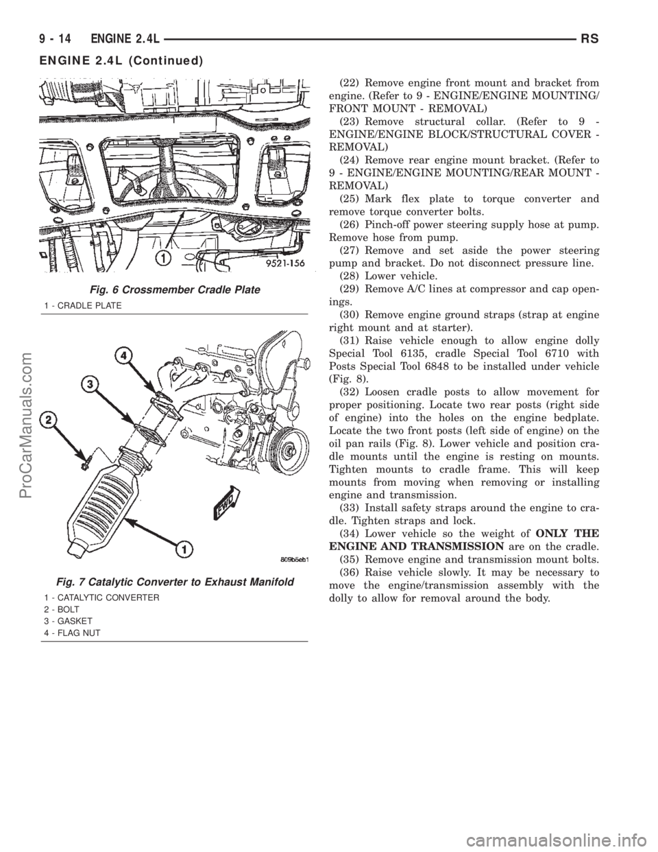
Fig. 6 Crossmember Cradle Plate
1 - CRADLE PLATE
Fig. 7 Catalytic Converter to Exhaust Manifold
1 - CATALYTIC CONVERTER
2 - BOLT
3 - GASKET
4 - FLAG NUT
9 - 14 ENGINE 2.4LRS
ENGINE 2.4L (Continued)
ProCarManuals.com
Page 1216 of 2399
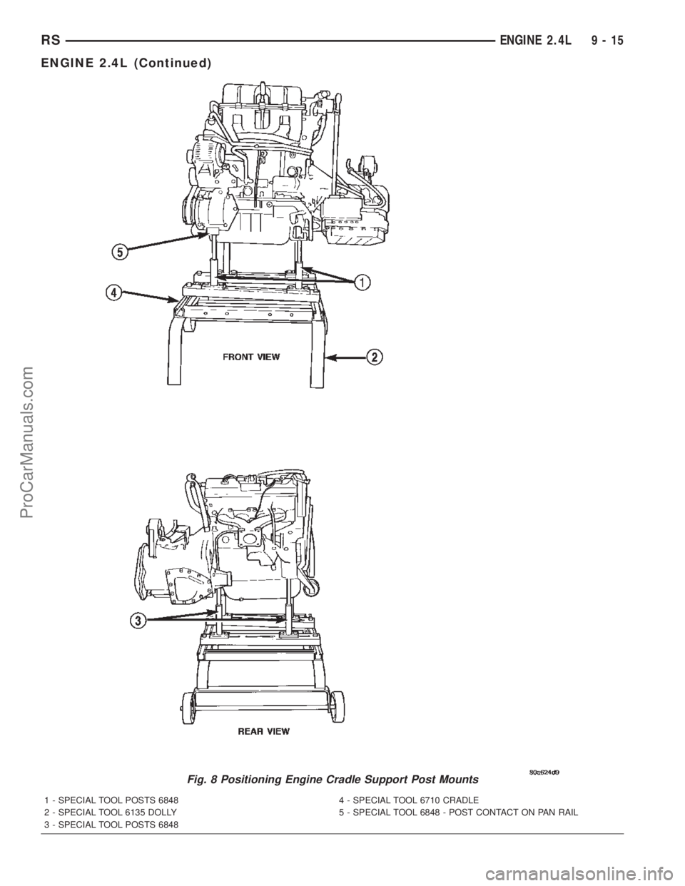
Fig. 8 Positioning Engine Cradle Support Post Mounts
1 - SPECIAL TOOL POSTS 6848 4 - SPECIAL TOOL 6710 CRADLE
2 - SPECIAL TOOL 6135 DOLLY 5 - SPECIAL TOOL 6848 - POST CONTACT ON PAN RAIL
3 - SPECIAL TOOL POSTS 6848
RSENGINE 2.4L9-15
ENGINE 2.4L (Continued)
ProCarManuals.com
Page 1217 of 2399

INSTALLATION - ENGINE ASSEMBLY
(1) Position engine and transmission assembly
under vehicle and slowly lower the vehicle over the
engine and transmission.
(2) Align engine and transmission mounts to
attaching points. Install mounting bolts at the right
(Fig. 9) and left mounts (Fig. 10).
(3) Remove safety straps.
(4) Slowly raise vehicle enough to remove the
engine dolly and cradle Special Tools 6135 and 6710.
(5) Install rear mount bracket and rear mount
through bolt. (Refer to 9 - ENGINE/ENGINE
MOUNTING/REAR MOUNT - INSTALLATION)
(6) Install the flex plate to torque converter bolts.
(7) Install structural collar. (Refer to 9 - ENGINE/
ENGINE BLOCK/STRUCTURAL COVER - INSTAL-
LATION)
(8) Install front mount bracket and front mount
through bolt. (Refer to 9 - ENGINE/ENGINE
MOUNTING/FRONT MOUNT - INSTALLATION)
(9) Connect exhaust system to manifold (Fig. 7).
(10) Install crossmember cradle plate (Fig. 6).
(11) Install new oil filter.
(12) Install power steering pump and bracket.(13) Connect power steering supply line to pump
and remove pinch-off pliers.
(14) Connect A/C compressor hoses to compressor.
(15) Install accessory drive belts. (Refer to 7 -
COOLING/ACCESSORY DRIVE/DRIVE BELTS -
INSTALLATION)
(16) Install axle shafts. (Refer to 3 - DIFFEREN-
TIAL & DRIVELINE/HALF SHAFT - INSTALLA-
TION)
(17) Install accessory drive belt splash shield.
(18) Install front wheels and tires.
(19) Remove plugs from transmission cooler hoses
and install transaxle oil cooler line service splice kit.
Refer to instructions included with kit.
(20) Connect the transaxle shift linkage and elec-
trical connectors.
(21) Connect heater hoses (Fig. 5).
(22) Install ground straps.
(23) Connect all engine and throttle body electrical
connections.
(24) Connect all vacuum lines.
(25) Connect the throttle cables.
(26) Connect the fuel line. (Refer to 14 - FUEL
SYSTEM/FUEL DELIVERY/QUICK CONNECT FIT-
TING - STANDARD PROCEDURE)
(27) Connect radiator lower and upper hoses.
(28) Install radiator fans. (Refer to 7 - COOLING/
ENGINE/RADIATOR FAN - INSTALLATION)
(29) Fill cooling system. (Refer to 7 - COOLING -
STANDARD PROCEDURE)
(30) Connect battery cables.
(31) Install air cleaner and inlet hose.
Fig. 9 RIGHT MOUNT TO RAIL AND ENGINE
1 - BOLT - MOUNT TO RAIL 68 N´m (50 ft. lbs.)
2 - BOLT - MOUNT TO ENGINE 54 N´m (40 ft. lbs.)
3 - BOLT - MOUNT TO RAIL (HORIZONTAL) 68 N´m (50 ft. lbs.)
4 - RIGHT ENGINE MOUNT
5 - RIGHT FRAME RAIL
Fig. 10 LEFT MOUNT TO FRAME BRACKET
1 - FRAME BRACKET
2 - FRAME RAIL - LEFT
3 - BOLT
4 - TRANSAXLE MOUNT
9 - 16 ENGINE 2.4LRS
ENGINE 2.4L (Continued)
ProCarManuals.com
Page 1221 of 2399
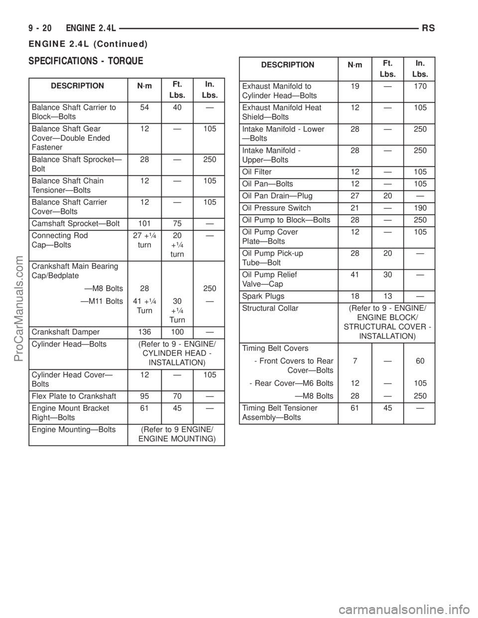
SPECIFICATIONS - TORQUE
DESCRIPTION N´mFt.
Lbs.In.
Lbs.
Balance Shaft Carrier to
BlockÐBolts54 40 Ð
Balance Shaft Gear
CoverÐDouble Ended
Fastener12 Ð 105
Balance Shaft SprocketÐ
Bolt28 Ð 250
Balance Shaft Chain
TensionerÐBolts12 Ð 105
Balance Shaft Carrier
CoverÐBolts12 Ð 105
Camshaft SprocketÐBolt 101 75 Ð
Connecting Rod
CapÐBolts27 +
1¤4
turn20
+1¤4
turnÐ
Crankshaft Main Bearing
Cap/Bedplate
ÐM8 Bolts 28 250
ÐM11 Bolts 41 +
1¤4
Turn30
+1¤4
TurnÐ
Crankshaft Damper 136 100 Ð
Cylinder HeadÐBolts (Refer to 9 - ENGINE/
CYLINDER HEAD -
INSTALLATION)
Cylinder Head CoverÐ
Bolts12 Ð 105
Flex Plate to Crankshaft 95 70 Ð
Engine Mount Bracket
RightÐBolts61 45 Ð
Engine MountingÐBolts (Refer to 9 ENGINE/
ENGINE MOUNTING)
DESCRIPTION N´mFt.
Lbs.In.
Lbs.
Exhaust Manifold to
Cylinder HeadÐBolts19 Ð 170
Exhaust Manifold Heat
ShieldÐBolts12 Ð 105
Intake Manifold - Lower
ÐBolts28 Ð 250
Intake Manifold -
UpperÐBolts28 Ð 250
Oil Filter 12 Ð 105
Oil PanÐBolts 12 Ð 105
Oil Pan DrainÐPlug 27 20 Ð
Oil Pressure Switch 21 Ð 190
Oil Pump to BlockÐBolts 28 Ð 250
Oil Pump Cover
PlateÐBolts12 Ð 105
Oil Pump Pick-up
TubeÐBolt28 20 Ð
Oil Pump Relief
ValveÐCap41 30 Ð
Spark Plugs 18 13 Ð
Structural Collar (Refer to 9 - ENGINE/
ENGINE BLOCK/
STRUCTURAL COVER -
INSTALLATION)
Timing Belt Covers
- Front Covers to Rear
CoverÐBolts7Ð60
- Rear CoverÐM6 Bolts 12 Ð 105
ÐM8 Bolts 28 Ð 250
Timing Belt Tensioner
AssemblyÐBolts61 45 Ð
9 - 20 ENGINE 2.4LRS
ENGINE 2.4L (Continued)
ProCarManuals.com
Page 1239 of 2399
(4) Tighten the bolts to 27 N´m PLUS 1/4 turn (20
ft. lbs. PLUS 1/4 turn)Do not use a torque
wrench for last step.
(5) Using a feeler gauge, check connecting rod side
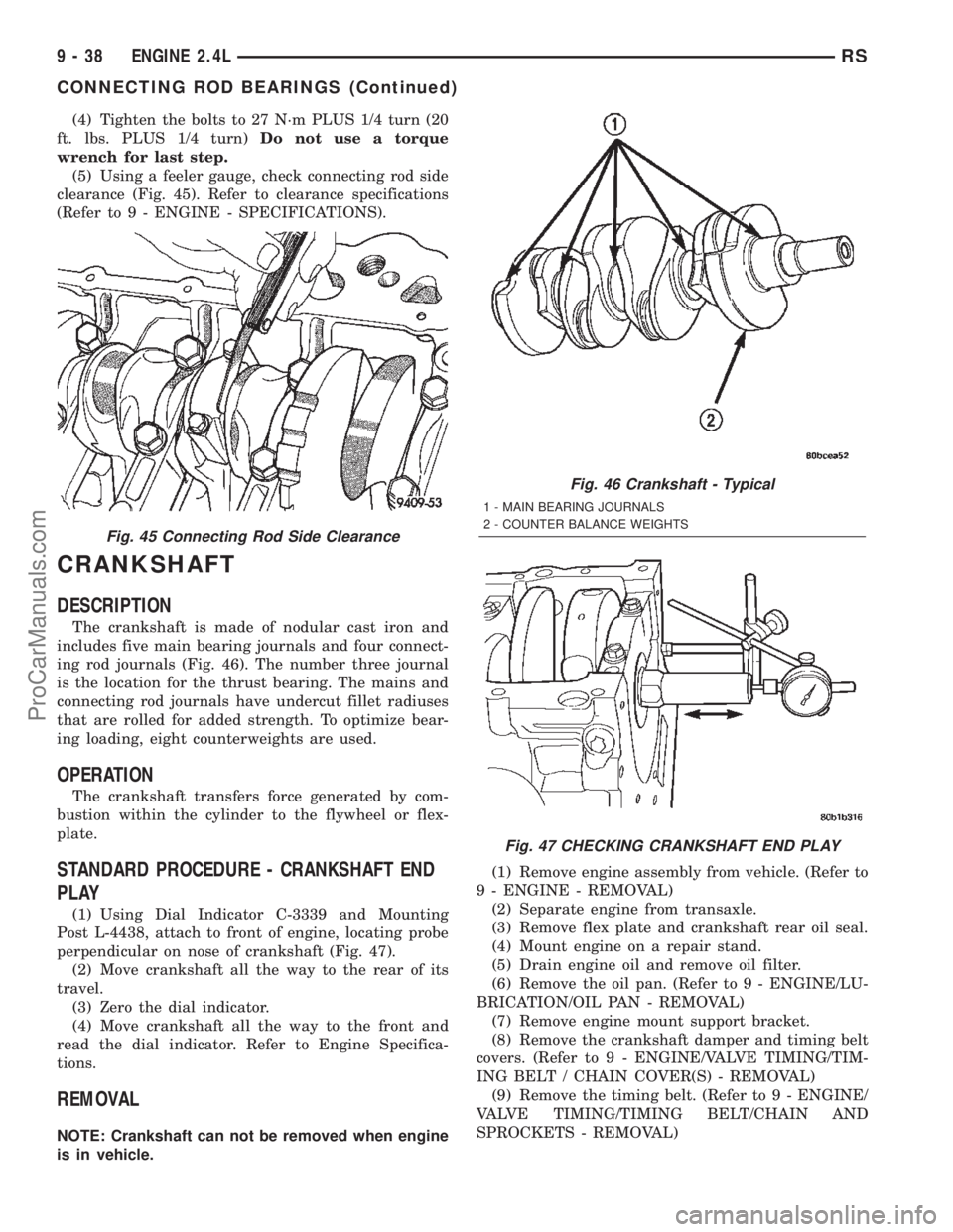
clearance (Fig. 45). Refer to clearance specifications
(Refer to 9 - ENGINE - SPECIFICATIONS).
CRANKSHAFT
DESCRIPTION
The crankshaft is made of nodular cast iron and
includes five main bearing journals and four connect-
ing rod journals (Fig. 46). The number three journal
is the location for the thrust bearing. The mains and
connecting rod journals have undercut fillet radiuses
that are rolled for added strength. To optimize bear-
ing loading, eight counterweights are used.
OPERATION
The crankshaft transfers force generated by com-
bustion within the cylinder to the flywheel or flex-
plate.
STANDARD PROCEDURE - CRANKSHAFT END
PLAY
(1) Using Dial Indicator C-3339 and Mounting
Post L-4438, attach to front of engine, locating probe
perpendicular on nose of crankshaft (Fig. 47).
(2) Move crankshaft all the way to the rear of its
travel.
(3) Zero the dial indicator.
(4) Move crankshaft all the way to the front and
read the dial indicator. Refer to Engine Specifica-
tions.
REMOVAL
NOTE: Crankshaft can not be removed when engine
is in vehicle.(1) Remove engine assembly from vehicle. (Refer to
9 - ENGINE - REMOVAL)
(2) Separate engine from transaxle.
(3) Remove flex plate and crankshaft rear oil seal.
(4) Mount engine on a repair stand.
(5) Drain engine oil and remove oil filter.
(6) Remove the oil pan. (Refer to 9 - ENGINE/LU-
BRICATION/OIL PAN - REMOVAL)
(7) Remove engine mount support bracket.
(8) Remove the crankshaft damper and timing belt
covers. (Refer to 9 - ENGINE/VALVE TIMING/TIM-
ING BELT / CHAIN COVER(S) - REMOVAL)
(9) Remove the timing belt. (Refer to 9 - ENGINE/
VALVE TIMING/TIMING BELT/CHAIN AND
SPROCKETS - REMOVAL)
Fig. 45 Connecting Rod Side Clearance
Fig. 46 Crankshaft - Typical
1 - MAIN BEARING JOURNALS
2 - COUNTER BALANCE WEIGHTS
Fig. 47 CHECKING CRANKSHAFT END PLAY
9 - 38 ENGINE 2.4LRS
CONNECTING ROD BEARINGS (Continued)
ProCarManuals.com
Page 1242 of 2399
(21) Install the timing belt front covers. (Refer to 9
- ENGINE/VALVE TIMING/TIMING BELT / CHAIN
COVER(S) - INSTALLATION)
(22) Install engine mount support bracket.
(23) Install the oil pan. (Refer to 9 - ENGINE/LU-
BRICATION/OIL PAN - INSTALLATION)
(24) Install the oil filter.
(25) Install crankshaft rear oil seal. (Refer to 9 -
ENGINE/ENGINE BLOCK/CRANKSHAFT OIL
SEAL - REAR - INSTALLATION)
(26) Install flex plate. Apply MopartLock & Seal
Adhesive to bolt threads and tighten to 95 N´m (70
ft. lbs.).
(27) Attach transaxle to engine. Tighten attaching
bolts to 101 N´m (75 ft. lbs.).
(28) Install the engine assembly. (Refer to 9 -
ENGINE - INSTALLATION)
CRANKSHAFT MAIN
BEARINGS
STANDARD PROCEDURE - MAIN BEARING -
FITTING
For crankshaft specifications (Refer to 9 - ENGINE
- SPECIFICATIONS).
CRANKSHAFT MAIN BEARINGS
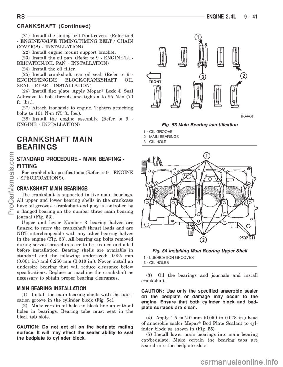
The crankshaft is supported in five main bearings.
All upper and lower bearing shells in the crankcase
have oil grooves. Crankshaft end play is controlled by
a flanged bearing on the number three main bearing
journal (Fig. 53).
Upper and lower Number 3 bearing halves are
flanged to carry the crankshaft thrust loads and are
NOT interchangeable with any other bearing halves
in the engine (Fig. 53). All bearing cap bolts removed
during service procedures are to be cleaned and oiled
before installation. Bearing shells are available in
standard and the following undersized: 0.025 mm
(0.001 in.) and 0.250 mm (0.010 in.). Never install an
undersize bearing that will reduce clearance below
specifications. Replace or machine the crankshaft as
necessary to obtain proper bearing clearances.
MAIN BEARING INSTALLATION
(1) Install the main bearing shells with the lubri-
cation groove in the cylinder block (Fig. 54).
(2) Make certain oil holes in block line up with oil
holes in bearings. Bearing tabs must seat in the
block tab slots.
CAUTION: Do not get oil on the bedplate mating
surface. It will may effect the sealer ability to seal
the bedplate to cylinder block.(3) Oil the bearings and journals and install
crankshaft.
CAUTION: Use only the specified anaerobic sealer
on the bedplate or damage may occur to the
engine. Ensure that both cylinder block and bed-
plate surfaces are clean.
(4) Apply 1.5 to 2.0 mm (0.059 to 0.078 in.) bead
of anaerobic sealer MopartBed Plate Sealant to cyl-
inder block as shown in (Fig. 55).
(5) Install lower main bearings into main bearing
cap/bedplate. Make certain the bearing tabs are
seated into the bedplate slots.
Fig. 53 Main Bearing Identification
1 - OIL GROOVE
2 - MAIN BEARINGS
3 - OIL HOLE
Fig. 54 Installing Main Bearing Upper Shell
1 - LUBRICATION GROOVES
2 - OIL HOLES
RSENGINE 2.4L9-41
CRANKSHAFT (Continued)
ProCarManuals.com
Page 1250 of 2399
STRUCTURAL COLLAR
REMOVAL
(1) Raise vehicle on hoist.
(2) Remove engine front mount bracket and front
insulator mount. (Refer to 9 - ENGINE/ENGINE
MOUNTING/FRONT MOUNT - REMOVAL)
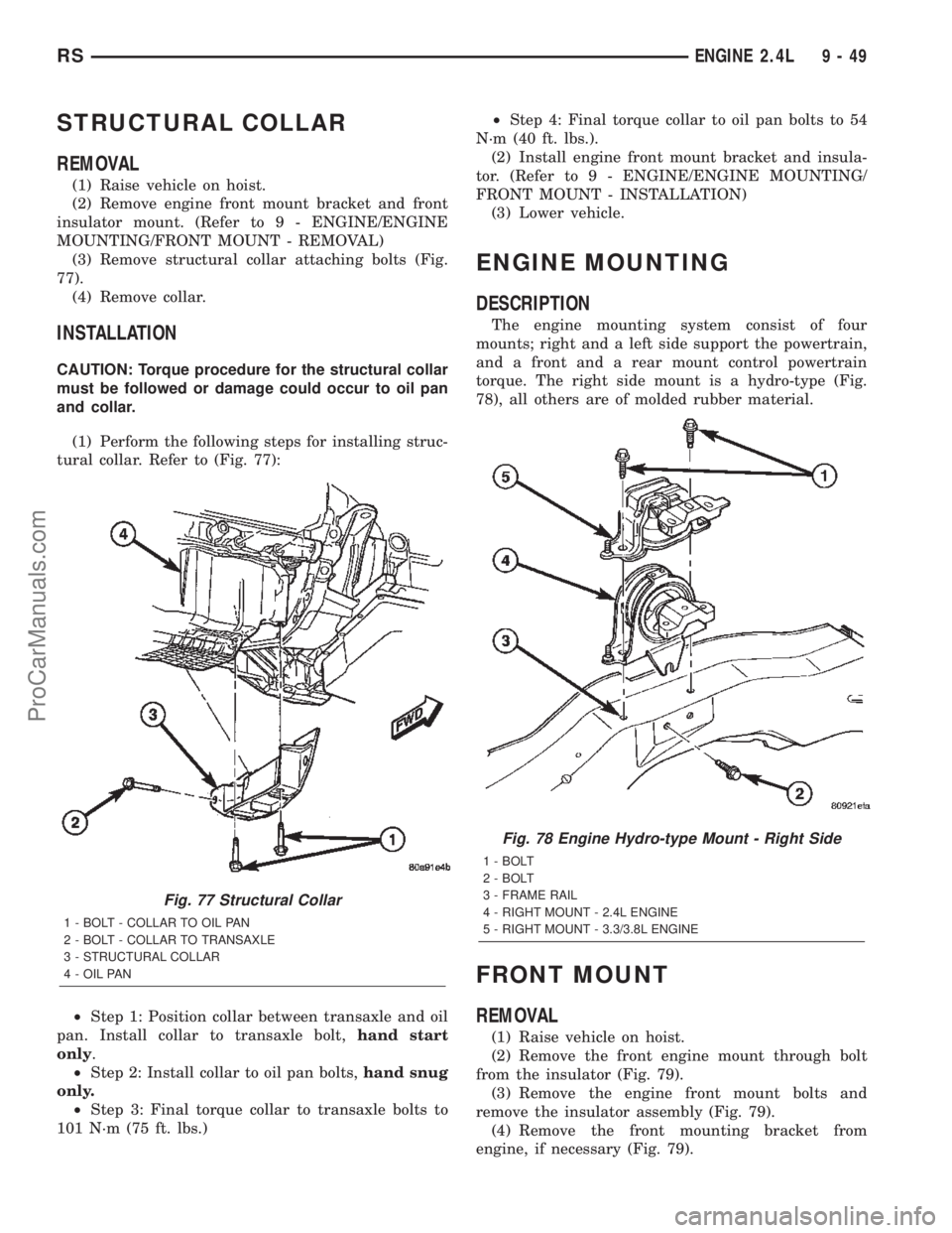
(3) Remove structural collar attaching bolts (Fig.
77).
(4) Remove collar.
INSTALLATION
CAUTION: Torque procedure for the structural collar
must be followed or damage could occur to oil pan
and collar.
(1) Perform the following steps for installing struc-
tural collar. Refer to (Fig. 77):
²Step 1: Position collar between transaxle and oil
pan. Install collar to transaxle bolt,hand start
only.
²Step 2: Install collar to oil pan bolts,hand snug
only.
²Step 3: Final torque collar to transaxle bolts to
101 N´m (75 ft. lbs.)²Step 4: Final torque collar to oil pan bolts to 54
N´m (40 ft. lbs.).
(2) Install engine front mount bracket and insula-
tor. (Refer to 9 - ENGINE/ENGINE MOUNTING/
FRONT MOUNT - INSTALLATION)
(3) Lower vehicle.
ENGINE MOUNTING
DESCRIPTION
The engine mounting system consist of four
mounts; right and a left side support the powertrain,
and a front and a rear mount control powertrain
torque. The right side mount is a hydro-type (Fig.
78), all others are of molded rubber material.
FRONT MOUNT
REMOVAL
(1) Raise vehicle on hoist.
(2) Remove the front engine mount through bolt
from the insulator (Fig. 79).
(3) Remove the engine front mount bolts and
remove the insulator assembly (Fig. 79).
(4) Remove the front mounting bracket from
engine, if necessary (Fig. 79).
Fig. 77 Structural Collar
1 - BOLT - COLLAR TO OIL PAN
2 - BOLT - COLLAR TO TRANSAXLE
3 - STRUCTURAL COLLAR
4 - OIL PAN
Fig. 78 Engine Hydro-type Mount - Right Side
1 - BOLT
2 - BOLT
3 - FRAME RAIL
4 - RIGHT MOUNT - 2.4L ENGINE
5 - RIGHT MOUNT - 3.3/3.8L ENGINE
RSENGINE 2.4L9-49
ProCarManuals.com