torque CHRYSLER VOYAGER 1996 Service Manual
[x] Cancel search | Manufacturer: CHRYSLER, Model Year: 1996, Model line: VOYAGER, Model: CHRYSLER VOYAGER 1996Pages: 1938, PDF Size: 55.84 MB
Page 1410 of 1938

(a) Remove the throttle body from engine.
(b) While holding the throttle open, spray the
entire throttle body bore and the manifold side of
the throttle plate with Mopar Parts Cleaner.Only
use Mopar Parts Cleaner to clean the throttle
body.
(c) Using a soft scuff pad, clean the top and bot-
tom of throttle body bore and the edges and mani-
fold side of the throttle blade.The edges of the
throttle blade and portions of the throttle
bore that are closest to the throttle blade
when closed, must be free of deposits.
(d) Use compressed air to dry the throttle body.
(e) Inspect throttle body for foreign material.
(f) Install throttle body on manifold.
(g) Repeat steps 1 through 14. If the minimum
air flow is still not within specifications, the prob-
lem is not caused by the throttle body.
(12) Shut off engine.
(13) Remove Air Metering Orifice 6457. Install
purge hose.
(14) Remove cap from PCV valve. Connect hose to
PCV valve.
(15) Remove DRB scan tool.SPECIFICATIONS
TORQUE
DESCRIPTION TORQUE
Air Cleaner Wingnut.........1.5N´m(15in.lbs.)
Air Cleaner Mount. Stud-To-Thrott. Body . . 10 N´m
(90 in. lbs.)
Crankshaft Position Sensor Mounting Bolts . . 8 N´m
(70 in. lbs.)
Engine Coolant Temperature Sensor......18N´m
(165 in. lbs.)
IAC Motor-To-Throttle Body Bolts.........7N´m
(60 in. lbs.)
MAP/IAT Sensor.............2N´m(20in.lbs.)
MAP/IAT Sensor.............3N´m(30in.lbs.)
Oxygen Sensor..............28N´m(20ft.lbs.)
Powertrain Control Module
(PCM) Mounting Screws.....4N´m(35in.lbs.)
Throttle Cable Cover........4.5N´m(40in.lbs.).
Throttle Body Mounting Bolts...........23N´m
(200 in. lbs.)
Throttle Position Sensor Mounting Screws . . . 2 N´m
(20 in. lbs.)
Vehicle Speed Sensor Mounting Bolt......2.2N´m
(20 in. lbs.)
14 - 42 FUEL SYSTEMÐ2.5L DIESEL ENGINE/2.0L GAS ENGINENS/GS
DIAGNOSIS AND TESTING (Continued)
Page 1411 of 1938

FUEL INJECTION SYSTEMÐ2.5L DIESEL ENGINE
INDEX
page page
GENERAL INFORMATION
INTRODUCTION....................... 43
DESCRIPTION AND OPERATION
AIR CONDITIONING (A/C) CONTROLSÐ
PCM INPUTS........................ 47
AIR CONDITIONING RELAYÐPCM OUTPUT . . 48
BATTERY VOLTAGEÐPCM INPUT.......... 45
BOOST PRESSURE SENSOR............. 45
BRAKE SWITCHÐPCM INPUT............. 47
DATA LINK CONNECTORÐ
PCM INPUT AND OUTPUT.............. 47
DIESEL PCM RELAYÐPCM INPUT......... 48
ENGINE COOLANT GAUGEÐPCM OUTPUT . . 48
ENGINE COOLANT TEMPERATURE SENSORÐ
PCM INPUT......................... 46
ENGINE OIL PRESSURE GAUGEÐ
PCM OUTPUT........................ 48
ENGINE SPEED SENSORÐPCM INPUT..... 46
EXHAUST GAS RECIRCULATION (EGR)
SOLENOIDÐPCM OUTPUT............. 50
FIVE VOLT POWERÐPCM OUTPUT........ 48
FUEL INJECTOR SENSORÐGROUND...... 46
FUEL TIMING SOLENOIDÐPCM OUTPUT.... 48
GLOW PLUG LAMPÐPCM OUTPUT........ 48
GLOW PLUG RELAYÐPCM OUTPUT....... 49
GLOW PLUGS......................... 49
IGNITION CIRCUIT SENSEÐPCM INPUT.... 45
NEEDLE MOVEMENT OR INSTRUMENTED
FIRST INJECTORÐPCM INPUT.......... 45
POWER GROUND...................... 45
POWERTRAIN CONTROL MODULE (PCM) . . . 44
SENSOR RETURNÐPCM INPUT (ANALOG
GROUND)........................... 45SIGNAL GROUNDÐPCM INPUT........... 45
SPEED CONTROLÐPCM INPUTS.......... 48
SPEED CONTROLÐPCM OUTPUTS........ 48
START SIGNALÐPCM INPUT............. 45
TACHOMETERÐPCM OUTPUT............ 49
VEHICLE SPEED SENSORÐPCM INPUT.... 47
VEHICLE THEFT ALARM................. 45
DIAGNOSIS AND TESTING
BOOST PRESSURE SENSOR............. 53
DIAGNOSTIC TROUBLE CODES........... 53
DIESEL DIAGNOSTICS.................. 50
DIESEL PCM RELAY TEST............... 50
ENGINE COOLANT TEMPERATURE
SENSOR TEST....................... 50
ENGINE SPEED SENSOR TEST........... 50
GLOW PLUG RELAY TEST............... 51
GLOW PLUG TEST..................... 51
RELAYSÐOPERATION/TESTING........... 52
VEHICLE SPEED SENSOR TEST........... 53
REMOVAL AND INSTALLATION
A/C CLUTCH RELAY.................... 53
DIESEL PCM RELAY.................... 53
ENGINE COOLANT TEMPERATURE
SENSOR............................ 54
ENGINE SPEED SENSOR................ 53
GLOW PLUG RELAY.................... 55
GLOW PLUGS......................... 54
POWERTRAIN CONTROL MODULE (PCM) . . . 55
VEHICLE SPEED SENSOR............... 55
SPECIFICATIONS
GLOW PLUG CURRENT DRAW............ 56
TORQUE CHARTÐ2.5L DIESEL............ 57
GENERAL INFORMATION
INTRODUCTION
This section will cover components either regulated
or controlled by the Powertrain Control Module
(PCM). The fuel heater relay, fuel heater and fuel
gauge are not operated by the PCM. These compo-
nents are controlled by the ignition (key) switch. All
other fuel system electrical components necessary to
operate the engine are controlled or regulated by the
PCM. Refer to the following PCM description for
more information.
Certain fuel system component failures may cause
a no start, or prevent the engine from running. It is
important to know that the PCM has a featurewhere, if possible, it will ignore the failed sensor, set
a code related to the sensor, and operate the engine
in a ªLimp Homeº mode. When the PCM is operating
in a ªLimp Homeº mode, the Diesel Glow Plug lamp
on the instrument panel will be constantly illumi-
nated, and the engine will most likely have a notice-
able loss of performance. An example of this would be
an Accelerator Pedal Position Sensor failure, and in
that situation, the engine would run at a constant
1100 RPM, regardless of the actual position of the
pedal. This is the most extreme of the three ªLimp
Homeº modes.
In addition to indicating that the glow plugs are
hot enough to start combustion, the Glow Plug Lamp
is also used in the diagnosis of the PCM, and when
NS/GSFUEL SYSTEMÐ2.5L DIESEL ENGINE/2.0L GAS ENGINE 14 - 43
Page 1422 of 1938

(2) Remove the sensor mounting bolts.
(3) Remove the sensor.
INSTALLATION
(1) Install the sensor flush against the opening in
the transmission housing.
(2) Install and tighten the sensor mounting bolt to
19 N´m (14 ft. lbs.) torque.
(3) Connect the electrical connector to the sensor.
ENGINE COOLANT TEMPERATURE SENSOR
The sensor is located on the side of cylinder head
near the rear of fuel injection pump (Fig. 19).
REMOVAL
WARNING: HOT, PRESSURIZED COOLANT CAN
CAUSE INJURY BY SCALDING. COOLING SYSTEM
MUST BE PARTIALLY DRAINED BEFORE REMOV-
ING THE COOLANT TEMPERATURE SENSOR.
REFER TO GROUP 7, COOLING.
(1) Partially drain cooling system. Refer to Group
7, Cooling.
(2) Disconnect electrical connector from sensor.
(3) Remove sensor from cylinder head.
INSTALLATION
(1) Install a new copper gasket to sensor.
(2) Install sensor to cylinder head.
(3) Tighten sensor to 18 N´m (13 ft. lbs.) torque.
(4) Connect electrical connector to sensor.
(5) Replace any lost engine coolant. Refer to Group
7, Cooling System.
GLOW PLUGS
The glow plugs are located above each fuel injector
(Fig. 20). Four individual plugs are used.
REMOVAL
(1) Disconnect the negative battery cable at the
battery.
(2) Clean the area around the glow plug with com-
pressed air before removal.
(3) Disconnect electrical connector (Fig. 21) at glow
plug.
(4) Remove the glow plug (Fig. 20) from cylinder
head.
Fig. 18 Engine Speed SensorFig. 19 Engine Coolant Temperature Sensor
Location
Fig. 20 Glow Plug
14 - 54 FUEL SYSTEMÐ2.5L DIESEL ENGINE/2.0L GAS ENGINENS/GS
REMOVAL AND INSTALLATION (Continued)
Page 1423 of 1938

INSTALLATION
(1) Apply high±temperature anti±seize compound
to glow plug threads before installation
(2) Install the glow plug into the cylinder head.
Tighten to 23 N´m (203 in. lbs.) torque.
(3) Connect battery cable to battery.
GLOW PLUG RELAY
The glow plug relay is located in the engine com-
partment on the left±inner fender (Fig. 22).
REMOVAL
(1) Disconnect the negative battery cable at the
battery.
(2) Remove relay mounting bolt.(3) Disconnect electrical connector at relay and
remove relay.
INSTALLATION
(1) Check condition of electrical connector for dam-
age or corrosion. Repair as necessary.
(2) Install electrical connector to relay.
(3) Install relay to inner fender.
(4) Connect battery cable to battery.
POWERTRAIN CONTROL MODULE (PCM)
The PCM is mounted to a bracket located in the
center consule in front of the air bag module (Fig.
23).
REMOVAL
(1) Disconnect the negative battery cable at the
battery.
(2) Loosen the 68±Way connector (Fig. 23). The
electrical connector has a sliding bar which moves
inward to lock or outward to unlock.
(3) Remove the electrical connector by pulling
straight out.
(4) Remove PCM.
INSTALLATION
(1) After the PCM electrical connector has been
separated from the PCM, inspect the pins for corro-
sion, being spread apart, bent or misaligned. Also
inspect the pin heights in the connector. If the pin
heights are different, this would indicate a pin has
separated from the connector. Repair as necessary.
(2) Engage 68±way connector into PCM. Move
slide bar to lock connector.
(3) Connect negative cable to battery.
VEHICLE SPEED SENSOR
The vehicle speed sensor (Fig. 24) is located on the
extension housing of the transmission.
Fig. 21 Glow Plug Electrical Connector
Fig. 22 Glow Plug Relay Location
Fig. 23 PCM Location
NS/GSFUEL SYSTEMÐ2.5L DIESEL ENGINE/2.0L GAS ENGINE 14 - 55
REMOVAL AND INSTALLATION (Continued)
Page 1425 of 1938
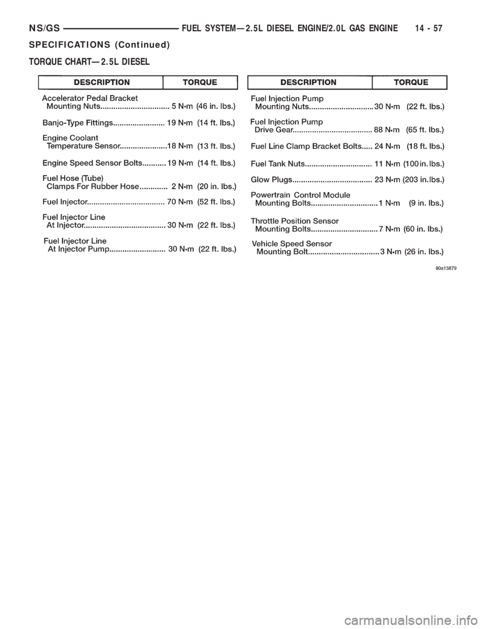
TORQUE CHARTÐ2.5L DIESEL
NS/GSFUEL SYSTEMÐ2.5L DIESEL ENGINE/2.0L GAS ENGINE 14 - 57
SPECIFICATIONS (Continued)
Page 1428 of 1938
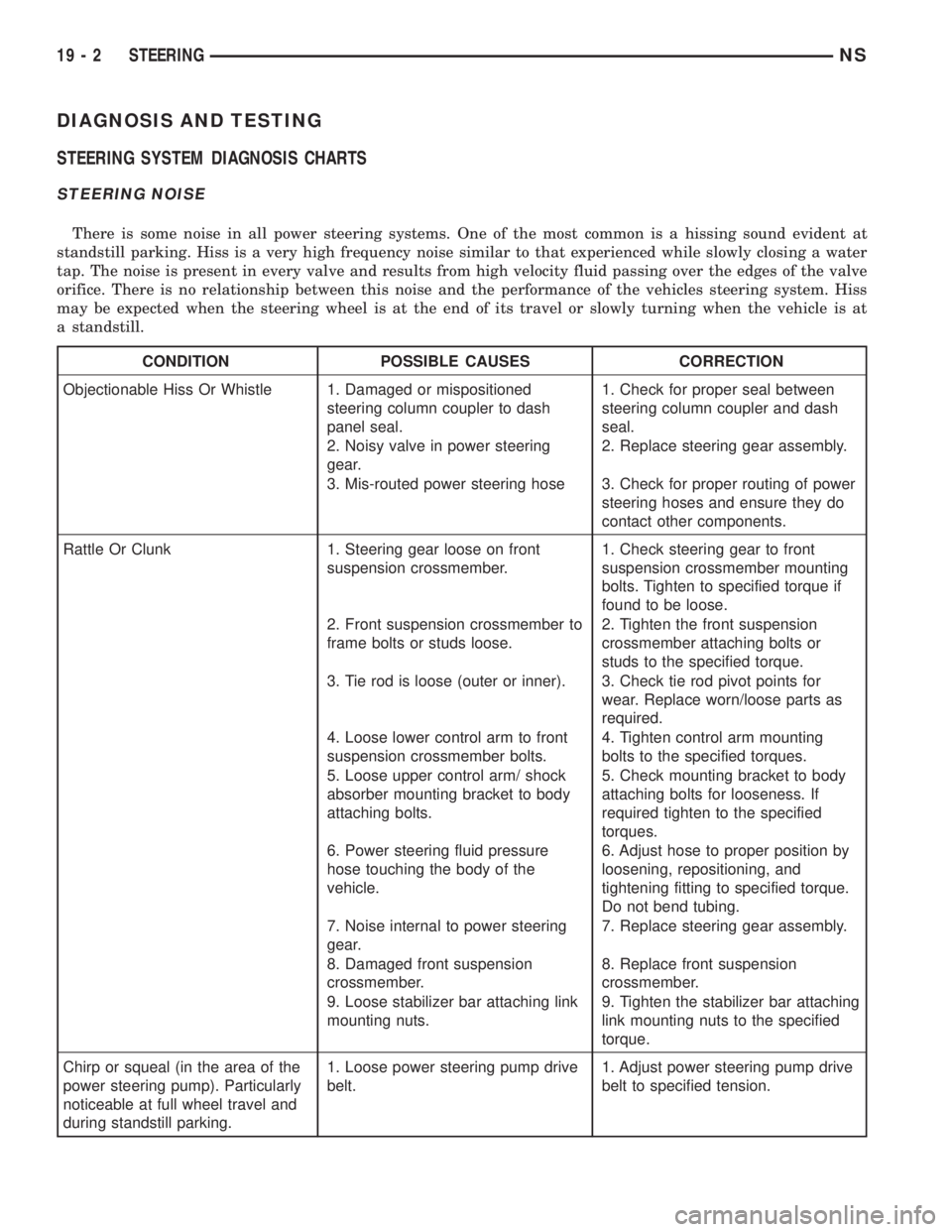
DIAGNOSIS AND TESTING
STEERING SYSTEM DIAGNOSIS CHARTS
STEERING NOISE
There is some noise in all power steering systems. One of the most common is a hissing sound evident at
standstill parking. Hiss is a very high frequency noise similar to that experienced while slowly closing a water
tap. The noise is present in every valve and results from high velocity fluid passing over the edges of the valve
orifice. There is no relationship between this noise and the performance of the vehicles steering system. Hiss
may be expected when the steering wheel is at the end of its travel or slowly turning when the vehicle is at
a standstill.
CONDITION POSSIBLE CAUSES CORRECTION
Objectionable Hiss Or Whistle 1. Damaged or mispositioned
steering column coupler to dash
panel seal.1. Check for proper seal between
steering column coupler and dash
seal.
2. Noisy valve in power steering
gear.2. Replace steering gear assembly.
3. Mis-routed power steering hose 3. Check for proper routing of power
steering hoses and ensure they do
contact other components.
Rattle Or Clunk 1. Steering gear loose on front
suspension crossmember.1. Check steering gear to front
suspension crossmember mounting
bolts. Tighten to specified torque if
found to be loose.
2. Front suspension crossmember to
frame bolts or studs loose.2. Tighten the front suspension
crossmember attaching bolts or
studs to the specified torque.
3. Tie rod is loose (outer or inner). 3. Check tie rod pivot points for
wear. Replace worn/loose parts as
required.
4. Loose lower control arm to front
suspension crossmember bolts.4. Tighten control arm mounting
bolts to the specified torques.
5. Loose upper control arm/ shock
absorber mounting bracket to body
attaching bolts.5. Check mounting bracket to body
attaching bolts for looseness. If
required tighten to the specified
torques.
6. Power steering fluid pressure
hose touching the body of the
vehicle.6. Adjust hose to proper position by
loosening, repositioning, and
tightening fitting to specified torque.
Do not bend tubing.
7. Noise internal to power steering
gear.7. Replace steering gear assembly.
8. Damaged front suspension
crossmember.8. Replace front suspension
crossmember.
9. Loose stabilizer bar attaching link
mounting nuts.9. Tighten the stabilizer bar attaching
link mounting nuts to the specified
torque.
Chirp or squeal (in the area of the
power steering pump). Particularly
noticeable at full wheel travel and
during standstill parking.1. Loose power steering pump drive
belt.1. Adjust power steering pump drive
belt to specified tension.
19 - 2 STEERINGNS
Page 1430 of 1938
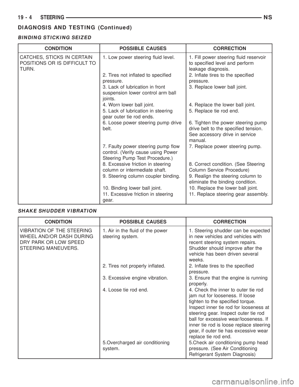
BINDING STICKING SEIZED
SHAKE SHUDDER VIBRATION
CONDITION POSSIBLE CAUSES CORRECTION
CATCHES, STICKS IN CERTAIN
POSITIONS OR IS DIFFICULT TO
TURN.1. Low power steering fluid level. 1. Fill power steering fluid reservoir
to specified level and perform
leakage diagnosis.
2. Tires not inflated to specified
pressure.2. Inflate tires to the specified
pressure.
3. Lack of lubrication in front
suspension lower control arm ball
joints.3. Replace lower ball joint.
4. Worn lower ball joint. 4. Replace the lower ball joint.
5. Lack of lubrication in steering
gear outer tie rod ends.5. Replace tie rod end.
6. Loose power steering pump drive
belt.6. Tighten the power steering pump
drive belt to the specified tension.
See accessory drive in service
manual.
7. Faulty power steering pump flow
control. (Verify cause using Power
Steering Pump Test Procedure.)7. Replace power steering pump.
8. Excessive friction in steering
column or intermediate shaft.8. Correct condition. (See Steering
Column Service Procedure)
9. Steering column coupler binding. 9. Realign the steering column to
eliminate the binding condition.
10. Binding lower ball joint. 10. Replace the lower ball joint.
11. Excessive friction in steering
gear.11. Replace steering gear assembly.
CONDITION POSSIBLE CAUSES CORRECTION
VIBRATION OF THE STEERING
WHEEL AND/OR DASH DURING
DRY PARK OR LOW SPEED
STEERING MANEUVERS.1. Air in the fluid of the power
steering system.1. Steering shudder can be expected
in new vehicles and vehicles with
recent steering system repairs.
Shudder should improve after the
vehicle has been driven several
weeks.
2. Tires not properly inflated. 2. Inflate tires to the specified
pressure.
3. Excessive engine vibration. 3. Ensure that the engine is running
properly.
4. Loose tie rod end. 4. Check the inner to outer tie rod
jam nut for looseness. If loose
tighten to the specified torque.
Inspect inner tie rod for looseness at
steering gear. Inspect outer tie rod
ball for excessive wear/looseness. If
inner tie rod is loose replace steering
gear, if outer tie has excessive wear
replace tie rod end.
5.Overcharged air conditioning
system.5.Check air conditioning pump head
pressure. (See Air Conditioning
Refrigerant System Diagnosis)
19 - 4 STEERINGNS
DIAGNOSIS AND TESTING (Continued)
Page 1432 of 1938
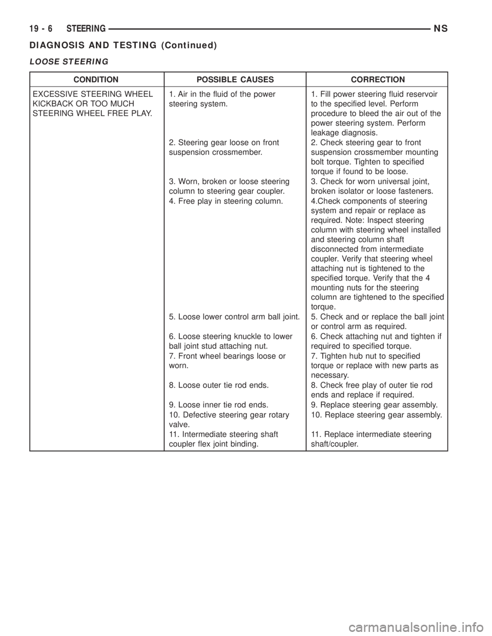
LOOSE STEERING
CONDITION POSSIBLE CAUSES CORRECTION
EXCESSIVE STEERING WHEEL
KICKBACK OR TOO MUCH
STEERING WHEEL FREE PLAY.1. Air in the fluid of the power
steering system.1. Fill power steering fluid reservoir
to the specified level. Perform
procedure to bleed the air out of the
power steering system. Perform
leakage diagnosis.
2. Steering gear loose on front
suspension crossmember.2. Check steering gear to front
suspension crossmember mounting
bolt torque. Tighten to specified
torque if found to be loose.
3. Worn, broken or loose steering
column to steering gear coupler.3. Check for worn universal joint,
broken isolator or loose fasteners.
4. Free play in steering column. 4.Check components of steering
system and repair or replace as
required. Note: Inspect steering
column with steering wheel installed
and steering column shaft
disconnected from intermediate
coupler. Verify that steering wheel
attaching nut is tightened to the
specified torque. Verify that the 4
mounting nuts for the steering
column are tightened to the specified
torque.
5. Loose lower control arm ball joint. 5. Check and or replace the ball joint
or control arm as required.
6. Loose steering knuckle to lower
ball joint stud attaching nut.6. Check attaching nut and tighten if
required to specified torque.
7. Front wheel bearings loose or
worn.7. Tighten hub nut to specified
torque or replace with new parts as
necessary.
8. Loose outer tie rod ends. 8. Check free play of outer tie rod
ends and replace if required.
9. Loose inner tie rod ends. 9. Replace steering gear assembly.
10. Defective steering gear rotary
valve.10. Replace steering gear assembly.
11. Intermediate steering shaft
coupler flex joint binding.11. Replace intermediate steering
shaft/coupler.
19 - 6 STEERINGNS
DIAGNOSIS AND TESTING (Continued)
Page 1433 of 1938
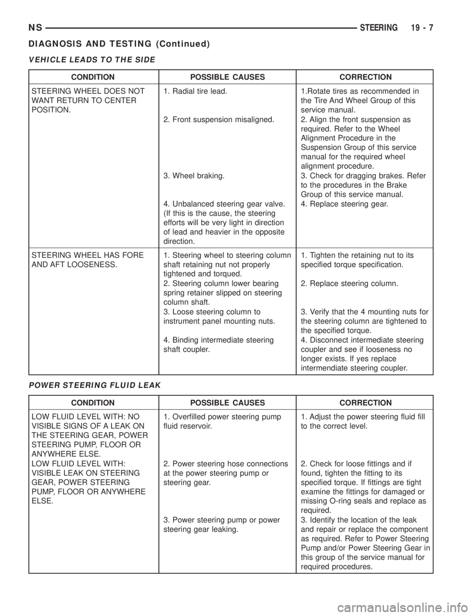
VEHICLE LEADS TO THE SIDE
POWER STEERING FLUID LEAK
CONDITION POSSIBLE CAUSES CORRECTION
STEERING WHEEL DOES NOT
WANT RETURN TO CENTER
POSITION.1. Radial tire lead. 1.Rotate tires as recommended in
the Tire And Wheel Group of this
service manual.
2. Front suspension misaligned. 2. Align the front suspension as
required. Refer to the Wheel
Alignment Procedure in the
Suspension Group of this service
manual for the required wheel
alignment procedure.
3. Wheel braking. 3. Check for dragging brakes. Refer
to the procedures in the Brake
Group of this service manual.
4. Unbalanced steering gear valve.
(If this is the cause, the steering
efforts will be very light in direction
of lead and heavier in the opposite
direction.4. Replace steering gear.
STEERING WHEEL HAS FORE
AND AFT LOOSENESS.1. Steering wheel to steering column
shaft retaining nut not properly
tightened and torqued.1. Tighten the retaining nut to its
specified torque specification.
2. Steering column lower bearing
spring retainer slipped on steering
column shaft.2. Replace steering column.
3. Loose steering column to
instrument panel mounting nuts.3. Verify that the 4 mounting nuts for
the steering column are tightened to
the specified torque.
4. Binding intermediate steering
shaft coupler.4. Disconnect intermediate steering
coupler and see if looseness no
longer exists. If yes replace
intermendiate steering coupler.
CONDITION POSSIBLE CAUSES CORRECTION
LOW FLUID LEVEL WITH: NO
VISIBLE SIGNS OF A LEAK ON
THE STEERING GEAR, POWER
STEERING PUMP, FLOOR OR
ANYWHERE ELSE.1. Overfilled power steering pump
fluid reservoir.1. Adjust the power steering fluid fill
to the correct level.
LOW FLUID LEVEL WITH:
VISIBLE LEAK ON STEERING
GEAR, POWER STEERING
PUMP, FLOOR OR ANYWHERE
ELSE.2. Power steering hose connections
at the power steering pump or
steering gear.2. Check for loose fittings and if
found, tighten the fitting to its
specified torque. If fittings are tight
examine the fittings for damaged or
missing O-ring seals and replace as
required.
3. Power steering pump or power
steering gear leaking.3. Identify the location of the leak
and repair or replace the component
as required. Refer to Power Steering
Pump and/or Power Steering Gear in
this group of the service manual for
required procedures.
NSSTEERING 19 - 7
DIAGNOSIS AND TESTING (Continued)
Page 1435 of 1938
POWER STEERING PUMP
INDEX
page page
DESCRIPTION AND OPERATION
POWER STEERING PUMP OPERATION....... 9
DIAGNOSIS AND TESTING
POWER STEERING PUMP FLOW RATE AND
PRESSURE TEST....................... 9
SERVICE PROCEDURES
POWER STEERING PUMP INITIAL
OPERATION.......................... 10
POWER STEERING SYSTEM FLUID LEVEL
CHECK.............................. 10
REMOVAL AND INSTALLATION
2.4 LITER POWER STEERING PUMP......... 11
3.0 LITER POWER STEERING PUMP........ 13
3.3/3.8 LITER POWER STEERING PUMP...... 16
POWER STEERING FLUID PRESSURE HOSE . . 19POWER STEERING FLUID RESERVOIR TO
PUMP SUPPLY HOSE................... 18
POWER STEERING FLUID RETURN HOSE.... 21
REMOTE POWER STEERING FLUID
RESERVOIR.......................... 22
DISASSEMBLY AND ASSEMBLY
POWER STEERING PUMP FLOW CONTROL
VALVE SEAL.......................... 23
POWER STEERING PUMP PULLEY.......... 23
SPECIFICATIONS
POWER STEERING PUMP FASTENER
TORQUE SPECIFICATIONS.............. 24
POWER STEERING SYSTEM
SPECIFICATIONS...................... 24
SPECIAL TOOLS
POWER STEERING PUMP................. 25
DESCRIPTION AND OPERATION
POWER STEERING PUMP OPERATION
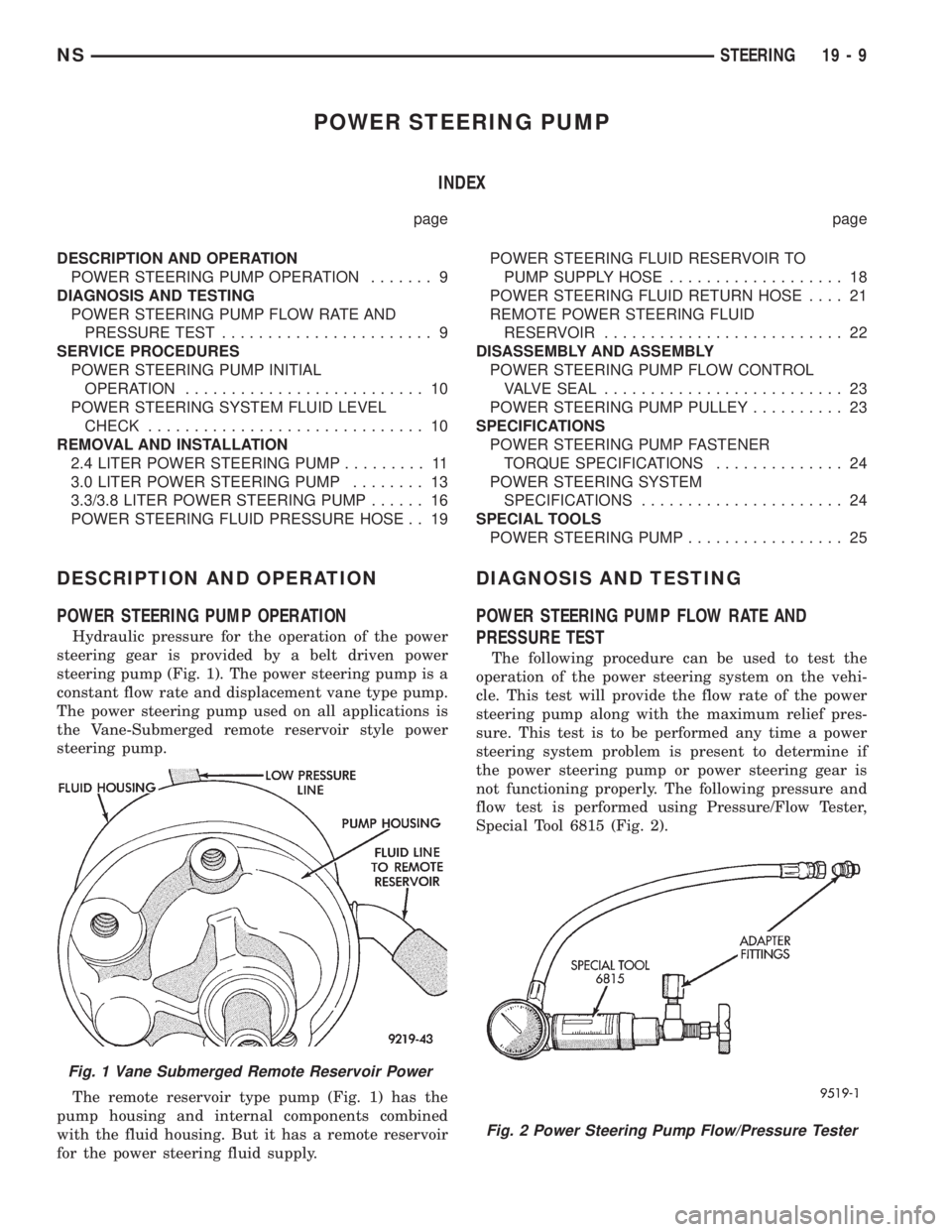
Hydraulic pressure for the operation of the power
steering gear is provided by a belt driven power
steering pump (Fig. 1). The power steering pump is a
constant flow rate and displacement vane type pump.
The power steering pump used on all applications is
the Vane-Submerged remote reservoir style power
steering pump.
The remote reservoir type pump (Fig. 1) has the
pump housing and internal components combined
with the fluid housing. But it has a remote reservoir
for the power steering fluid supply.
DIAGNOSIS AND TESTING
POWER STEERING PUMP FLOW RATE AND
PRESSURE TEST
The following procedure can be used to test the
operation of the power steering system on the vehi-
cle. This test will provide the flow rate of the power
steering pump along with the maximum relief pres-
sure. This test is to be performed any time a power
steering system problem is present to determine if
the power steering pump or power steering gear is
not functioning properly. The following pressure and
flow test is performed using Pressure/Flow Tester,
Special Tool 6815 (Fig. 2).
Fig. 1 Vane Submerged Remote Reservoir Power
Fig. 2 Power Steering Pump Flow/Pressure Tester
NSSTEERING 19 - 9