torque CHRYSLER VOYAGER 1996 Service Manual
[x] Cancel search | Manufacturer: CHRYSLER, Model Year: 1996, Model line: VOYAGER, Model: CHRYSLER VOYAGER 1996Pages: 1938, PDF Size: 55.84 MB
Page 1358 of 1938
REMOVAL AND INSTALLATION
THROTTLE BODY
REMOVAL
(1) Disconnect negative cable from battery cable.
(2) Remove air inlet to throttle body hose clamp.
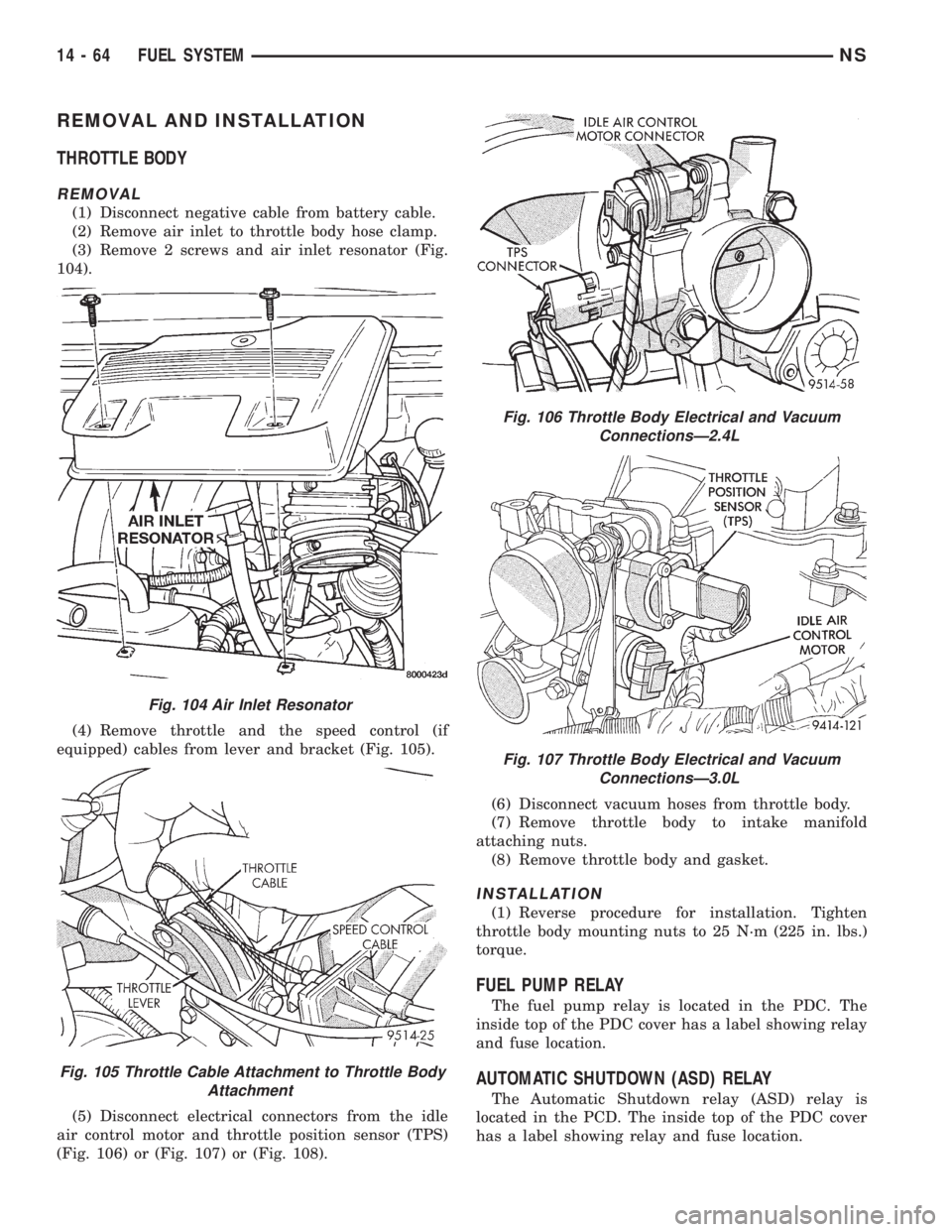
(3) Remove 2 screws and air inlet resonator (Fig.
104).
(4) Remove throttle and the speed control (if
equipped) cables from lever and bracket (Fig. 105).
(5) Disconnect electrical connectors from the idle
air control motor and throttle position sensor (TPS)
(Fig. 106) or (Fig. 107) or (Fig. 108).(6) Disconnect vacuum hoses from throttle body.
(7) Remove throttle body to intake manifold
attaching nuts.
(8) Remove throttle body and gasket.
INSTALLATION
(1) Reverse procedure for installation. Tighten
throttle body mounting nuts to 25 N´m (225 in. lbs.)
torque.
FUEL PUMP RELAY
The fuel pump relay is located in the PDC. The
inside top of the PDC cover has a label showing relay
and fuse location.
AUTOMATIC SHUTDOWN (ASD) RELAY
The Automatic Shutdown relay (ASD) relay is
located in the PCD. The inside top of the PDC cover
has a label showing relay and fuse location.
Fig. 104 Air Inlet Resonator
Fig. 105 Throttle Cable Attachment to Throttle Body
Attachment
Fig. 106 Throttle Body Electrical and Vacuum
ConnectionsÐ2.4L
Fig. 107 Throttle Body Electrical and Vacuum
ConnectionsÐ3.0L
14 - 64 FUEL SYSTEMNS
Page 1359 of 1938
THROTTLE POSITION SENSOR
REMOVAL
(1) Disconnect negative cable from battery.
(2) Remove electrical connector from throttle posi-
tion sensor.
(3) Remove throttle position sensor mounting
screws.
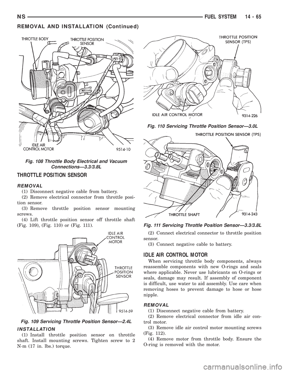
(4) Lift throttle position sensor off throttle shaft
(Fig. 109), (Fig. 110) or (Fig. 111).
INSTALLATION
(1) Install throttle position sensor on throttle
shaft. Install mounting screws. Tighten screw to 2
N´m (17 in. lbs.) torque.(2) Connect electrical connector to throttle position
sensor.
(3) Connect negative cable to battery.
IDLE AIR CONTROL MOTOR
When servicing throttle body components, always
reassemble components with new O-rings and seals
where applicable. Never use lubricants on O-rings or
seals, damage may result. If assembly of component
is difficult, use water to aid assembly. Use care when
removing hoses to prevent damage to hose or hose
nipple.
REMOVAL
(1) Disconnect negative cable from battery.
(2) Remove electrical connector from idle air con-
trol motor.
(3) Remove idle air control motor mounting screws
(Fig. 112).
(4) Remove motor from throttle body. Ensure the
O-ring is removed with the motor.
Fig. 108 Throttle Body Electrical and Vacuum
ConnectionsÐ3.3/3.8L
Fig. 109 Servicing Throttle Position SensorÐ2.4L
Fig. 110 Servicing Throttle Position SensorÐ3.0L
Fig. 111 Servicing Throttle Position SensorÐ3.3/3.8L
NSFUEL SYSTEM 14 - 65
REMOVAL AND INSTALLATION (Continued)
Page 1360 of 1938
INSTALLATION
(1) The new idle air control motor has a new
O-ring installed on it. If pintle measures more than 1
inch (25 mm) it must be retracted. Use the DRB Idle
Air Control Motor Open/Close Test to retract the
pintle (battery must be connected.)
(2) Carefully place idle air control motor into
throttle body.
(3) Install mounting screws. Tighten screws to 2
N´m (17 in. lbs.) torque.
(4) Connect electrical connector to idle air control
motor.
(5) Connect negative cable to battery.
MANIFOLD ABSOLUTE PRESSURE (MAP)
SENSORÐ2.4/3.3/3.8L
REMOVAL
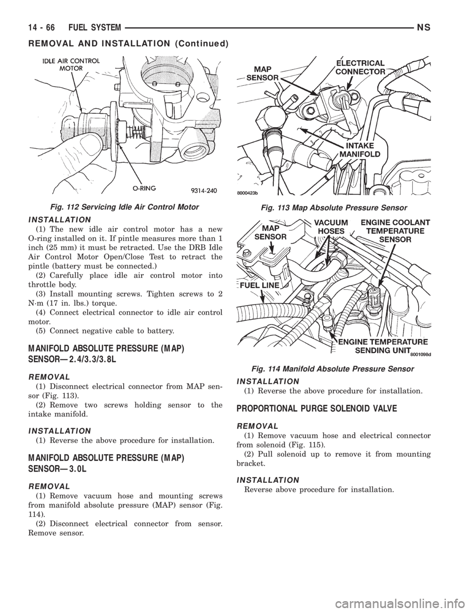
(1) Disconnect electrical connector from MAP sen-
sor (Fig. 113).
(2) Remove two screws holding sensor to the
intake manifold.
INSTALLATION
(1) Reverse the above procedure for installation.
MANIFOLD ABSOLUTE PRESSURE (MAP)
SENSORÐ3.0L
REMOVAL
(1) Remove vacuum hose and mounting screws
from manifold absolute pressure (MAP) sensor (Fig.
114).
(2) Disconnect electrical connector from sensor.
Remove sensor.
INSTALLATION
(1) Reverse the above procedure for installation.
PROPORTIONAL PURGE SOLENOID VALVE
REMOVAL
(1) Remove vacuum hose and electrical connector
from solenoid (Fig. 115).
(2) Pull solenoid up to remove it from mounting
bracket.
INSTALLATION
Reverse above procedure for installation.
Fig. 112 Servicing Idle Air Control MotorFig. 113 Map Absolute Pressure Sensor
Fig. 114 Manifold Absolute Pressure Sensor
14 - 66 FUEL SYSTEMNS
REMOVAL AND INSTALLATION (Continued)
Page 1363 of 1938
(4) When the sensor is removed, the exhaust man-
ifold threads must be cleaned with an 18 mm X 1.5 +
6E tap. If using original sensor, coat the threads with
Loctite 771-64 anti-seize compound or equivalent.
INSTALLATION
(1) Reverse removal procedure to install a new
sensor.
New sensors are packaged with compound on the
threads and no additional compound is required. The
sensor must be tightened to 27 N´m (20 ft. lbs.)
torque.
DOWNSTREAM OXYGEN SENSOR
REMOVAL
(1) Raise and support vehicle.
WARNING: THE EXHAUST MANIFOLD MAY BE
EXTREMELY HOT. USE CARE WHEN SERVICING
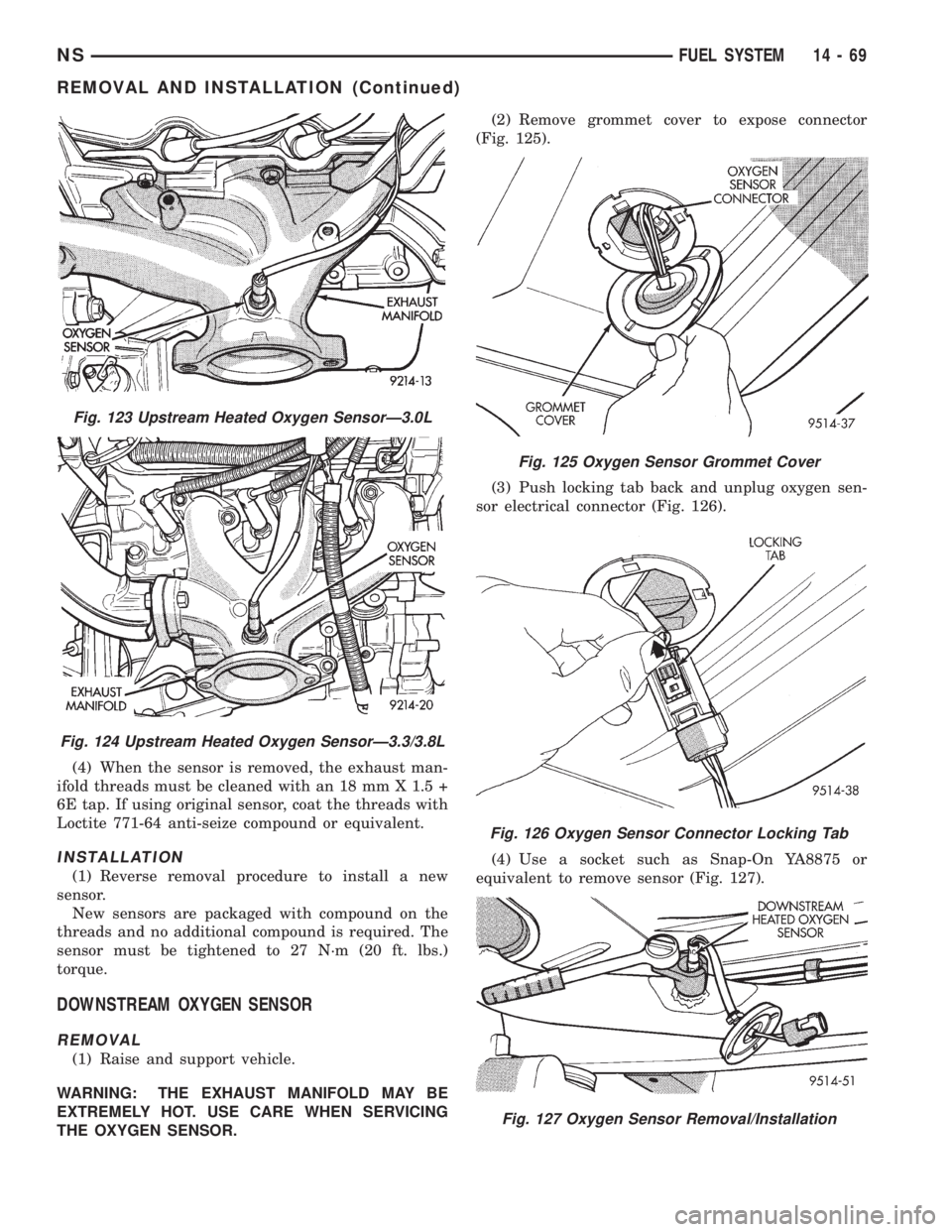
THE OXYGEN SENSOR.(2) Remove grommet cover to expose connector
(Fig. 125).
(3) Push locking tab back and unplug oxygen sen-
sor electrical connector (Fig. 126).
(4) Use a socket such as Snap-On YA8875 or
equivalent to remove sensor (Fig. 127).
Fig. 123 Upstream Heated Oxygen SensorÐ3.0L
Fig. 124 Upstream Heated Oxygen SensorÐ3.3/3.8L
Fig. 125 Oxygen Sensor Grommet Cover
Fig. 126 Oxygen Sensor Connector Locking Tab
Fig. 127 Oxygen Sensor Removal/Installation
NSFUEL SYSTEM 14 - 69
REMOVAL AND INSTALLATION (Continued)
Page 1364 of 1938
(5) When the sensor is removed, the exhaust man-
ifold threads must be cleaned with an 18 mm X 1.5 +
6E tap. If using original sensor, coat the threads with
Loctite 771-64 anti-seize compound or equivalent.
INSTALLATION
(1) Reverse removal procedure to install a new
sensor.
New sensors are packaged with compound on the
threads and no additional compound is required. The
sensor must be tightened to 27 N´m (20 ft. lbs.)
torque.
KNOCK SENSOR
For removal/installation procedures refer to Group
8D- Ignition System, Service Procedures.
AIR CLEANER ELEMENT
REMOVAL
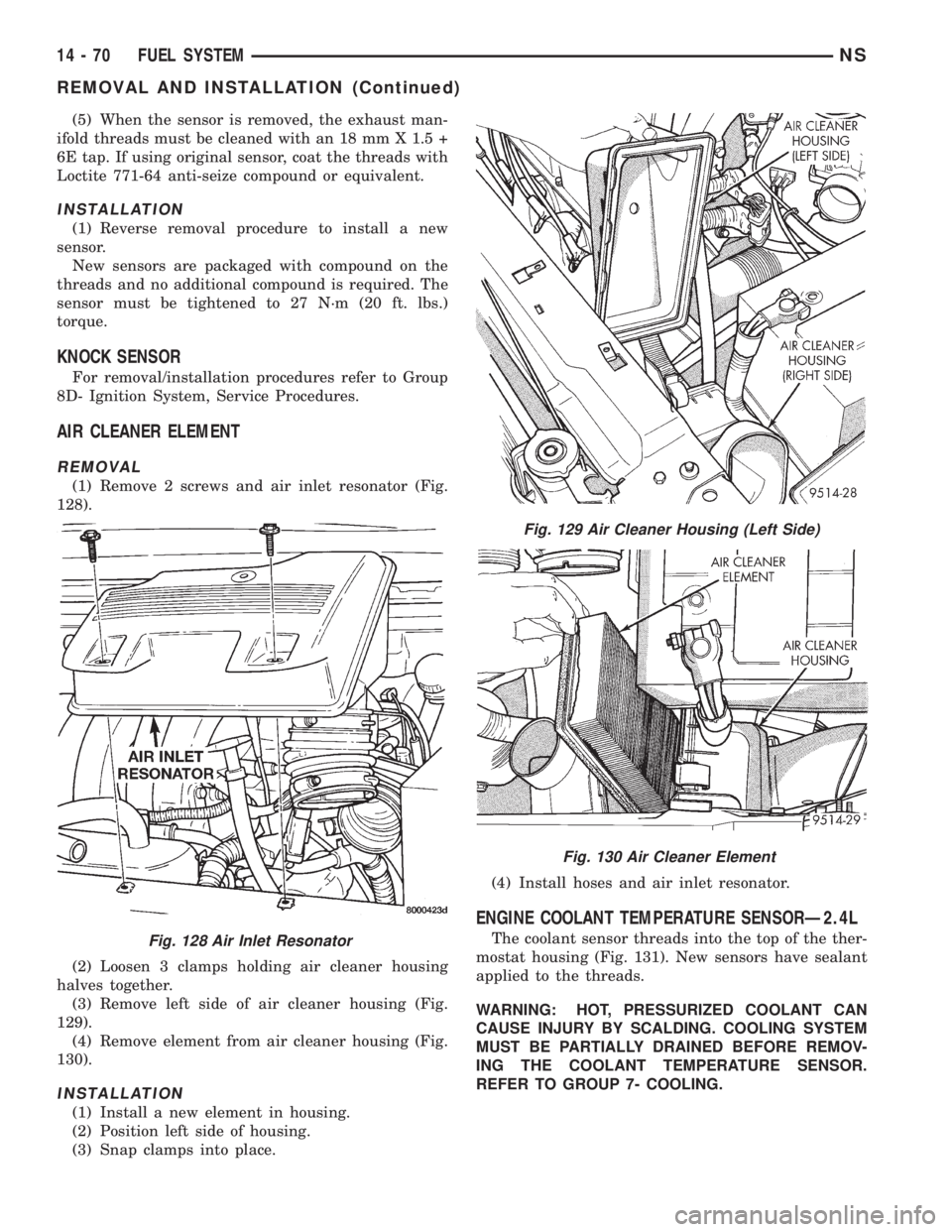
(1) Remove 2 screws and air inlet resonator (Fig.
128).
(2) Loosen 3 clamps holding air cleaner housing
halves together.
(3) Remove left side of air cleaner housing (Fig.
129).
(4) Remove element from air cleaner housing (Fig.
130).
INSTALLATION
(1) Install a new element in housing.
(2) Position left side of housing.
(3) Snap clamps into place.(4) Install hoses and air inlet resonator.
ENGINE COOLANT TEMPERATURE SENSORÐ2.4L
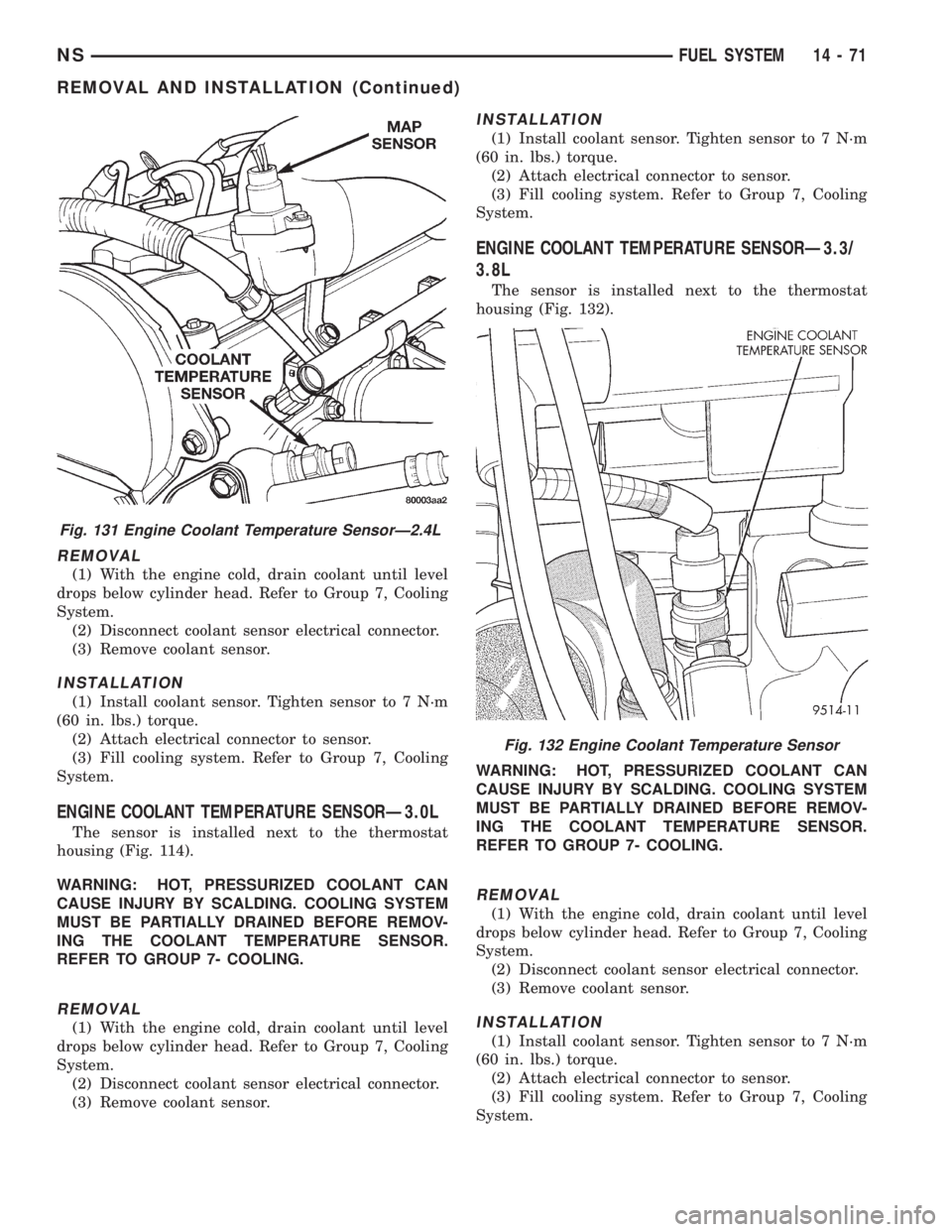
The coolant sensor threads into the top of the ther-
mostat housing (Fig. 131). New sensors have sealant
applied to the threads.
WARNING: HOT, PRESSURIZED COOLANT CAN
CAUSE INJURY BY SCALDING. COOLING SYSTEM
MUST BE PARTIALLY DRAINED BEFORE REMOV-
ING THE COOLANT TEMPERATURE SENSOR.
REFER TO GROUP 7- COOLING.Fig. 128 Air Inlet Resonator
Fig. 129 Air Cleaner Housing (Left Side)
Fig. 130 Air Cleaner Element
14 - 70 FUEL SYSTEMNS
REMOVAL AND INSTALLATION (Continued)
Page 1365 of 1938
REMOVAL
(1) With the engine cold, drain coolant until level
drops below cylinder head. Refer to Group 7, Cooling
System.
(2) Disconnect coolant sensor electrical connector.
(3) Remove coolant sensor.
INSTALLATION
(1) Install coolant sensor. Tighten sensor to 7 N´m
(60 in. lbs.) torque.
(2) Attach electrical connector to sensor.
(3) Fill cooling system. Refer to Group 7, Cooling
System.
ENGINE COOLANT TEMPERATURE SENSORÐ3.0L
The sensor is installed next to the thermostat
housing (Fig. 114).
WARNING: HOT, PRESSURIZED COOLANT CAN
CAUSE INJURY BY SCALDING. COOLING SYSTEM
MUST BE PARTIALLY DRAINED BEFORE REMOV-
ING THE COOLANT TEMPERATURE SENSOR.
REFER TO GROUP 7- COOLING.
REMOVAL
(1) With the engine cold, drain coolant until level
drops below cylinder head. Refer to Group 7, Cooling
System.
(2) Disconnect coolant sensor electrical connector.
(3) Remove coolant sensor.
INSTALLATION
(1) Install coolant sensor. Tighten sensor to 7 N´m
(60 in. lbs.) torque.
(2) Attach electrical connector to sensor.
(3) Fill cooling system. Refer to Group 7, Cooling
System.
ENGINE COOLANT TEMPERATURE SENSORÐ3.3/
3.8L
The sensor is installed next to the thermostat
housing (Fig. 132).
WARNING: HOT, PRESSURIZED COOLANT CAN
CAUSE INJURY BY SCALDING. COOLING SYSTEM
MUST BE PARTIALLY DRAINED BEFORE REMOV-
ING THE COOLANT TEMPERATURE SENSOR.
REFER TO GROUP 7- COOLING.
REMOVAL
(1) With the engine cold, drain coolant until level
drops below cylinder head. Refer to Group 7, Cooling
System.
(2) Disconnect coolant sensor electrical connector.
(3) Remove coolant sensor.
INSTALLATION
(1) Install coolant sensor. Tighten sensor to 7 N´m
(60 in. lbs.) torque.
(2) Attach electrical connector to sensor.
(3) Fill cooling system. Refer to Group 7, Cooling
System.
Fig. 131 Engine Coolant Temperature SensorÐ2.4L
Fig. 132 Engine Coolant Temperature Sensor
NSFUEL SYSTEM 14 - 71
REMOVAL AND INSTALLATION (Continued)
Page 1366 of 1938
INTAKE AIR TEMPERATURE SENSORÐ2.4L
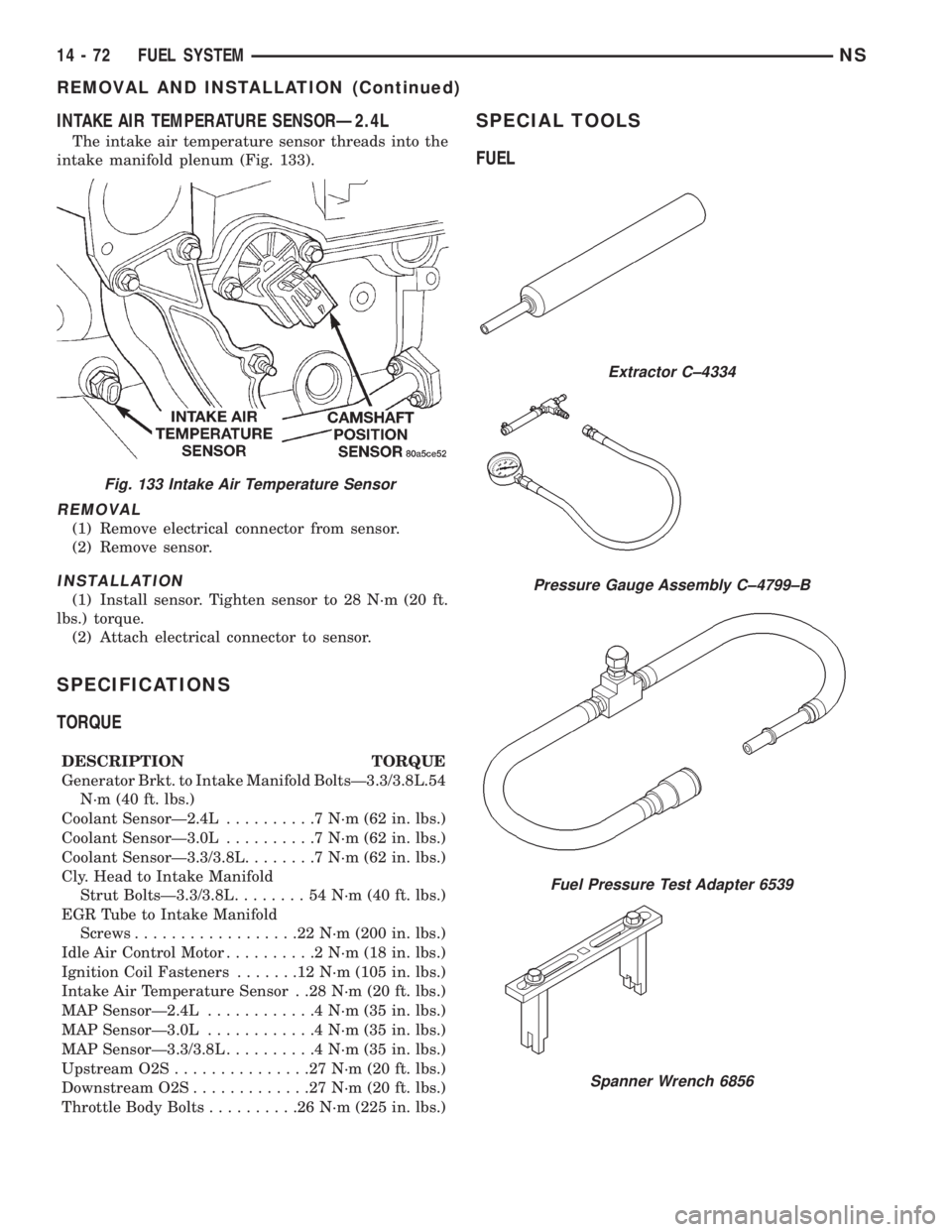
The intake air temperature sensor threads into the
intake manifold plenum (Fig. 133).
REMOVAL
(1) Remove electrical connector from sensor.
(2) Remove sensor.
INSTALLATION
(1) Install sensor. Tighten sensor to 28 N´m (20 ft.
lbs.) torque.
(2) Attach electrical connector to sensor.
SPECIFICATIONS
TORQUE
DESCRIPTION TORQUE
Generator Brkt. to Intake Manifold BoltsÐ3.3/3.8L.54
N´m (40 ft. lbs.)
Coolant SensorÐ2.4L..........7N´m(62in.lbs.)
Coolant SensorÐ3.0L..........7N´m(62in.lbs.)
Coolant SensorÐ3.3/3.8L........7N´m(62in.lbs.)
Cly. Head to Intake Manifold
Strut BoltsÐ3.3/3.8L........54N´m(40ft.lbs.)
EGR Tube to Intake Manifold
Screws..................22N´m(200 in. lbs.)
Idle Air Control Motor..........2N´m(18in.lbs.)
Ignition Coil Fasteners.......12N´m(105 in. lbs.)
Intake Air Temperature Sensor . .28 N´m (20 ft. lbs.)
MAP SensorÐ2.4L............4N´m(35in.lbs.)
MAP SensorÐ3.0L............4N´m(35in.lbs.)
MAP SensorÐ3.3/3.8L..........4N´m(35in.lbs.)
Upstream O2S...............27N´m(20ft.lbs.)
Downstream O2S.............27N´m(20ft.lbs.)
Throttle Body Bolts..........26N´m(225 in. lbs.)
SPECIAL TOOLS
FUEL
Fig. 133 Intake Air Temperature Sensor
Extractor C±4334
Pressure Gauge Assembly C±4799±B
Fuel Pressure Test Adapter 6539
Spanner Wrench 6856
14 - 72 FUEL SYSTEMNS
REMOVAL AND INSTALLATION (Continued)
Page 1375 of 1938
leaks are not present. The component should be
replaced immediately if there is any evidence of deg-
radation that could result in failure.
Never attempt to repair a plastic fuel line/tube or a
quick±connect fitting. Replace complete line/tube as
necessary.
Avoid contact of any fuel tubes/hoses with other
vehicle components that could cause abrasions or
scuffing. Be sure that the fuel lines/tubes are prop-
erly routed to prevent pinching and to avoid heat
sources.
The lines/tubes/hoses are of a special construction.
If it is necessary to replace these lines/tubes/hoses,
use only original equipment type.
The hose clamps used to secure the rubber hoses
are of a special rolled edge construction. This con-
struction is used to prevent the edge of the clamp
from cutting into the hose. Only these rolled edge
type clamps may be used in this system. All other
types of clamps may cut into the hoses and cause
fuel leaks.
Where a rubber hose is joined to a metal tube
(staked), do not attempt to repair. Replace entire
line/tube assembly.
Use new original equipment type hose clamps.
Tighten hose clamps to 2 N´m (20 in. lbs.) torque.
QUICK-CONNECT FITTINGSÐLOW PRESSURE
TYPE
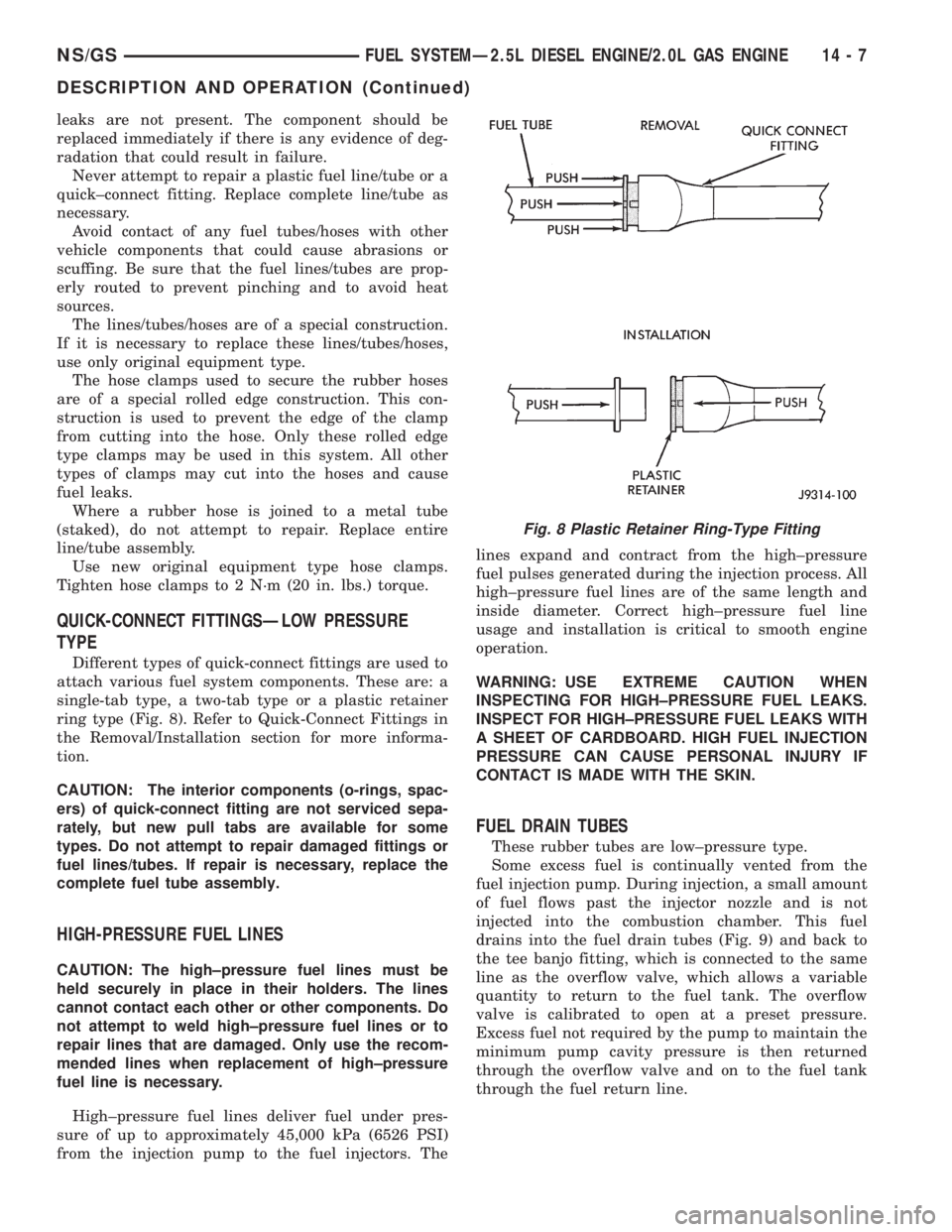
Different types of quick-connect fittings are used to
attach various fuel system components. These are: a
single-tab type, a two-tab type or a plastic retainer
ring type (Fig. 8). Refer to Quick-Connect Fittings in
the Removal/Installation section for more informa-
tion.
CAUTION: The interior components (o-rings, spac-
ers) of quick-connect fitting are not serviced sepa-
rately, but new pull tabs are available for some
types. Do not attempt to repair damaged fittings or
fuel lines/tubes. If repair is necessary, replace the
complete fuel tube assembly.
HIGH-PRESSURE FUEL LINES
CAUTION: The high±pressure fuel lines must be
held securely in place in their holders. The lines
cannot contact each other or other components. Do
not attempt to weld high±pressure fuel lines or to
repair lines that are damaged. Only use the recom-
mended lines when replacement of high±pressure
fuel line is necessary.
High±pressure fuel lines deliver fuel under pres-
sure of up to approximately 45,000 kPa (6526 PSI)
from the injection pump to the fuel injectors. Thelines expand and contract from the high±pressure
fuel pulses generated during the injection process. All
high±pressure fuel lines are of the same length and
inside diameter. Correct high±pressure fuel line
usage and installation is critical to smooth engine
operation.
WARNING: USE EXTREME CAUTION WHEN
INSPECTING FOR HIGH±PRESSURE FUEL LEAKS.
INSPECT FOR HIGH±PRESSURE FUEL LEAKS WITH
A SHEET OF CARDBOARD. HIGH FUEL INJECTION
PRESSURE CAN CAUSE PERSONAL INJURY IF
CONTACT IS MADE WITH THE SKIN.
FUEL DRAIN TUBES
These rubber tubes are low±pressure type.
Some excess fuel is continually vented from the
fuel injection pump. During injection, a small amount
of fuel flows past the injector nozzle and is not
injected into the combustion chamber. This fuel
drains into the fuel drain tubes (Fig. 9) and back to
the tee banjo fitting, which is connected to the same
line as the overflow valve, which allows a variable
quantity to return to the fuel tank. The overflow
valve is calibrated to open at a preset pressure.
Excess fuel not required by the pump to maintain the
minimum pump cavity pressure is then returned
through the overflow valve and on to the fuel tank
through the fuel return line.
Fig. 8 Plastic Retainer Ring-Type Fitting
NS/GSFUEL SYSTEMÐ2.5L DIESEL ENGINE/2.0L GAS ENGINE 14 - 7
DESCRIPTION AND OPERATION (Continued)
Page 1380 of 1938
FUEL HEATER RELAY TEST
The fuel heater relay is located in the Power Dis-
tribution Center (PDC). Refer to RelaysÐOperation/
Testing in Fuel Ingection System section of this
group for test procedures.
FUEL INJECTOR TEST
The fuel injection nozzels, located on the engine
cylinder head, spray fuel under high pressure into
the individual combustion chambers. Pressurized
fuel, delivered by the fuel injection pump, unseats a
spring-loaded needle valve inside the injector, and
the fuel is atomized as it escapes through the injector
opening into the engine's combustion chamber. If the
fuel injector does not operate properly, the engine
may misfire, or cause other driveability problems.
A leak in the injection pump±to±injector high±pres-
sure fuel line can cause many of the same symptoms
as a malfunctioning injector. Inspect for a leak in the
high±pressure lines before checking for a malfunc-
tioning fuel injector.
WARNING: THE INJECTION PUMP SUPPLIES HIGH-
±PRESSURE FUEL OF UP TO APPROXIMATELY
45,000 KPA (6526 PSI) TO EACH INDIVIDUAL INJEC-
TOR THROUGH THE HIGH±PRESSURE LINES. FUEL
UNDER THIS AMOUNT OF PRESSURE CAN PENE-
TRATE THE SKIN AND CAUSE PERSONAL INJURY.
WEAR SAFETY GOGGLES AND ADEQUATE PRO-
TECTIVE CLOTHING. AVOID CONTACT WITH FUEL
SPRAY WHEN BLEEDING HIGH±PRESSURE FUEL
LINES.
WARNING: DO NOT BLEED AIR FROM THE FUEL
SYSTEM OF A HOT ENGINE. DO NOT ALLOW FUEL
TO SPRAY ONTO THE EXHAUST MANIFOLD WHEN
BLEEDING AIR FROM THE FUEL SYSTEM.
To determine which fuel injector is malfunctioning,
run the engine and loosen the high±pressure fuel line
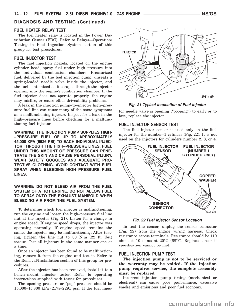
nut at the injector (Fig. 21). Listen for a change in
engine speed. If engine speed drops, the injector was
operating normally. If engine speed remains the
same, the injector may be malfunctioning. After test-
ing, tighten the line nut to 30 N´m (22 ft. lbs.)
torque. Test all injectors in the same manner one at
a time.
Once an injector has been found to be malfunction-
ing, remove it from the engine and test it. Refer to
the Removal/Installation section of this group for pro-
cedures.
After the injector has been removed, install it to a
bench±mount injector tester. Refer to operating
instructions supplied with tester for procedures.
The opening pressure or ªpopº pressure should be
15,000±15,800 kPa (2175±2291 psi). If the fuel injec-tor needle valve is opening (ªpoppingº) to early or to
late, replace the injector.
FUEL INJECTOR SENSOR TEST
The fuel injector sensor is used only on the fuel
injector for the number±1 cylinder (Fig. 22). It is not
used on the injectors for cylinders number 2, 3, or 4.
To test the sensor, unplug the sensor connector
(Fig. 22) from the engine wiring harness. Check
resistance across terminals. Resistance should be 110
ohms610 ohms at 20ÉC (68ÉF). Replace sensor if
specification cannot be met.
FUEL INJECTION PUMP TEST
The injection pump is not to be serviced or
the warranty may be voided. If the injection
pump requires service, the complete assembly
must be replaced.
Incorrect injection pump timing (mechanical or
electrical) can cause poor performance, excessive
smoke and emissions and poor fuel economy.
Fig. 21 Typical Inspection of Fuel Injector
Fig. 22 Fuel Injector Sensor Location
14 - 12 FUEL SYSTEMÐ2.5L DIESEL ENGINE/2.0L GAS ENGINENS/GS
DIAGNOSIS AND TESTING (Continued)
Page 1384 of 1938
REMOVAL AND INSTALLATION
ACCELERATOR PEDAL
CAUTION: Be careful not to damage or kink the
cable core wire (within the cable sheathing) while
servicing the accelerator pedal or throttle cable.
REMOVAL
(1) Disconnect electrical connector.
(2) Remove accelerator pedal mounting bracket
nuts. Remove accelerator pedal assembly.
INSTALLATION
(1) Place accelerator pedal assembly over studs
protruding from floor pan. Tighten mounting nuts to
5 N´m (46 in. lbs.) torque.
(2) Connect electrical connector.
(3) Before starting the engine, operate the acceler-
ator pedal to check for any binding.
AIR CLEANER ELEMENT
REMOVAL
(1) Remove hose clamp at Mass Air Flow Sensor.
(2) Remove hose from Mass Air Flow Sensor.(3) Loosen 2 clamps holding air cleaner housing
halves together.
(4) Remove left side of air cleaner housing.
(5) Remove element from air cleaner housing.
INSTALLATION
(1) Install a new element in housing.
(2) Position left side of housing.
(3) Snap clamps into place.
(4) Install hoses and clamps.
FUEL DRAIN TUBES
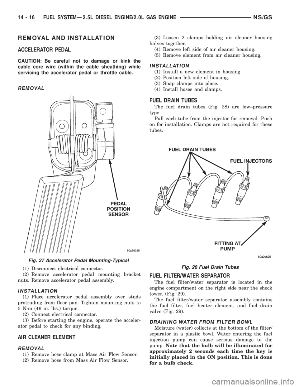
The fuel drain tubes (Fig. 28) are low±pressure
type.
Pull each tube from the injector for removal. Push
on for installation. Clamps are not required for these
tubes.
FUEL FILTER/WATER SEPARATOR
The fuel filter/water separator is located in the
engine compartment on the right side near the shock
tower. (Fig. 29).
The fuel filter/water separator assembly contains
the fuel filter, fuel heater element, and fuel drain
valve (Fig. 29).
DRAINING WATER FROM FILTER BOWL
Moisture (water) collects at the bottom of the filter/
separator in a plastic bowl. Water entering the fuel
injection pump can cause serious damage to the
pump.Note that the bulb will be illuminated for
approximately 2 seconds each time the key is
initially placed in the ON position. This is done
for a bulb check.
Fig. 27 Accelerator Pedal Mounting-Typical
Fig. 28 Fuel Drain Tubes
14 - 16 FUEL SYSTEMÐ2.5L DIESEL ENGINE/2.0L GAS ENGINENS/GS