torque CHRYSLER VOYAGER 1996 Service Manual
[x] Cancel search | Manufacturer: CHRYSLER, Model Year: 1996, Model line: VOYAGER, Model: CHRYSLER VOYAGER 1996Pages: 1938, PDF Size: 55.84 MB
Page 1270 of 1938
(2) Tighten intake manifold fasteners in the fol-
lowing sequence (Fig. 16). Torque to 23 N´m (200 in.
lbs.). Repeat this procedure until all bolts are at
specified torque.
(3) Install intake manifold center support bracket
bolts (Y bracket):
²Fastener to block 54 N´m (40 ft. lbs.)
²Fastener to intake 28 N´m (250 in. lbs.)
(4) Install fuel hose quick connector fitting to
chassis tubes.Refer to Fuel Hoses, Clamps and
Quick Connect Fittings in Group 14, Fuel Deliv-
ery.Push the fitting onto the chassis tube until it
clicks into place. Pull on the fitting to ensure com-
plete insertion.
(5) Reverse removal procedures 2 through 12 for
installation.
CAUTION: When using the ASD Fuel System Test,
the ASD relay and fuel pump relay remain energized
for 7 minutes or until the test is stopped, or until
the ignition switch is turned to the Off position.
(6) With the ignition key in ON position, access
the DRB scan tool ASD Fuel System Test to pressur-
ize the fuel system. Check for leaks.
EXHAUST MANIFOLDÐ2.4L ENGINE
REMOVAL
(1) Raise vehicle and disconnect exhaust pipe from
the exhaust manifold at the flex-joint.
(2) Disconnect Oxygen Sensor lead wire at the rear
exhaust manifold (Fig. 17).
(3) Remove the bolts attaching the manifold to the
cylinder head. Remove manifold (Fig. 17).
(4) Inspect and clean manifold. Refer to Cleaning
and Inspection outlined in this section for proce-
dures.
INSTALLATION
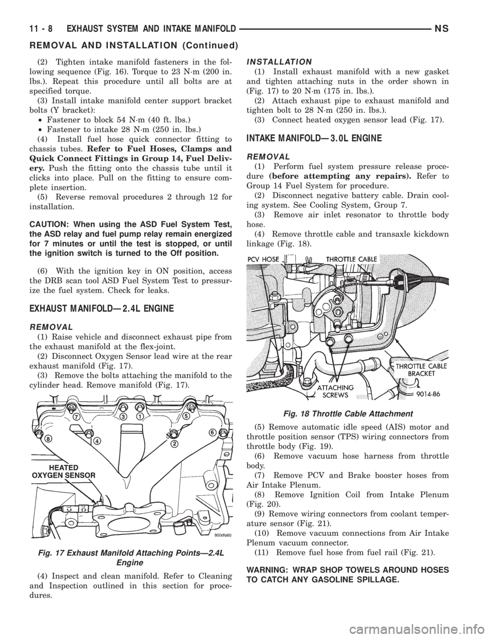
(1) Install exhaust manifold with a new gasket
and tighten attaching nuts in the order shown in
(Fig. 17) to 20 N´m (175 in. lbs.).
(2) Attach exhaust pipe to exhaust manifold and
tighten bolt to 28 N´m (250 in. lbs.).
(3) Connect heated oxygen sensor lead (Fig. 17).
INTAKE MANIFOLDÐ3.0L ENGINE
REMOVAL
(1) Perform fuel system pressure release proce-
dure(before attempting any repairs).Refer to
Group 14 Fuel System for procedure.
(2) Disconnect negative battery cable. Drain cool-
ing system. See Cooling System, Group 7.
(3) Remove air inlet resonator to throttle body
hose.
(4) Remove throttle cable and transaxle kickdown
linkage (Fig. 18).
(5) Remove automatic idle speed (AIS) motor and
throttle position sensor (TPS) wiring connectors from
throttle body (Fig. 19).
(6) Remove vacuum hose harness from throttle
body.
(7) Remove PCV and Brake booster hoses from
Air Intake Plenum.
(8) Remove Ignition Coil from Intake Plenum
(Fig. 20).
(9) Remove wiring connectors from coolant temper-
ature sensor (Fig. 21).
(10) Remove vacuum connections from Air Intake
Plenum vacuum connector.
(11) Remove fuel hose from fuel rail (Fig. 21).
WARNING: WRAP SHOP TOWELS AROUND HOSES
TO CATCH ANY GASOLINE SPILLAGE.
Fig. 17 Exhaust Manifold Attaching PointsÐ2.4L
Engine
Fig. 18 Throttle Cable Attachment
11 - 8 EXHAUST SYSTEM AND INTAKE MANIFOLDNS
REMOVAL AND INSTALLATION (Continued)
Page 1272 of 1938
(16) Remove fuel rail attaching bolts and lift fuel
rail assembly from intake manifold.
(17) Separate radiator hose from thermostat hous-
ing and heater hose from heater pipe.
(18) Remove nut and washer assemblies and
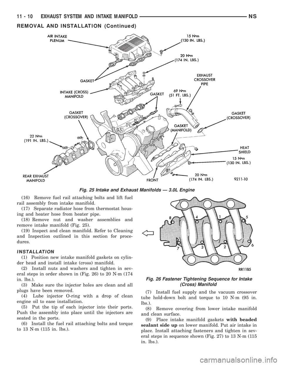
remove intake manifold (Fig. 25).
(19) Inspect and clean manifold. Refer to Cleaning
and Inspection outlined in this section for proce-
dures.
INSTALLATION
(1) Position new intake manifold gaskets on cylin-
der head and install intake (cross) manifold.
(2) Install nuts and washers and tighten in sev-
eral steps in order shown in (Fig. 26) to 20 N´m (174
in. lbs.).
(3) Make sure the injector holes are clean and all
plugs have been removed.
(4) Lube injector O-ring with a drop of clean
engine oil to ease installation.
(5) Put the tip of each injector into their ports.
Push the assembly into place until the injectors are
seated in the ports.
(6) Install the fuel rail attaching bolts and torque
to 13 N´m (115 in. lbs.).(7) Install fuel supply and the vacuum crossover
tube hold-down bolt and torque to 10 N´m (95 in.
lbs.).
(8) Remove covering from lower intake manifold
and clean surface.
(9) Place intake manifold gasketswith beaded
sealant side upon lower manifold. Put air intake in
place. Install attaching fasteners and tighten in sev-
eral steps in sequence shown (Fig. 27) to 13 N´m (115
in. lbs.).
Fig. 25 Intake and Exhaust Manifolds Ð 3.0L Engine
Fig. 26 Fastener Tightening Sequence for Intake
(Cross) Manifold
11 - 10 EXHAUST SYSTEM AND INTAKE MANIFOLDNS
REMOVAL AND INSTALLATION (Continued)
Page 1273 of 1938
(10) Connect fuel line to fuel rail (Fig. 21). Torque
hose clamps to 1 N´m (10 in. lbs.).
(11) Connect vacuum harness to air intake ple-
num.
(12) Connect and coolant temperature sensor elec-
trical connector to sensor (Fig. 21).
(13) Connect PCV and brake booster supply hose
to intake plenum.
(14) Connect automatic idle speed (AIS) motor
and throttle position sensor (TPS) electrical connec-
tors (Fig. 19).
(15) Connect vacuum vapor harness to throttle
body (Fig. 19).
(16) Install throttle cable and transaxle kickdown
linkage (Fig. 18).
(17) Install air inlet resonator hose assembly to
throttle body.
(18) Install radiator to thermostat housing hose
and heater hose to heater pipe nipple.
(19) Fill cooling system. Refer to Filling the Cool-
ing System outlined in Group 7 Cooling System for
procedure.
(20) Connect negative battery cable.
(21) With the DRB Scan Tool use ASD Fuel Sys-
tem Test to pressurize system to check for leaks.
CAUTION: When using the ASD Fuel System Test,
The Auto Shutdown (ASD) Relay will remain ener-
gized for 7 minutes or until the ignition switch is
turned to the OFF position, or Stop All Test is
selected.
EXHAUST MANIFOLDÐ3.0L ENGINE
REMOVAL
(1) Raise vehicle and disconnect exhaust pipe
from rear (cowl side) exhaust manifold at the flex-
joint.(2) Disconnect Oxygen Sensor lead wire at the
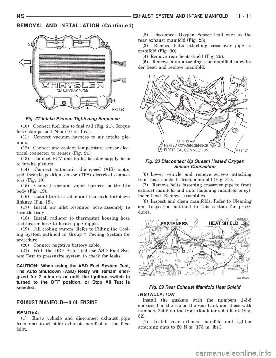
rear exhaust manifold (Fig. 28).
(3) Remove bolts attaching cross-over pipe to
manifold (Fig. 30).
(4) Remove rear heat shield (Fig. 29).
(5) Remove nuts attaching rear manifold to cylin-
der head and remove manifold.
(6) Lower vehicle and remove screws attaching
front heat shield to front manifold (Fig. 31).
(7) Remove bolts fastening crossover pipe to front
exhaust manifold and nuts fastening manifold to cyl-
inder head. Remove assemblies.
(8) Inspect and clean manifolds. Refer to Cleaning
and Inspection outlined in this section for proce-
dures.
INSTALLATION
Install the gaskets with the numbers 1-3-5
embossed on the top on the rear bank and those with
numbers 2-4-6 on the front (Radiator side) bank (Fig.
32).
(1) Install rear exhaust manifold and tighten
attaching nuts to 20 N´m (175 in. lbs.).
Fig. 27 Intake Plenum Tightening Sequence
Fig. 28 Disconnect Up Stream Heated Oxygen
Sensor Connection
Fig. 29 Rear Exhaust Manifold Heat Shield
NSEXHAUST SYSTEM AND INTAKE MANIFOLD 11 - 11
REMOVAL AND INSTALLATION (Continued)
Page 1276 of 1938
(25) Remove intake manifold bolts. Remove intake
manifold.
(26) Inspect and clean manifold. Refer to Cleaning
and Inspection outlined in this section for proce-
dures.
WARNING: INTAKE MANIFOLD GASKET IS MADE
OF VERY THIN METAL AND MAY CAUSE PER-
SONAL INJURY, HANDLE WITH CARE.
(27) Remove intake manifold seal retainers screws
(Fig. 43). Remove intake manifold gasket.
INSTALLATION
(1) Clean all surfaces of cylinder block and cylin-
der heads.
(2) Place a drop (approximately 1/4 in. diameter)
of MopartSilicone Rubber Adhesive Sealant or
equivalent, onto each of thefourmanifold to cylinder
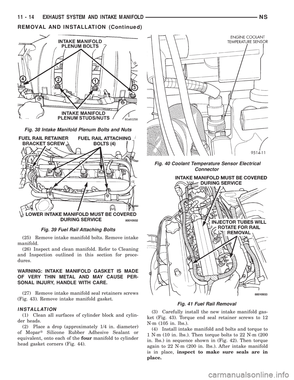
head gasket corners (Fig. 44).(3) Carefully install the new intake manifold gas-
ket (Fig. 43). Torque end seal retainer screws to 12
N´m (105 in. lbs.).
(4) Install intake manifold and bolts and torque to
1 N´m (10 in. lbs.). Then torque bolts to 22 N´m (200
in. lbs.) in sequence shown in (Fig. 42). Then torque
again to 22 N´m (200 in. lbs.). After intake manifold
is in place,inspect to make sure seals are in
place.
Fig. 38 Intake Manifold Plenum Bolts and Nuts
Fig. 39 Fuel Rail Attaching Bolts
Fig. 40 Coolant Temperature Sensor Electrical
Connector
Fig. 41 Fuel Rail Removal
11 - 14 EXHAUST SYSTEM AND INTAKE MANIFOLDNS
REMOVAL AND INSTALLATION (Continued)
Page 1277 of 1938
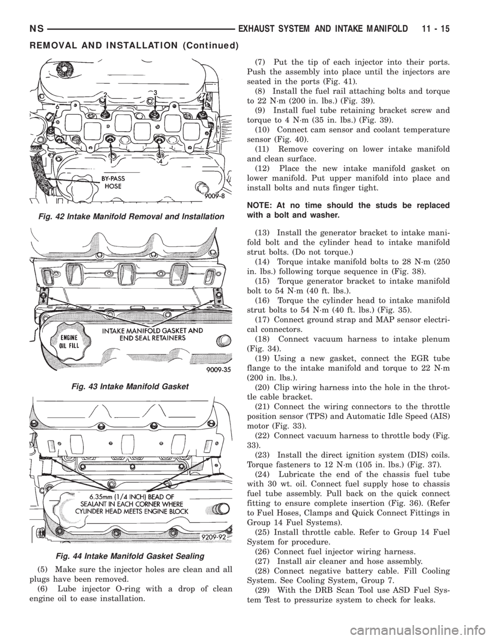
(5) Make sure the injector holes are clean and all
plugs have been removed.
(6) Lube injector O-ring with a drop of clean
engine oil to ease installation.(7) Put the tip of each injector into their ports.
Push the assembly into place until the injectors are
seated in the ports (Fig. 41).
(8) Install the fuel rail attaching bolts and torque
to 22 N´m (200 in. lbs.) (Fig. 39).
(9) Install fuel tube retaining bracket screw and
torque to 4 N´m (35 in. lbs.) (Fig. 39).
(10) Connect cam sensor and coolant temperature
sensor (Fig. 40).
(11) Remove covering on lower intake manifold
and clean surface.
(12) Place the new intake manifold gasket on
lower manifold. Put upper manifold into place and
install bolts and nuts finger tight.
NOTE: At no time should the studs be replaced
with a bolt and washer.
(13) Install the generator bracket to intake mani-
fold bolt and the cylinder head to intake manifold
strut bolts. (Do not torque.)
(14) Torque intake manifold bolts to 28 N´m (250
in. lbs.) following torque sequence in (Fig. 38).
(15) Torque generator bracket to intake manifold
bolt to 54 N´m (40 ft. lbs.).
(16) Torque the cylinder head to intake manifold
strut bolts to 54 N´m (40 ft. lbs.) (Fig. 35).
(17) Connect ground strap and MAP sensor electri-
cal connectors.
(18) Connect vacuum harness to intake plenum
(Fig. 34).
(19) Using a new gasket, connect the EGR tube
flange to the intake manifold and torque to 22 N´m
(200 in. lbs.).
(20) Clip wiring harness into the hole in the throt-
tle cable bracket.
(21) Connect the wiring connectors to the throttle
position sensor (TPS) and Automatic Idle Speed (AIS)
motor (Fig. 33).
(22) Connect vacuum harness to throttle body (Fig.
33).
(23) Install the direct ignition system (DIS) coils.
Torque fasteners to 12 N´m (105 in. lbs.) (Fig. 37).
(24) Lubricate the end of the chassis fuel tube
with 30 wt. oil. Connect fuel supply hose to chassis
fuel tube assembly. Pull back on the quick connect
fitting to ensure complete insertion (Fig. 36). (Refer
to Fuel Hoses, Clamps and Quick Connect Fittings in
Group 14 Fuel Systems).
(25) Install throttle cable. Refer to Group 14 Fuel
System for procedure.
(26) Connect fuel injector wiring harness.
(27) Install air cleaner and hose assembly.
(28) Connect negative battery cable. Fill Cooling
System. See Cooling System, Group 7.
(29) With the DRB Scan Tool use ASD Fuel Sys-
tem Test to pressurize system to check for leaks.
Fig. 42 Intake Manifold Removal and Installation
Fig. 43 Intake Manifold Gasket
Fig. 44 Intake Manifold Gasket Sealing
NSEXHAUST SYSTEM AND INTAKE MANIFOLD 11 - 15
REMOVAL AND INSTALLATION (Continued)
Page 1280 of 1938
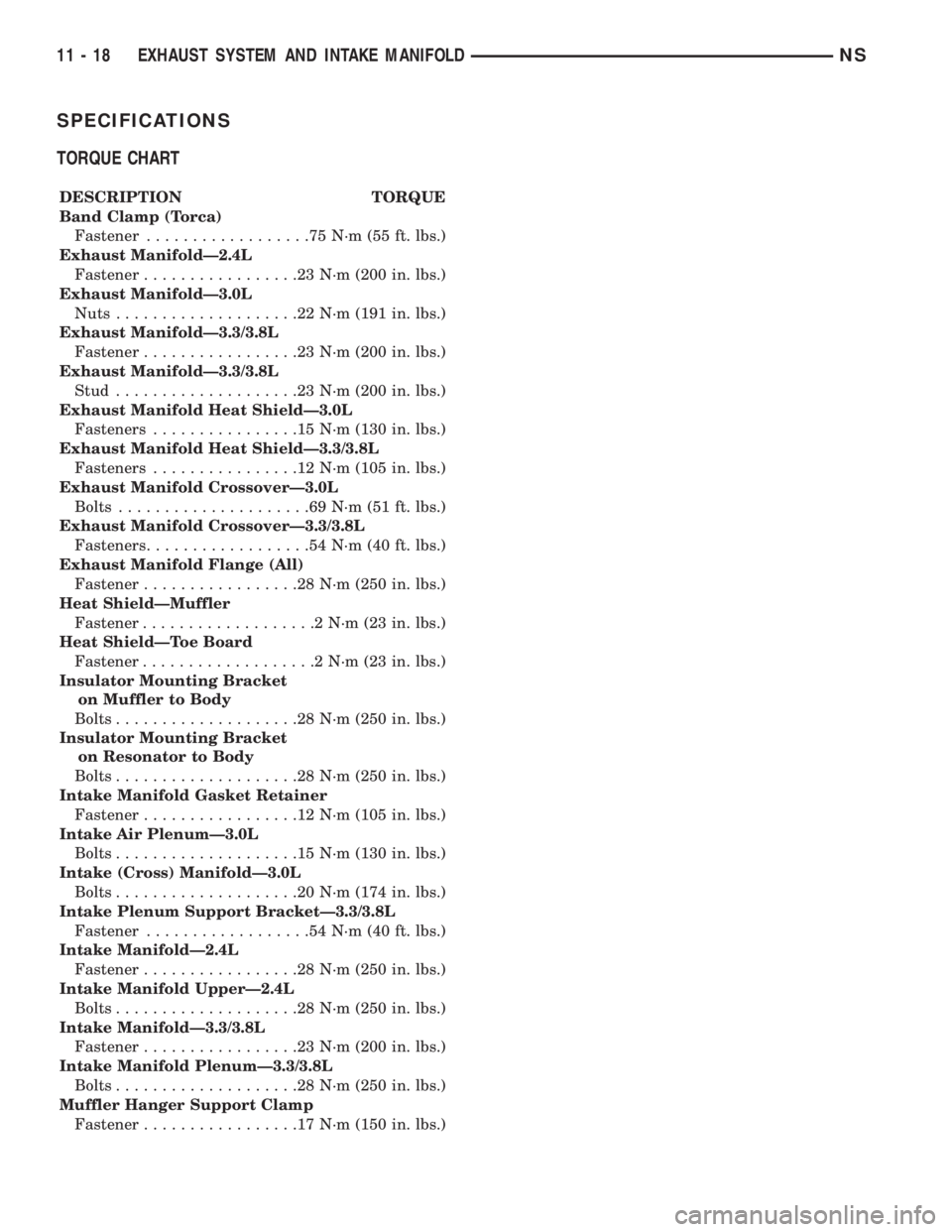
SPECIFICATIONS
TORQUE CHART
DESCRIPTION TORQUE
Band Clamp (Torca)
Fastener..................75N´m(55ft.lbs.)
Exhaust ManifoldÐ2.4L
Fastener.................23N´m(200 in. lbs.)
Exhaust ManifoldÐ3.0L
Nuts....................22N´m(191 in. lbs.)
Exhaust ManifoldÐ3.3/3.8L
Fastener.................23N´m(200 in. lbs.)
Exhaust ManifoldÐ3.3/3.8L
Stud....................23N´m(200 in. lbs.)
Exhaust Manifold Heat ShieldÐ3.0L
Fasteners................15N´m(130 in. lbs.)
Exhaust Manifold Heat ShieldÐ3.3/3.8L
Fasteners................12N´m(105 in. lbs.)
Exhaust Manifold CrossoverÐ3.0L
Bolts.....................69N´m(51ft.lbs.)
Exhaust Manifold CrossoverÐ3.3/3.8L
Fasteners..................54N´m(40ft.lbs.)
Exhaust Manifold Flange (All)
Fastener.................28N´m(250 in. lbs.)
Heat ShieldÐMuffler
Fastener...................2N´m(23in.lbs.)
Heat ShieldÐToe Board
Fastener...................2N´m(23in.lbs.)
Insulator Mounting Bracket
on Muffler to Body
Bolts....................28N´m(250 in. lbs.)
Insulator Mounting Bracket
on Resonator to Body
Bolts....................28N´m(250 in. lbs.)
Intake Manifold Gasket Retainer
Fastener.................12N´m(105 in. lbs.)
Intake Air PlenumÐ3.0L
Bolts....................15N´m(130 in. lbs.)
Intake (Cross) ManifoldÐ3.0L
Bolts....................20N´m(174 in. lbs.)
Intake Plenum Support BracketÐ3.3/3.8L
Fastener..................54N´m(40ft.lbs.)
Intake ManifoldÐ2.4L
Fastener.................28N´m(250 in. lbs.)
Intake Manifold UpperÐ2.4L
Bolts....................28N´m(250 in. lbs.)
Intake ManifoldÐ3.3/3.8L
Fastener.................23N´m(200 in. lbs.)
Intake Manifold PlenumÐ3.3/3.8L
Bolts....................28N´m(250 in. lbs.)
Muffler Hanger Support Clamp
Fastener.................17N´m(150 in. lbs.)
11 - 18 EXHAUST SYSTEM AND INTAKE MANIFOLDNS
Page 1282 of 1938
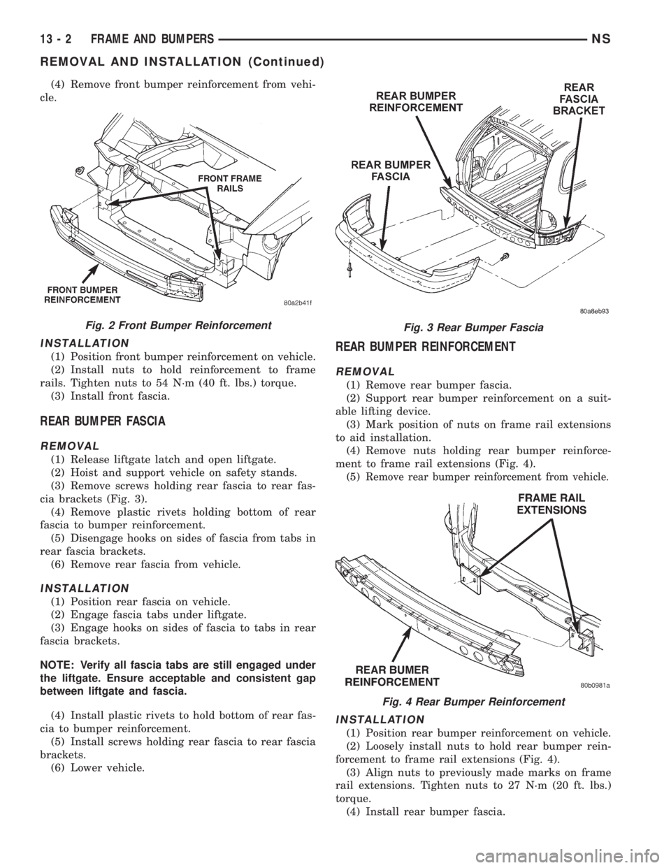
(4) Remove front bumper reinforcement from vehi-
cle.
INSTALLATION
(1) Position front bumper reinforcement on vehicle.
(2) Install nuts to hold reinforcement to frame
rails. Tighten nuts to 54 N´m (40 ft. lbs.) torque.
(3) Install front fascia.
REAR BUMPER FASCIA
REMOVAL
(1) Release liftgate latch and open liftgate.
(2) Hoist and support vehicle on safety stands.
(3) Remove screws holding rear fascia to rear fas-
cia brackets (Fig. 3).
(4) Remove plastic rivets holding bottom of rear
fascia to bumper reinforcement.
(5) Disengage hooks on sides of fascia from tabs in
rear fascia brackets.
(6) Remove rear fascia from vehicle.
INSTALLATION
(1) Position rear fascia on vehicle.
(2) Engage fascia tabs under liftgate.
(3) Engage hooks on sides of fascia to tabs in rear
fascia brackets.
NOTE: Verify all fascia tabs are still engaged under
the liftgate. Ensure acceptable and consistent gap
between liftgate and fascia.
(4) Install plastic rivets to hold bottom of rear fas-
cia to bumper reinforcement.
(5) Install screws holding rear fascia to rear fascia
brackets.
(6) Lower vehicle.
REAR BUMPER REINFORCEMENT
REMOVAL
(1) Remove rear bumper fascia.
(2) Support rear bumper reinforcement on a suit-
able lifting device.
(3) Mark position of nuts on frame rail extensions
to aid installation.
(4) Remove nuts holding rear bumper reinforce-
ment to frame rail extensions (Fig. 4).
(5)
Remove rear bumper reinforcement from vehicle.
INSTALLATION
(1) Position rear bumper reinforcement on vehicle.
(2) Loosely install nuts to hold rear bumper rein-
forcement to frame rail extensions (Fig. 4).
(3) Align nuts to previously made marks on frame
rail extensions. Tighten nuts to 27 N´m (20 ft. lbs.)
torque.
(4) Install rear bumper fascia.
Fig. 2 Front Bumper ReinforcementFig. 3 Rear Bumper Fascia
Fig. 4 Rear Bumper Reinforcement
13 - 2 FRAME AND BUMPERSNS
REMOVAL AND INSTALLATION (Continued)
Page 1285 of 1938
(7) Connect lower ball joints to lower control arms.
Refer to Group 2, Suspension.
(8) Connect stabilizer bar links to ends of stabi-
lizer bar. Refer to Group 2, Suspension.
(9) Install bolts to hold anti-lock brake sensor
leads to crossmember.
(10) Install high pressure hose to pump.
(11) Connect return hose to metal tube.
(12) Tighten hose clamp at the crossmember cou-
pling.
(13) Remove pinch-off pliers.
(14) Position steering so front wheels are straight
ahead.
(15) Install steering column coupling to telescoping
steering gear shaft.
(16) Install clinch bolt to hold steering column cou-
pling to steering gear shaft.
(17) Install knee blocker reinforcement. Refer to
Group 8E, Instrument Panel and Systems.
(18) Install steering column lower cover from
instrument panel. Refer to Group 8E, Instrument
Panel and Systems.
(19) Connect battery negative cable.
FRONT CROSSMEMBER MOUNT BUSHINGS
REMOVAL
(1) Using paint or grease pencil, mark outline of
crossmember on frame rails.
(2) Loosen bolts holding crossmember to frame
rails.
(3) Remove bolt on bushing that requires replace-
ment.
(4) Allow crossmember to drop down enough to
gain clearance for bushing removal.
(5) Remove bushing from vehicle.
INSTALLATION
(1) Apply rubber lube or soap to replacement bush-
ing.(2) Insert lower half of bushing into square hole in
crossmember.
(3) Place upper half of bushing on top of cross-
member aligned to receive square tube protruding
upward from lower bushing half.
(4) Squeeze bushing halves together to ensure they
are properly mated.
(5) Lift crossmember upward to close gap between
the bushing and frame.
(6) Verify that lower bushing is fully seated into
crossmember and upper bushing.
(7) Install bolt to hold bushing and crossmember
to frame rail hand tight.
(8) Align crossmember to reference marks on
frame rails.
(9) Tighten crossmember to frame rails attaching
bolts to 163 N´m (120 ft. lbs.) torque.
SPECIFICATIONS
FRAME AND BODY OPENING DIMENSIONS
Frame dimensions are listed in metric scale. All
dimensions are from center to center of Principal
Locating Point (PLP), or from center to center of PLP
and fastener location.
VEHICLE PREPARATION
Position the vehicle on a frame alignment rack,
refer to instructions provided with equipment being
used. Adjust the vehicle PLP heights to the specified
dimension above the work surface (datum line). Ver-
tical dimensions can be taken from the datum line to
the locations indicated were applicable. Refer to (Fig.
5), (Fig. 6), (Fig. 7), (Fig. 8), (Fig. 9), (Fig. 10) and
(Fig. 11) for proper dimensions.
NSFRAME AND BUMPERS 13 - 5
REMOVAL AND INSTALLATION (Continued)
Page 1298 of 1938
FUEL DELIVERY SYSTEM
INDEX
page page
DESCRIPTION AND OPERATION
FUEL DELIVERY SYSTEM.................. 4
FUEL INJECTORS........................ 5
FUEL LEVEL SENSOR..................... 5
FUEL PRESSURE REGULATOR.............. 5
FUEL PUMP MODULE..................... 4
FUEL TANK............................. 5
PRESSURE-VACUUM FILLER CAP........... 6
QUICK-CONNECT FITTINGS................ 6
DIAGNOSIS AND TESTING
FUEL INJECTORS........................ 9
FUEL LEVEL SENSOR..................... 9
FUEL PUMP PRESSURE TEST 2.4/3.3/3.8L..... 6
SERVICE PROCEDURES
FUEL SYSTEM PRESSURE RELEASE
PROCEDUREÐ2.4/3.3/3.8L............... 11
FUEL SYSTEM PRESSURE RELEASE
PROCEDUREÐ3.0L ENGINE............. 11
HOSES AND CLAMPS.................... 12QUICK-CONNECT FITTINGS............... 12
REMOVAL AND INSTALLATION
ACCELERATOR PEDAL................... 26
FUEL FILTER........................... 12
FUEL INJECTOR RAILÐ2.4L............... 18
FUEL INJECTOR RAILÐ3.0L............... 19
FUEL INJECTOR RAILÐ3.3/3.8L............ 21
FUEL INJECTORSÐ3.0L.................. 25
FUEL INJECTORÐ2.4L................... 24
FUEL INJECTORÐ3.3/3.8L................. 26
FUEL LEVEL SENSOR.................... 15
FUEL PRESSURE REGULATOR............. 14
FUEL PUMP INLET STRAINER............. 15
FUEL PUMP MODULE.................... 13
FUEL TANK............................ 17
THROTTLE CABLE...................... 27
SPECIFICATIONS
FUEL TANK CAPACITY................... 28
TORQUE.............................. 28
DESCRIPTION AND OPERATION
FUEL DELIVERY SYSTEM
The front wheel drive van uses a plastic fuel tank
located on the left side of the vehicle.
The Fuel Delivery System consists of: the electric
fuel pump module, fuel filter, tubes/lines/hoses, fuel
rail, and fuel injectors.
The in-tank fuel pump module contains the fuel
pump and pressure regulator. The pump is serviced
as part of the fuel pump module. Refer to Fuel Pump
Module.
The fuel filter is a replaceable in-line filter. The fil-
ter attaches to a bracket mounted on top of the fuel
tank. Refer to the Maintenance Schedules in the
Introduction section of this manual for recommended
fuel filter replacement intervals.
A returnless fuel system is used on all vehicles.
Fuel is returned through the fuel pump module and
back to the fuel tank. A separate fuel return line
from the tank to the engine is no longer used.
FUEL PUMP MODULE
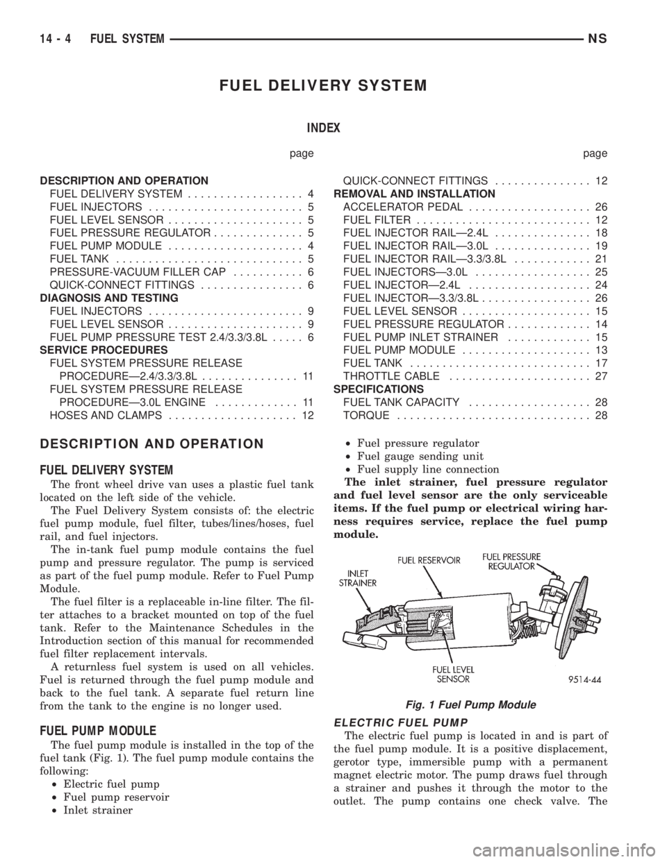
The fuel pump module is installed in the top of the
fuel tank (Fig. 1). The fuel pump module contains the
following:
²Electric fuel pump
²Fuel pump reservoir
²Inlet strainer²Fuel pressure regulator
²Fuel gauge sending unit
²Fuel supply line connection
The inlet strainer, fuel pressure regulator
and fuel level sensor are the only serviceable
items. If the fuel pump or electrical wiring har-
ness requires service, replace the fuel pump
module.
ELECTRIC FUEL PUMP
The electric fuel pump is located in and is part of
the fuel pump module. It is a positive displacement,
gerotor type, immersible pump with a permanent
magnet electric motor. The pump draws fuel through
a strainer and pushes it through the motor to the
outlet. The pump contains one check valve. The
Fig. 1 Fuel Pump Module
14 - 4 FUEL SYSTEMNS
Page 1306 of 1938
(9) Momentarily touch the other end of this
jumper wire to the negative terminal of the battery
for no more than 4 seconds.
(10) Place a rag or towel below the fuel line at the
quick connect to the rail.
(11) Disconnect the quick connect fitting to the
rail. Refer to Quick-Connect Fittings in this section.
(12) Return the fuel pump relay to the PDC.
(13) One or more Diagnostic Trouble Codes (DTC's)
may have been stored in the PCM memory due to the
fuel pump relay removal. The DRB scan tool must be
used to erase a DTC. Refer to group 25, On-Board
Diagnostics.
HOSES AND CLAMPS
Inspect all hose connections (clamps and quick con-
nect fittings) for completeness and leaks. Replace
cracked, scuffed, or swelled hoses. Replace hoses that
rub against other vehicle components or show sign of
wear.
Fuel injected vehicles use specially constructed
hoses. When replacing hoses, only use hoses marked
EFM/EFI.
When installing hoses, ensure that they are routed
away from contact with other vehicle components
that could rub against them and cause failure. Avoid
contact with clamps or other components that cause
abrasions or scuffing. Ensure that rubber hoses are
properly routed and avoid heat sources.
The hose clamps have rolled edges to prevent the
clamp from cutting into the hose. Only use clamps
that are original equipment or equivalent. Other
types of clamps may cut into the hoses and cause
high pressure fuel leaks. Tighten hose clamps to 1
N´m (10 in. lbs.) torque.
QUICK-CONNECT FITTINGS
REMOVAL
When disconnecting a quick-connect fitting, the
retainer will remain on the fuel tube nipple.
WARNING: RELEASE FUEL SYSTEM PRESSURE
BEFORE DISCONNECTING A QUICK-CONNECT FIT-
TINGS. REFER TO THE FUEL PRESSURE RELEASE
PROCEDURE.
(1) Disconnect negative cable from battery.
(2) Perform Fuel Pressure Release Procedure.
Refer to the Fuel Pressure Release Procedure in this
section.
(3) Squeeze retainer tabs together and pull fuel
tube/quick-connect fitting assembly off of fuel tube
nipple. The retainer will remain on fuel tube.
INSTALLATION
CAUTION: Never install a quick-connect fitting
without the retainer being either on the fuel tube or
already in the quick-connect fitting. In either case,
ensure the retainer locks securely into the quick-
connect fitting by firmly pulling on fuel tube and fit-
ting to ensure it is secured.
(1) Using a clean lint free cloth, clean the fuel tube
nipple and retainer.
(2) Prior to connecting the fitting to the fuel tube,
coat the fuel tube nipple with clean 30 weight engine
oil.
(3) Push the quick-connect fitting over the fuel
tube until theretainer seats and a click is heard.
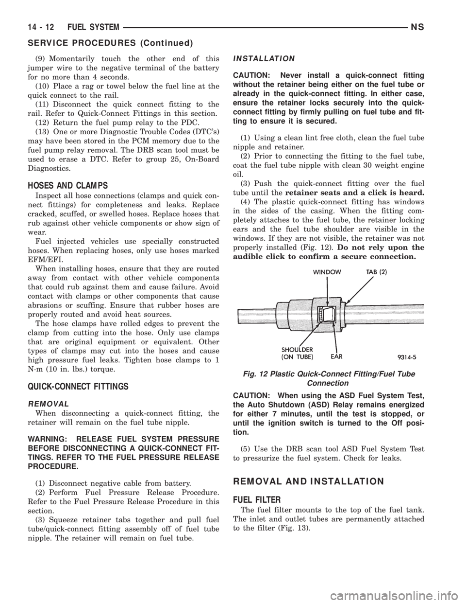
(4) The plastic quick-connect fitting has windows
in the sides of the casing. When the fitting com-
pletely attaches to the fuel tube, the retainer locking
ears and the fuel tube shoulder are visible in the
windows. If they are not visible, the retainer was not
properly installed (Fig. 12).Do not rely upon the
audible click to confirm a secure connection.
CAUTION: When using the ASD Fuel System Test,
the Auto Shutdown (ASD) Relay remains energized
for either 7 minutes, until the test is stopped, or
until the ignition switch is turned to the Off posi-
tion.
(5) Use the DRB scan tool ASD Fuel System Test
to pressurize the fuel system. Check for leaks.
REMOVAL AND INSTALLATION
FUEL FILTER
The fuel filter mounts to the top of the fuel tank.
The inlet and outlet tubes are permanently attached
to the filter (Fig. 13).
Fig. 12 Plastic Quick-Connect Fitting/Fuel Tube
Connection
14 - 12 FUEL SYSTEMNS
SERVICE PROCEDURES (Continued)