sensor CHRYSLER VOYAGER 1996 Service Manual
[x] Cancel search | Manufacturer: CHRYSLER, Model Year: 1996, Model line: VOYAGER, Model: CHRYSLER VOYAGER 1996Pages: 1938, PDF Size: 55.84 MB
Page 1356 of 1938
circuit information. If the resistance is greater than 1
ohm, repair the wire harness as necessary.
THROTTLE POSITION SENSOR
To perform a complete test of the this sensor and
its circuitry, refer to the DRB scan tool and appropri-
ate Powertrain Diagnostics Procedures manual. To
test the throttle position sensor only, refer to the fol-
lowing:
The Throttle Position Sensor (TPS) can be tested
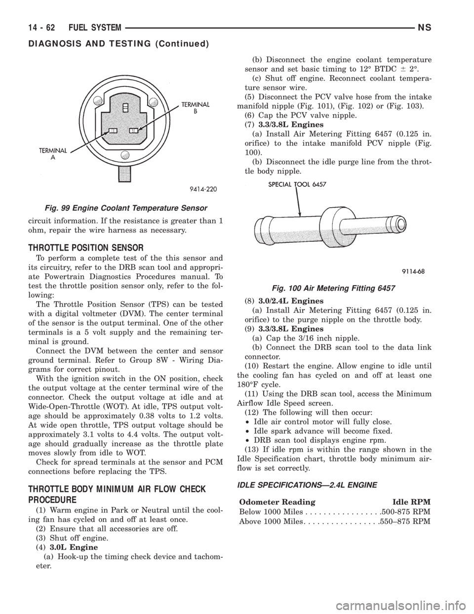
with a digital voltmeter (DVM). The center terminal
of the sensor is the output terminal. One of the other
terminals is a 5 volt supply and the remaining ter-
minal is ground.
Connect the DVM between the center and sensor
ground terminal. Refer to Group 8W - Wiring Dia-
grams for correct pinout.
With the ignition switch in the ON position, check
the output voltage at the center terminal wire of the
connector. Check the output voltage at idle and at
Wide-Open-Throttle (WOT). At idle, TPS output volt-
age should be approximately 0.38 volts to 1.2 volts.
At wide open throttle, TPS output voltage should be
approximately 3.1 volts to 4.4 volts. The output volt-
age should gradually increase as the throttle plate
moves slowly from idle to WOT.
Check for spread terminals at the sensor and PCM
connections before replacing the TPS.
THROTTLE BODY MINIMUM AIR FLOW CHECK
PROCEDURE
(1) Warm engine in Park or Neutral until the cool-
ing fan has cycled on and off at least once.
(2) Ensure that all accessories are off.
(3) Shut off engine.
(4)3.0L Engine
(a) Hook-up the timing check device and tachom-
eter.(b) Disconnect the engine coolant temperature
sensor and set basic timing to 12É BTDC62É.
(c) Shut off engine. Reconnect coolant tempera-
ture sensor wire.
(5) Disconnect the PCV valve hose from the intake
manifold nipple (Fig. 101), (Fig. 102) or (Fig. 103).
(6) Cap the PCV valve nipple.
(7)3.3/3.8L Engines
(a) Install Air Metering Fitting 6457 (0.125 in.
orifice) to the intake manifold PCV nipple (Fig.
100).
(b) Disconnect the idle purge line from the throt-
tle body nipple.
(8)3.0/2.4L Engines
(a) Install Air Metering Fitting 6457 (0.125 in.
orifice) to the purge nipple on the throttle body.
(9)3.3/3.8L Engines
(a) Cap the 3/16 inch nipple.
(b) Connect the DRB scan tool to the data link
connector.
(10) Restart the engine. Allow engine to idle until
the cooling fan has cycled on and off at least one
180ÉF cycle.
(11) Using the DRB scan tool, access the Minimum
Airflow Idle Speed screen.
(12) The following will then occur:
²Idle air control motor will fully close.
²Idle spark advance will become fixed.
²DRB scan tool displays engine rpm.
(13) If idle rpm is within the range shown in the
Idle Specification chart, throttle body minimum air-
flow is set correctly.
IDLE SPECIFICATIONSÐ2.4L ENGINE
Odometer Reading Idle RPM
Below 1000 Miles.................500-875 RPM
Above 1000 Miles.................550±875 RPM
Fig. 99 Engine Coolant Temperature Sensor
Fig. 100 Air Metering Fitting 6457
14 - 62 FUEL SYSTEMNS
DIAGNOSIS AND TESTING (Continued)
Page 1358 of 1938
REMOVAL AND INSTALLATION
THROTTLE BODY
REMOVAL
(1) Disconnect negative cable from battery cable.
(2) Remove air inlet to throttle body hose clamp.
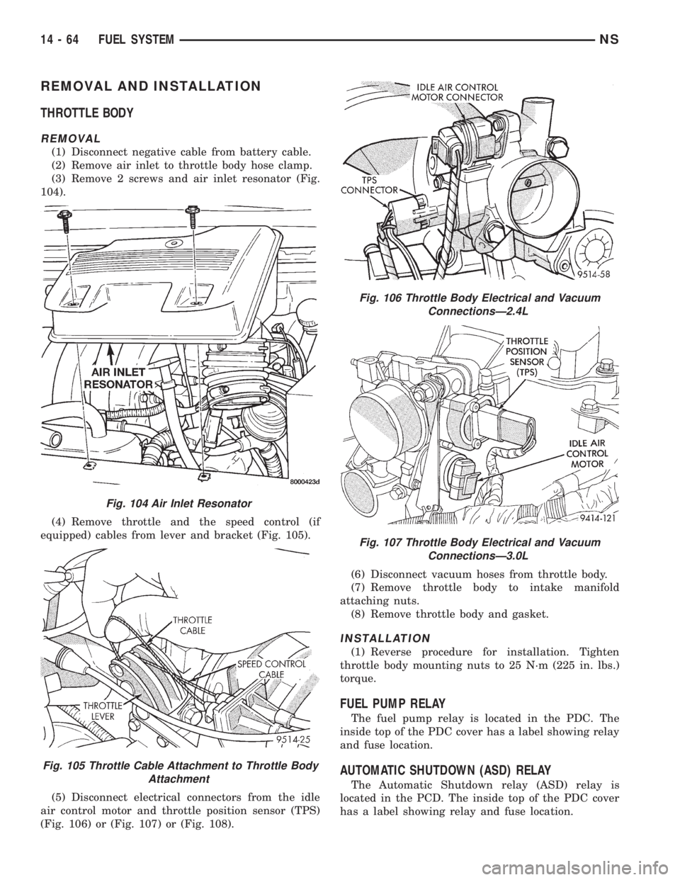
(3) Remove 2 screws and air inlet resonator (Fig.
104).
(4) Remove throttle and the speed control (if
equipped) cables from lever and bracket (Fig. 105).
(5) Disconnect electrical connectors from the idle
air control motor and throttle position sensor (TPS)
(Fig. 106) or (Fig. 107) or (Fig. 108).(6) Disconnect vacuum hoses from throttle body.
(7) Remove throttle body to intake manifold
attaching nuts.
(8) Remove throttle body and gasket.
INSTALLATION
(1) Reverse procedure for installation. Tighten
throttle body mounting nuts to 25 N´m (225 in. lbs.)
torque.
FUEL PUMP RELAY
The fuel pump relay is located in the PDC. The
inside top of the PDC cover has a label showing relay
and fuse location.
AUTOMATIC SHUTDOWN (ASD) RELAY
The Automatic Shutdown relay (ASD) relay is
located in the PCD. The inside top of the PDC cover
has a label showing relay and fuse location.
Fig. 104 Air Inlet Resonator
Fig. 105 Throttle Cable Attachment to Throttle Body
Attachment
Fig. 106 Throttle Body Electrical and Vacuum
ConnectionsÐ2.4L
Fig. 107 Throttle Body Electrical and Vacuum
ConnectionsÐ3.0L
14 - 64 FUEL SYSTEMNS
Page 1359 of 1938
THROTTLE POSITION SENSOR
REMOVAL
(1) Disconnect negative cable from battery.
(2) Remove electrical connector from throttle posi-
tion sensor.
(3) Remove throttle position sensor mounting
screws.
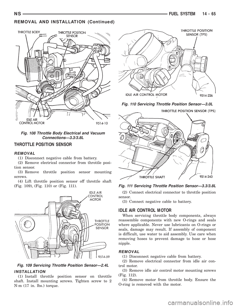
(4) Lift throttle position sensor off throttle shaft
(Fig. 109), (Fig. 110) or (Fig. 111).
INSTALLATION
(1) Install throttle position sensor on throttle
shaft. Install mounting screws. Tighten screw to 2
N´m (17 in. lbs.) torque.(2) Connect electrical connector to throttle position
sensor.
(3) Connect negative cable to battery.
IDLE AIR CONTROL MOTOR
When servicing throttle body components, always
reassemble components with new O-rings and seals
where applicable. Never use lubricants on O-rings or
seals, damage may result. If assembly of component
is difficult, use water to aid assembly. Use care when
removing hoses to prevent damage to hose or hose
nipple.
REMOVAL
(1) Disconnect negative cable from battery.
(2) Remove electrical connector from idle air con-
trol motor.
(3) Remove idle air control motor mounting screws
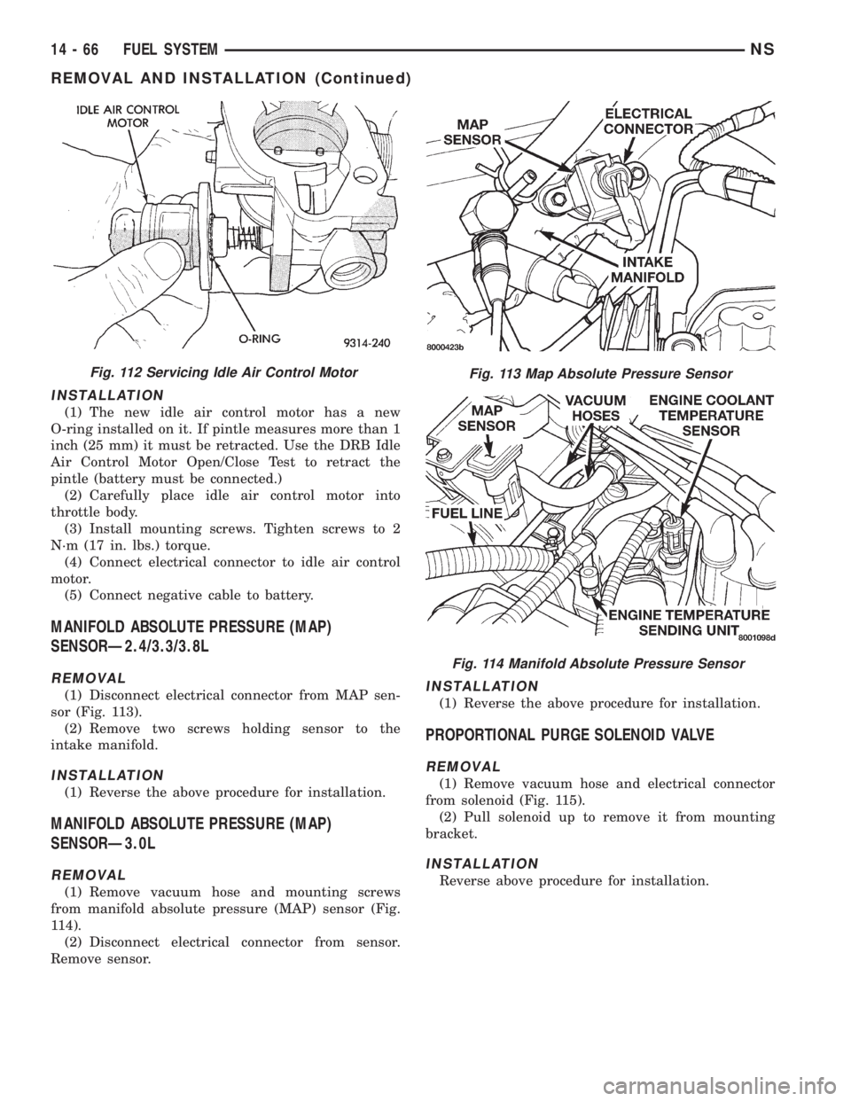
(Fig. 112).
(4) Remove motor from throttle body. Ensure the
O-ring is removed with the motor.
Fig. 108 Throttle Body Electrical and Vacuum
ConnectionsÐ3.3/3.8L
Fig. 109 Servicing Throttle Position SensorÐ2.4L
Fig. 110 Servicing Throttle Position SensorÐ3.0L
Fig. 111 Servicing Throttle Position SensorÐ3.3/3.8L
NSFUEL SYSTEM 14 - 65
REMOVAL AND INSTALLATION (Continued)
Page 1360 of 1938
INSTALLATION
(1) The new idle air control motor has a new
O-ring installed on it. If pintle measures more than 1
inch (25 mm) it must be retracted. Use the DRB Idle
Air Control Motor Open/Close Test to retract the
pintle (battery must be connected.)
(2) Carefully place idle air control motor into
throttle body.
(3) Install mounting screws. Tighten screws to 2
N´m (17 in. lbs.) torque.
(4) Connect electrical connector to idle air control
motor.
(5) Connect negative cable to battery.
MANIFOLD ABSOLUTE PRESSURE (MAP)
SENSORÐ2.4/3.3/3.8L
REMOVAL
(1) Disconnect electrical connector from MAP sen-
sor (Fig. 113).
(2) Remove two screws holding sensor to the
intake manifold.
INSTALLATION
(1) Reverse the above procedure for installation.
MANIFOLD ABSOLUTE PRESSURE (MAP)
SENSORÐ3.0L
REMOVAL
(1) Remove vacuum hose and mounting screws
from manifold absolute pressure (MAP) sensor (Fig.
114).
(2) Disconnect electrical connector from sensor.
Remove sensor.
INSTALLATION
(1) Reverse the above procedure for installation.
PROPORTIONAL PURGE SOLENOID VALVE
REMOVAL
(1) Remove vacuum hose and electrical connector
from solenoid (Fig. 115).
(2) Pull solenoid up to remove it from mounting
bracket.
INSTALLATION
Reverse above procedure for installation.
Fig. 112 Servicing Idle Air Control MotorFig. 113 Map Absolute Pressure Sensor
Fig. 114 Manifold Absolute Pressure Sensor
14 - 66 FUEL SYSTEMNS
REMOVAL AND INSTALLATION (Continued)
Page 1362 of 1938
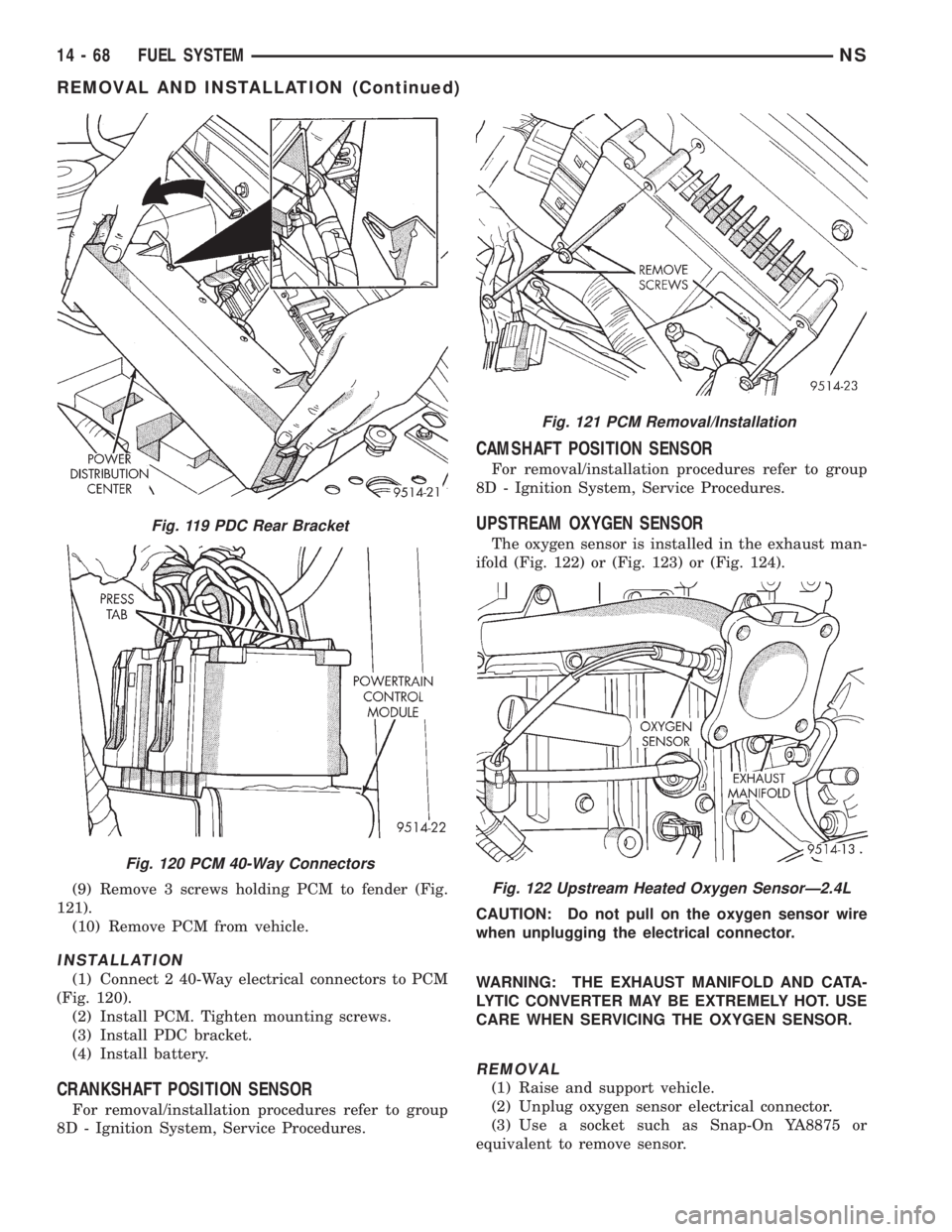
(9) Remove 3 screws holding PCM to fender (Fig.
121).
(10) Remove PCM from vehicle.
INSTALLATION
(1) Connect 2 40-Way electrical connectors to PCM
(Fig. 120).
(2) Install PCM. Tighten mounting screws.
(3) Install PDC bracket.
(4) Install battery.
CRANKSHAFT POSITION SENSOR
For removal/installation procedures refer to group
8D - Ignition System, Service Procedures.
CAMSHAFT POSITION SENSOR
For removal/installation procedures refer to group
8D - Ignition System, Service Procedures.
UPSTREAM OXYGEN SENSOR
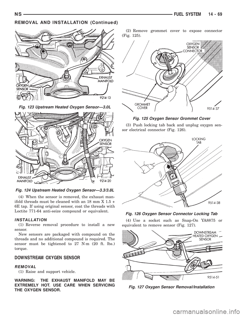
The oxygen sensor is installed in the exhaust man-
ifold (Fig. 122) or (Fig. 123) or (Fig. 124).
CAUTION: Do not pull on the oxygen sensor wire
when unplugging the electrical connector.
WARNING: THE EXHAUST MANIFOLD AND CATA-
LYTIC CONVERTER MAY BE EXTREMELY HOT. USE
CARE WHEN SERVICING THE OXYGEN SENSOR.
REMOVAL
(1) Raise and support vehicle.
(2) Unplug oxygen sensor electrical connector.
(3) Use a socket such as Snap-On YA8875 or
equivalent to remove sensor.
Fig. 119 PDC Rear Bracket
Fig. 120 PCM 40-Way Connectors
Fig. 121 PCM Removal/Installation
Fig. 122 Upstream Heated Oxygen SensorÐ2.4L
14 - 68 FUEL SYSTEMNS
REMOVAL AND INSTALLATION (Continued)
Page 1363 of 1938
(4) When the sensor is removed, the exhaust man-
ifold threads must be cleaned with an 18 mm X 1.5 +
6E tap. If using original sensor, coat the threads with
Loctite 771-64 anti-seize compound or equivalent.
INSTALLATION
(1) Reverse removal procedure to install a new
sensor.
New sensors are packaged with compound on the
threads and no additional compound is required. The
sensor must be tightened to 27 N´m (20 ft. lbs.)
torque.
DOWNSTREAM OXYGEN SENSOR
REMOVAL
(1) Raise and support vehicle.
WARNING: THE EXHAUST MANIFOLD MAY BE
EXTREMELY HOT. USE CARE WHEN SERVICING
THE OXYGEN SENSOR.(2) Remove grommet cover to expose connector
(Fig. 125).
(3) Push locking tab back and unplug oxygen sen-
sor electrical connector (Fig. 126).
(4) Use a socket such as Snap-On YA8875 or
equivalent to remove sensor (Fig. 127).
Fig. 123 Upstream Heated Oxygen SensorÐ3.0L
Fig. 124 Upstream Heated Oxygen SensorÐ3.3/3.8L
Fig. 125 Oxygen Sensor Grommet Cover
Fig. 126 Oxygen Sensor Connector Locking Tab
Fig. 127 Oxygen Sensor Removal/Installation
NSFUEL SYSTEM 14 - 69
REMOVAL AND INSTALLATION (Continued)
Page 1364 of 1938
(5) When the sensor is removed, the exhaust man-
ifold threads must be cleaned with an 18 mm X 1.5 +
6E tap. If using original sensor, coat the threads with
Loctite 771-64 anti-seize compound or equivalent.
INSTALLATION
(1) Reverse removal procedure to install a new
sensor.
New sensors are packaged with compound on the
threads and no additional compound is required. The
sensor must be tightened to 27 N´m (20 ft. lbs.)
torque.
KNOCK SENSOR
For removal/installation procedures refer to Group
8D- Ignition System, Service Procedures.
AIR CLEANER ELEMENT
REMOVAL
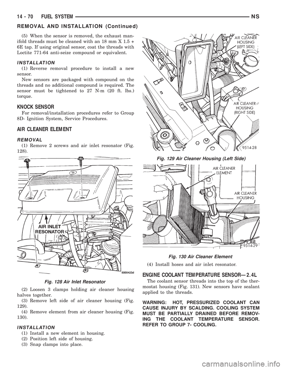
(1) Remove 2 screws and air inlet resonator (Fig.
128).
(2) Loosen 3 clamps holding air cleaner housing
halves together.
(3) Remove left side of air cleaner housing (Fig.
129).
(4) Remove element from air cleaner housing (Fig.
130).
INSTALLATION
(1) Install a new element in housing.
(2) Position left side of housing.
(3) Snap clamps into place.(4) Install hoses and air inlet resonator.
ENGINE COOLANT TEMPERATURE SENSORÐ2.4L
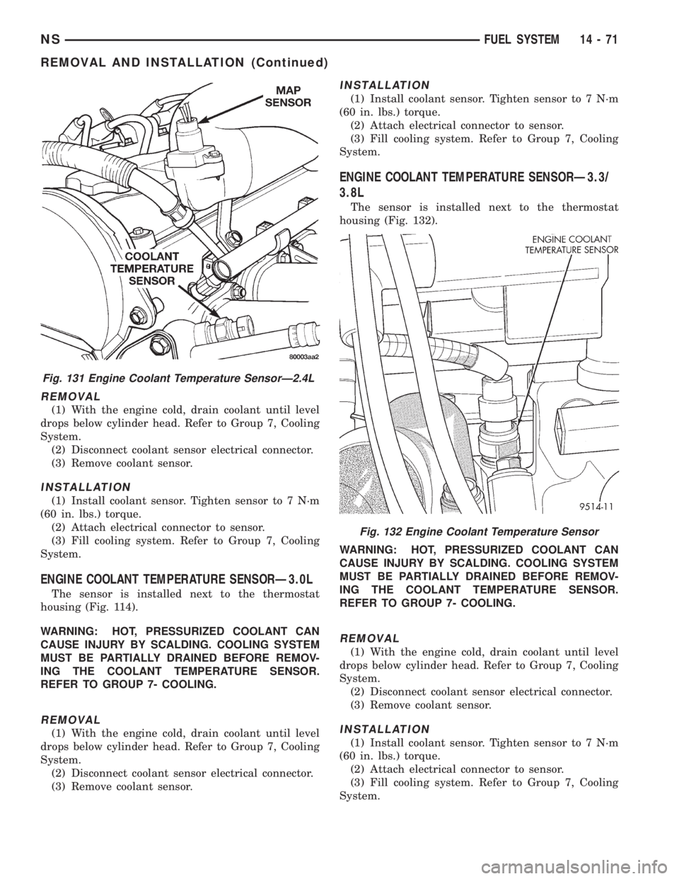
The coolant sensor threads into the top of the ther-
mostat housing (Fig. 131). New sensors have sealant
applied to the threads.
WARNING: HOT, PRESSURIZED COOLANT CAN
CAUSE INJURY BY SCALDING. COOLING SYSTEM
MUST BE PARTIALLY DRAINED BEFORE REMOV-
ING THE COOLANT TEMPERATURE SENSOR.
REFER TO GROUP 7- COOLING.Fig. 128 Air Inlet Resonator
Fig. 129 Air Cleaner Housing (Left Side)
Fig. 130 Air Cleaner Element
14 - 70 FUEL SYSTEMNS
REMOVAL AND INSTALLATION (Continued)
Page 1365 of 1938
REMOVAL
(1) With the engine cold, drain coolant until level
drops below cylinder head. Refer to Group 7, Cooling
System.
(2) Disconnect coolant sensor electrical connector.
(3) Remove coolant sensor.
INSTALLATION
(1) Install coolant sensor. Tighten sensor to 7 N´m
(60 in. lbs.) torque.
(2) Attach electrical connector to sensor.
(3) Fill cooling system. Refer to Group 7, Cooling
System.
ENGINE COOLANT TEMPERATURE SENSORÐ3.0L
The sensor is installed next to the thermostat
housing (Fig. 114).
WARNING: HOT, PRESSURIZED COOLANT CAN
CAUSE INJURY BY SCALDING. COOLING SYSTEM
MUST BE PARTIALLY DRAINED BEFORE REMOV-
ING THE COOLANT TEMPERATURE SENSOR.
REFER TO GROUP 7- COOLING.
REMOVAL
(1) With the engine cold, drain coolant until level
drops below cylinder head. Refer to Group 7, Cooling
System.
(2) Disconnect coolant sensor electrical connector.
(3) Remove coolant sensor.
INSTALLATION
(1) Install coolant sensor. Tighten sensor to 7 N´m
(60 in. lbs.) torque.
(2) Attach electrical connector to sensor.
(3) Fill cooling system. Refer to Group 7, Cooling
System.
ENGINE COOLANT TEMPERATURE SENSORÐ3.3/
3.8L
The sensor is installed next to the thermostat
housing (Fig. 132).
WARNING: HOT, PRESSURIZED COOLANT CAN
CAUSE INJURY BY SCALDING. COOLING SYSTEM
MUST BE PARTIALLY DRAINED BEFORE REMOV-
ING THE COOLANT TEMPERATURE SENSOR.
REFER TO GROUP 7- COOLING.
REMOVAL
(1) With the engine cold, drain coolant until level
drops below cylinder head. Refer to Group 7, Cooling
System.
(2) Disconnect coolant sensor electrical connector.
(3) Remove coolant sensor.
INSTALLATION
(1) Install coolant sensor. Tighten sensor to 7 N´m
(60 in. lbs.) torque.
(2) Attach electrical connector to sensor.
(3) Fill cooling system. Refer to Group 7, Cooling
System.
Fig. 131 Engine Coolant Temperature SensorÐ2.4L
Fig. 132 Engine Coolant Temperature Sensor
NSFUEL SYSTEM 14 - 71
REMOVAL AND INSTALLATION (Continued)
Page 1366 of 1938
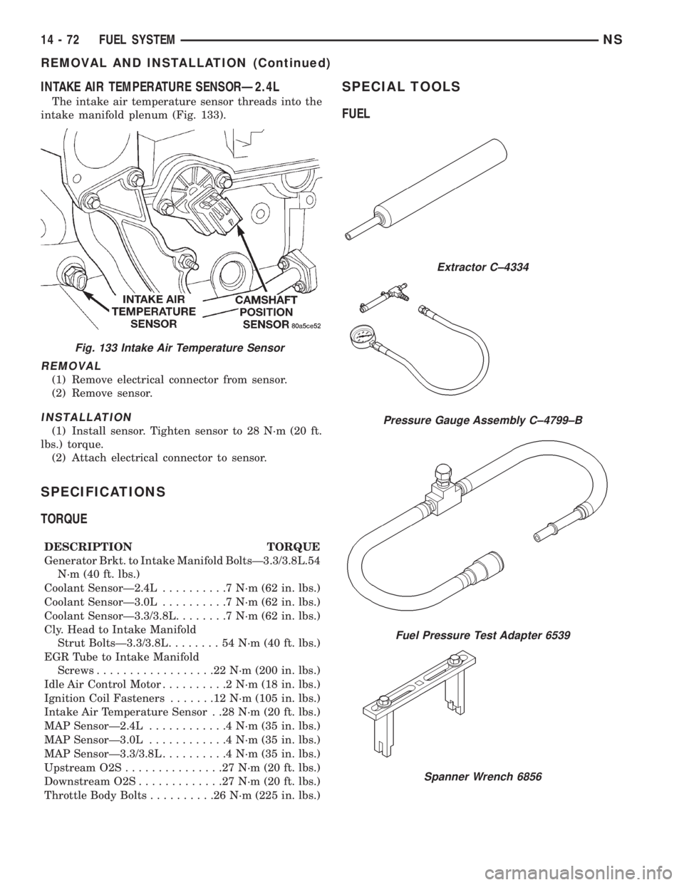
INTAKE AIR TEMPERATURE SENSORÐ2.4L
The intake air temperature sensor threads into the
intake manifold plenum (Fig. 133).
REMOVAL
(1) Remove electrical connector from sensor.
(2) Remove sensor.
INSTALLATION
(1) Install sensor. Tighten sensor to 28 N´m (20 ft.
lbs.) torque.
(2) Attach electrical connector to sensor.
SPECIFICATIONS
TORQUE
DESCRIPTION TORQUE
Generator Brkt. to Intake Manifold BoltsÐ3.3/3.8L.54
N´m (40 ft. lbs.)
Coolant SensorÐ2.4L..........7N´m(62in.lbs.)
Coolant SensorÐ3.0L..........7N´m(62in.lbs.)
Coolant SensorÐ3.3/3.8L........7N´m(62in.lbs.)
Cly. Head to Intake Manifold
Strut BoltsÐ3.3/3.8L........54N´m(40ft.lbs.)
EGR Tube to Intake Manifold
Screws..................22N´m(200 in. lbs.)
Idle Air Control Motor..........2N´m(18in.lbs.)
Ignition Coil Fasteners.......12N´m(105 in. lbs.)
Intake Air Temperature Sensor . .28 N´m (20 ft. lbs.)
MAP SensorÐ2.4L............4N´m(35in.lbs.)
MAP SensorÐ3.0L............4N´m(35in.lbs.)
MAP SensorÐ3.3/3.8L..........4N´m(35in.lbs.)
Upstream O2S...............27N´m(20ft.lbs.)
Downstream O2S.............27N´m(20ft.lbs.)
Throttle Body Bolts..........26N´m(225 in. lbs.)
SPECIAL TOOLS
FUEL
Fig. 133 Intake Air Temperature Sensor
Extractor C±4334
Pressure Gauge Assembly C±4799±B
Fuel Pressure Test Adapter 6539
Spanner Wrench 6856
14 - 72 FUEL SYSTEMNS
REMOVAL AND INSTALLATION (Continued)
Page 1367 of 1938
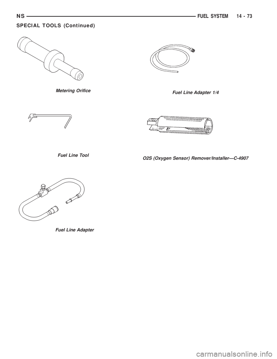
Metering Orifice
Fuel Line Tool
Fuel Line Adapter
Fuel Line Adapter 1/4
O2S (Oxygen Sensor) Remover/InstallerÐC-4907
NSFUEL SYSTEM 14 - 73
SPECIAL TOOLS (Continued)