sensor CHRYSLER VOYAGER 1996 Service Manual
[x] Cancel search | Manufacturer: CHRYSLER, Model Year: 1996, Model line: VOYAGER, Model: CHRYSLER VOYAGER 1996Pages: 1938, PDF Size: 55.84 MB
Page 1371 of 1938
FUEL DELIVERY SYSTEMÐ2.5L DIESEL ENGINE
INDEX
page page
DESCRIPTION AND OPERATION
FUEL DRAIN TUBES..................... 7
FUEL FILTER/WATER SEPARATOR.......... 4
FUEL GAUGE SENDING UNIT.............. 4
FUEL HEATER RELAY.................... 8
FUEL HEATER.......................... 8
FUEL INJECTION PUMP.................. 5
FUEL INJECTORS....................... 6
FUEL SHUTDOWN SOLENOID............. 5
FUEL SYSTEM PRESSURE WARNING....... 3
FUEL TANK MODULE.................... 4
FUEL TANK............................ 3
FUEL TUBES/LINES/HOSES AND CLAMPSÐ
LOW-PRESSURE TYPE................. 6
HIGH-PRESSURE FUEL LINES............. 7
INTRODUCTION........................ 3
QUICK-CONNECT FITTINGSÐLOW PRESSURE
TYPE............................... 7
WASTEGATE (TURBOCHARGER)........... 8
DIAGNOSIS AND TESTING
AIR IN FUEL SYSTEM................... 11
FUEL HEATER RELAY TEST.............. 12
FUEL INJECTION PUMP TEST............. 12
FUEL INJECTOR SENSOR TEST........... 12
FUEL INJECTOR TEST.................. 12
FUEL SHUTDOWN SOLENOID TEST........ 13
FUEL SUPPLY RESTRICTIONS............ 13GENERAL INFORMATION................. 9
HIGH-PRESSURE FUEL LINE LEAK TEST.... 14
VISUAL INSPECTION..................... 9
WASTEGATE (TURBOCHARGER).......... 14
SERVICE PROCEDURES
AIR BLEED PROCEDURES............... 14
FUEL INJECTION PUMP TIMING........... 15
REMOVAL AND INSTALLATION
ACCELERATOR PEDAL.................. 16
AIR CLEANER ELEMENT................. 16
FUEL DRAIN TUBES.................... 16
FUEL FILTER/WATER SEPARATOR......... 16
FUEL HEATER RELAY................... 17
FUEL HEATER......................... 17
FUEL INJECTION PUMP................. 19
FUEL INJECTORS...................... 22
FUEL LEVEL SENSOR................... 18
FUEL RESERVOIR MODULE.............. 25
FUEL SHUTDOWN SOLENOID............ 23
FUEL TANK........................... 23
HIGH-PRESSURE LINES................. 26
SPECIFICATIONS
FUEL INJECTOR FIRING SEQUENCE....... 27
FUEL SYSTEM PRESSURE............... 27
FUEL TANK CAPACITY.................. 27
IDLE SPEED.......................... 27
DESCRIPTION AND OPERATION
INTRODUCTION
This Fuel Delivery section will cover components
not controlled by the PCM. For components con-
trolled by the PCM, refer to the Fuel Injection Sys-
temÐ2.5L Diesel Engine section of this group.
The fuel heater relay, fuel heater and fuel gauge
are not operated by the PCM. These components are
controlled by the ignition (key) switch. All other fuel
system electrical components necessary to operate
the engine are controlled or regulated by the PCM.
FUEL SYSTEM PRESSURE WARNING
WARNING: HIGH±PRESSURE FUEL LINES DELIVER
DIESEL FUEL UNDER EXTREME PRESSURE FROM
THE INJECTION PUMP TO THE FUEL INJECTORS.
THIS MAY BE AS HIGH AS 45,000 KPA (6526 PSI).
USE EXTREME CAUTION WHEN INSPECTING FORHIGH±PRESSURE FUEL LEAKS. INSPECT FOR
HIGH±PRESSURE FUEL LEAKS WITH A SHEET OF
CARDBOARD (Fig. 1). HIGH FUEL INJECTION
PRESSURE CAN CAUSE PERSONAL INJURY IF
CONTACT IS MADE WITH THE SKIN.
FUEL TANK
The fuel tank and tank mounting used with the
diesel powered engine is the same as used with gas-
oline powered models, although the fuel tank module
is different.
The fuel tank contains the fuel tank module and
two rollover valves. Two fuel lines are routed to the
fuel tank module. One line is used for fuel supply to
the fuel filter/water separator. The other is used to
return excess fuel back to the fuel tank.
The fuel tank module contains the fuel gauge elec-
trical sending unit.An electrical fuel pump is not
used with the diesel engine.
NS/GSFUEL SYSTEMÐ2.5L DIESEL ENGINE/2.0L GAS ENGINE 14 - 3
Page 1373 of 1938
For periodic draining of water from the bowl, refer
to Fuel Filter/Water Separator Removal/Installation
in this group.
FUEL SHUTDOWN SOLENOID
The fuel shutdown solenoid is controlled and
operated by the PCM.
The fuel shutdown (shut-off) solenoid is used to
electrically shut off the diesel fuel supply to the high-
pressure fuel injection pump. The solenoid is
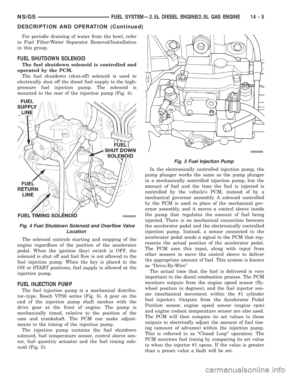
mounted to the rear of the injection pump (Fig. 4).
The solenoid controls starting and stopping of the
engine regardless of the position of the accelerator
pedal. When the ignition (key) switch is OFF, the
solenoid is shut off and fuel flow is not allowed to the
fuel injection pump. When the key is placed in the
ON or START positions, fuel supply is allowed at the
injection pump.
FUEL INJECTION PUMP
The fuel injection pump is a mechanical distribu-
tor±type, Bosch VP36 series (Fig. 5). A gear on the
end of the injection pump shaft meshes with the
drive gear at the front of engine. The pump is
mechanically timed, relative to the position of the
cam and crankshaft. The PCM can make adjust-
ments to the timing of the injection pump.
The injection pump contains the fuel shutdown
solenoid, fuel temperature sensor, control sleeve sen-
sor, fuel quantity actuator and the fuel timing sole-
noid (Fig. 5).In the electronically controlled injection pump, the
pump plunger works the same as the pump plunger
in a mechanically controlled injection pump, but the
amount of fuel and the time the fuel is injected is
controlled by the vehicle's PCM, instead of by a
mechanical governor assembly. A solenoid controlled
by the PCM is used in place of the mechanical gov-
ernor assembly, and it moves a control sleeve inside
the pump that regulates the amount of fuel being
injected. There is no mechanical connection between
the accelerator pedal and the electronically controlled
injection pump. Instead, a sensor connected to the
accelerator pedal sends a signal to the PCM that rep-
resents the actual position of the accelerator pedal.
The PCM uses this input, along with input from
other sensors to move the control sleeve to deliver
the appropriate amount of fuel. This system is known
as ªDrive-By-Wireº
The actual time that the fuel is delivered is very
important to the diesel combustion process. The PCM
monitors outputs from the engine speed sensor (fly-
wheel position in degrees), and the fuel injector sen-
sor (mechanical movement within the #1 cylinder
fuel injector). Outputs from the Accelerator Pedal
Position sensor, engine speed sensor (engine rpm)
and engine coolant temperature sensor are also used.
The PCM will then compare its set values to these
outputs to electrically adjust the amount of fuel tim-
ing (amount of advance) within the injection pump.
This is referred to as ªClosed Loopº operation. The
PCM monitors fuel timing by comparing its set value
to when the injector #1 opens. If the value is greater
than a preset value a fault will be set.
Fig. 4 Fuel Shutdown Solenoid and Overflow Valve
Location
Fig. 5 Fuel Injection Pump
NS/GSFUEL SYSTEMÐ2.5L DIESEL ENGINE/2.0L GAS ENGINE 14 - 5
DESCRIPTION AND OPERATION (Continued)
Page 1374 of 1938
Actual electric fuel timing (amount of advance) is
accomplished by the fuel timing solenoid mounted to
the bottom of the injection pump (Fig. 5). Fuel timing
will be adjusted by the PCM, which controls the fuel
timing solenoid.
An overflow valve is attached into the fuel return
line at the rear of the fuel injection pump (Fig. 4).
This valve serves two purposes. One is to ensure that
a certain amount of residual pressure is maintained
within the pump when the engine is switched off.
This will prevent the fuel timing mechanism within
the injection pump from returning to its zero posi-
tion. The other purpose is to allow excess fuel to be
returned to the fuel tank through the fuel return
line. The pressure values within this valve are preset
and can not be adjusted.
The fuel injection pump supplies high±pressure
fuel of approximately 45,000 kPa (6526 psi) to each
injector in precise metered amounts at the correct
time.
For mechanical injection pump timing, refer to
Fuel Injection Pump Timing in the Service Proce-
dures section of this group.
FUEL INJECTORS
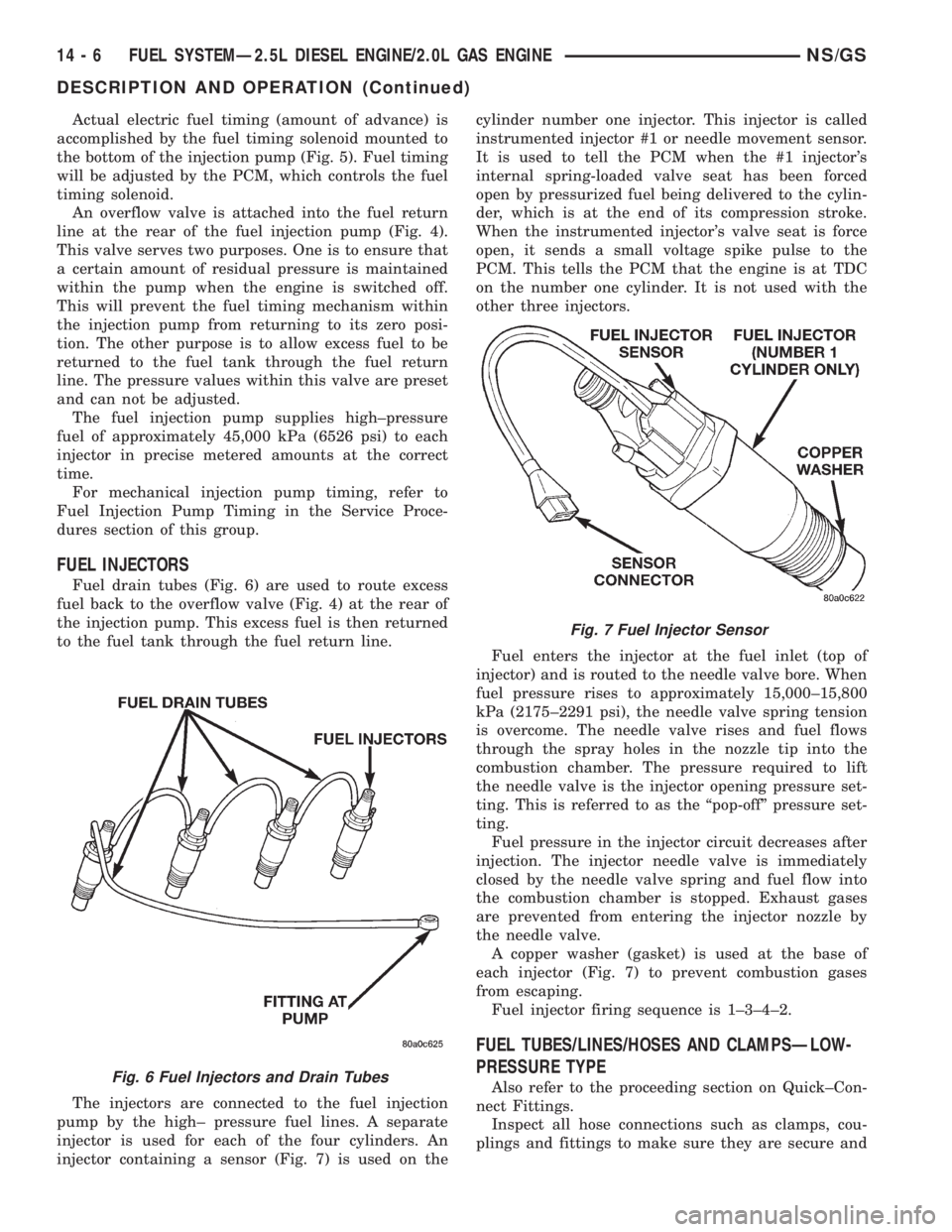
Fuel drain tubes (Fig. 6) are used to route excess
fuel back to the overflow valve (Fig. 4) at the rear of
the injection pump. This excess fuel is then returned
to the fuel tank through the fuel return line.
The injectors are connected to the fuel injection
pump by the high± pressure fuel lines. A separate
injector is used for each of the four cylinders. An
injector containing a sensor (Fig. 7) is used on thecylinder number one injector. This injector is called
instrumented injector #1 or needle movement sensor.
It is used to tell the PCM when the #1 injector's
internal spring-loaded valve seat has been forced
open by pressurized fuel being delivered to the cylin-
der, which is at the end of its compression stroke.
When the instrumented injector's valve seat is force
open, it sends a small voltage spike pulse to the
PCM. This tells the PCM that the engine is at TDC
on the number one cylinder. It is not used with the
other three injectors.
Fuel enters the injector at the fuel inlet (top of
injector) and is routed to the needle valve bore. When
fuel pressure rises to approximately 15,000±15,800
kPa (2175±2291 psi), the needle valve spring tension
is overcome. The needle valve rises and fuel flows
through the spray holes in the nozzle tip into the
combustion chamber. The pressure required to lift
the needle valve is the injector opening pressure set-
ting. This is referred to as the ªpop-offº pressure set-
ting.
Fuel pressure in the injector circuit decreases after
injection. The injector needle valve is immediately
closed by the needle valve spring and fuel flow into
the combustion chamber is stopped. Exhaust gases
are prevented from entering the injector nozzle by
the needle valve.
A copper washer (gasket) is used at the base of
each injector (Fig. 7) to prevent combustion gases
from escaping.
Fuel injector firing sequence is 1±3±4±2.
FUEL TUBES/LINES/HOSES AND CLAMPSÐLOW-
PRESSURE TYPE
Also refer to the proceeding section on Quick±Con-
nect Fittings.
Inspect all hose connections such as clamps, cou-
plings and fittings to make sure they are secure andFig. 6 Fuel Injectors and Drain Tubes
Fig. 7 Fuel Injector Sensor
14 - 6 FUEL SYSTEMÐ2.5L DIESEL ENGINE/2.0L GAS ENGINENS/GS
DESCRIPTION AND OPERATION (Continued)
Page 1376 of 1938
FUEL HEATER
The fuel heater is used to prevent diesel fuel from
waxing during cold weather operation. The fuel
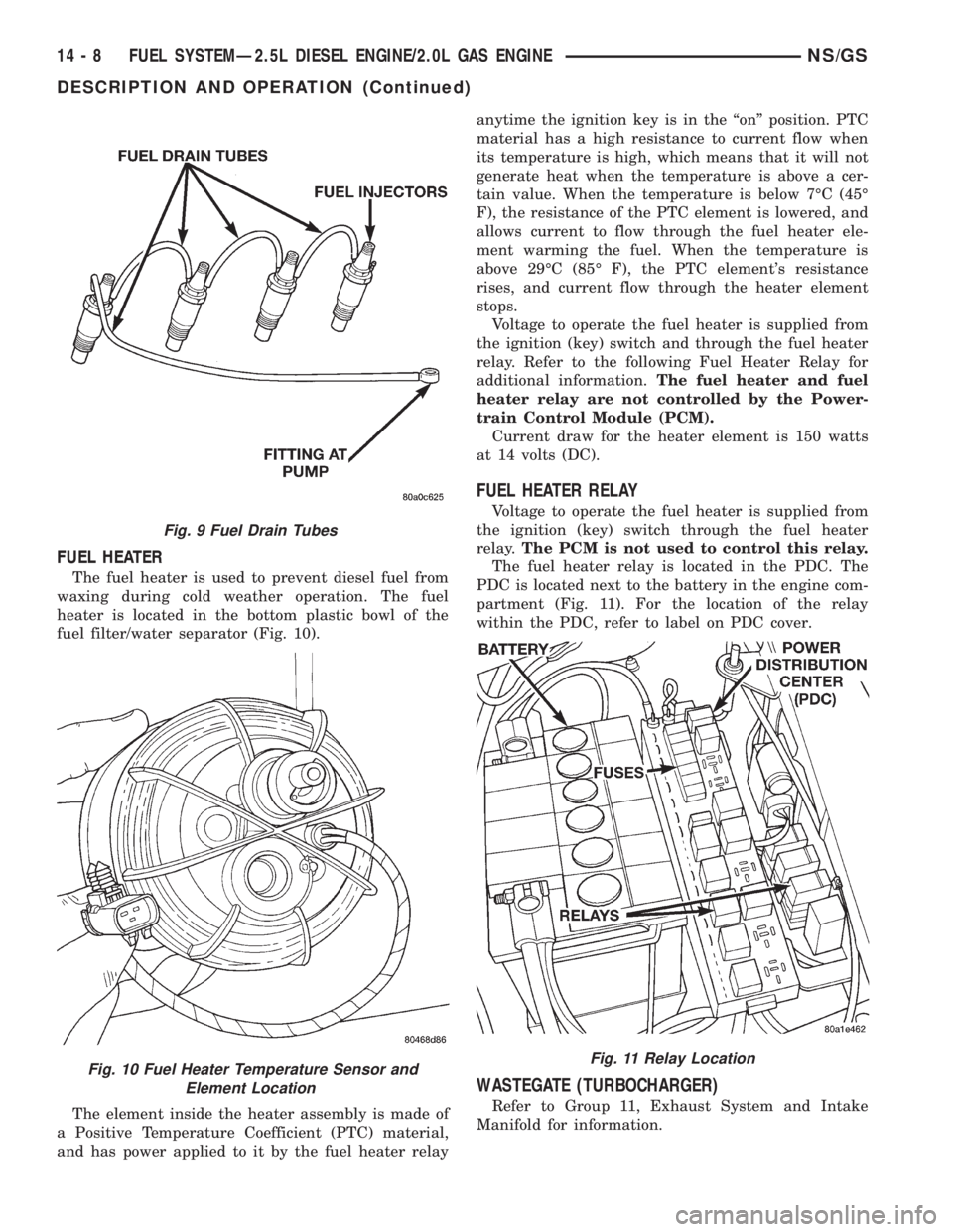
heater is located in the bottom plastic bowl of the
fuel filter/water separator (Fig. 10).
The element inside the heater assembly is made of
a Positive Temperature Coefficient (PTC) material,
and has power applied to it by the fuel heater relayanytime the ignition key is in the ªonº position. PTC
material has a high resistance to current flow when
its temperature is high, which means that it will not
generate heat when the temperature is above a cer-
tain value. When the temperature is below 7ÉC (45É
F), the resistance of the PTC element is lowered, and
allows current to flow through the fuel heater ele-
ment warming the fuel. When the temperature is
above 29ÉC (85É F), the PTC element's resistance
rises, and current flow through the heater element
stops.
Voltage to operate the fuel heater is supplied from
the ignition (key) switch and through the fuel heater
relay. Refer to the following Fuel Heater Relay for
additional information.The fuel heater and fuel
heater relay are not controlled by the Power-
train Control Module (PCM).
Current draw for the heater element is 150 watts
at 14 volts (DC).
FUEL HEATER RELAY
Voltage to operate the fuel heater is supplied from
the ignition (key) switch through the fuel heater
relay.The PCM is not used to control this relay.
The fuel heater relay is located in the PDC. The
PDC is located next to the battery in the engine com-
partment (Fig. 11). For the location of the relay
within the PDC, refer to label on PDC cover.
WASTEGATE (TURBOCHARGER)
Refer to Group 11, Exhaust System and Intake
Manifold for information.
Fig. 9 Fuel Drain Tubes
Fig. 10 Fuel Heater Temperature Sensor and
Element LocationFig. 11 Relay Location
14 - 8 FUEL SYSTEMÐ2.5L DIESEL ENGINE/2.0L GAS ENGINENS/GS
DESCRIPTION AND OPERATION (Continued)
Page 1378 of 1938
(7) Inspect the starter motor and starter solenoid
connections for tightness and corrosion.
(8) Verify that the electrical connector is firmly
connected to the fuel shutdown solenoid. Inspect the
connector for corrosion or damaged wires. The sole-
noid is mounted to the rear of the injection pump
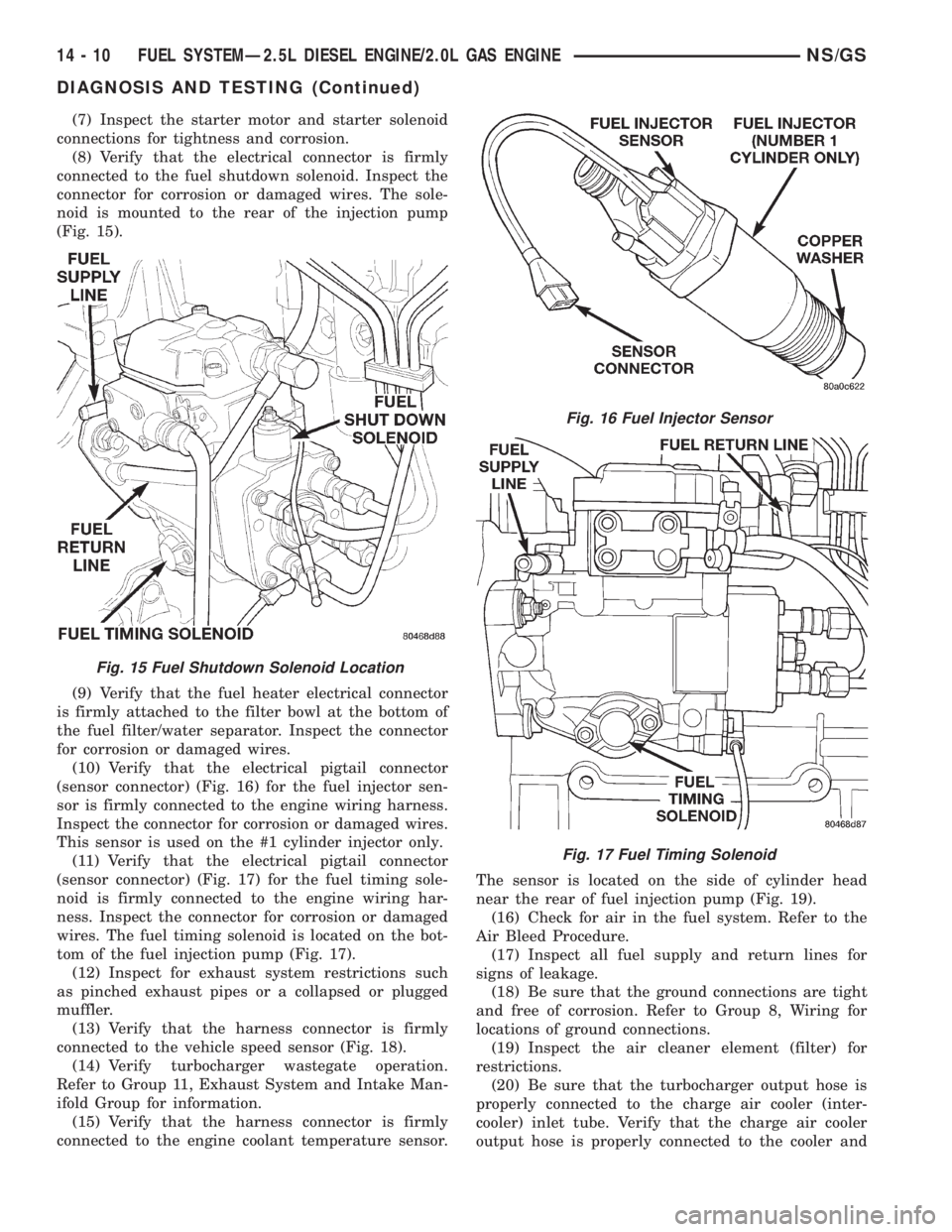
(Fig. 15).
(9) Verify that the fuel heater electrical connector
is firmly attached to the filter bowl at the bottom of
the fuel filter/water separator. Inspect the connector
for corrosion or damaged wires.
(10) Verify that the electrical pigtail connector
(sensor connector) (Fig. 16) for the fuel injector sen-
sor is firmly connected to the engine wiring harness.
Inspect the connector for corrosion or damaged wires.
This sensor is used on the #1 cylinder injector only.
(11) Verify that the electrical pigtail connector
(sensor connector) (Fig. 17) for the fuel timing sole-
noid is firmly connected to the engine wiring har-
ness. Inspect the connector for corrosion or damaged
wires. The fuel timing solenoid is located on the bot-
tom of the fuel injection pump (Fig. 17).
(12) Inspect for exhaust system restrictions such
as pinched exhaust pipes or a collapsed or plugged
muffler.
(13) Verify that the harness connector is firmly
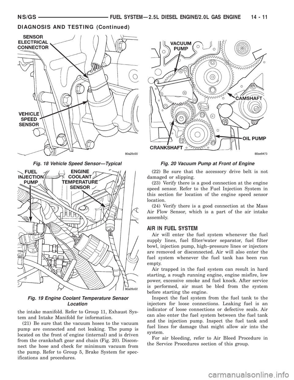
connected to the vehicle speed sensor (Fig. 18).
(14) Verify turbocharger wastegate operation.
Refer to Group 11, Exhaust System and Intake Man-
ifold Group for information.
(15) Verify that the harness connector is firmly
connected to the engine coolant temperature sensor.The sensor is located on the side of cylinder head
near the rear of fuel injection pump (Fig. 19).
(16) Check for air in the fuel system. Refer to the
Air Bleed Procedure.
(17) Inspect all fuel supply and return lines for
signs of leakage.
(18) Be sure that the ground connections are tight
and free of corrosion. Refer to Group 8, Wiring for
locations of ground connections.
(19) Inspect the air cleaner element (filter) for
restrictions.
(20) Be sure that the turbocharger output hose is
properly connected to the charge air cooler (inter-
cooler) inlet tube. Verify that the charge air cooler
output hose is properly connected to the cooler and
Fig. 15 Fuel Shutdown Solenoid Location
Fig. 16 Fuel Injector Sensor
Fig. 17 Fuel Timing Solenoid
14 - 10 FUEL SYSTEMÐ2.5L DIESEL ENGINE/2.0L GAS ENGINENS/GS
DIAGNOSIS AND TESTING (Continued)
Page 1379 of 1938
the intake manifold. Refer to Group 11, Exhaust Sys-
tem and Intake Manifold for information.
(21) Be sure that the vacuum hoses to the vacuum
pump are connected and not leaking. The pump is
located on the front of engine (internal) and is driven
from the crankshaft gear and chain (Fig. 20). Discon-
nect the hose and check for minimum vacuum from
the pump. Refer to Group 5, Brake System for spec-
ifications and procedures.(22) Be sure that the accessory drive belt is not
damaged or slipping.
(23) Verify there is a good connection at the engine
speed sensor. Refer to the Fuel Injection System in
this section for location of the engine speed sensor
location.
(24) Verify there is a good connection at the Mass
Air Flow Sensor, which is a part of the air intake
assembly.
AIR IN FUEL SYSTEM
Air will enter the fuel system whenever the fuel
supply lines, fuel filter/water separator, fuel filter
bowl, injection pump, high±pressure lines or injectors
are removed or disconnected. Air will also enter the
fuel system whenever the fuel tank has been run
empty.
Air trapped in the fuel system can result in hard
starting, a rough running engine, engine misfire, low
power, excessive smoke and fuel knock. After service
is performed, air must be bled from the system
before starting the engine.
Inspect the fuel system from the fuel tank to the
injectors for loose connections. Leaking fuel is an
indicator of loose connections or defective seals. Air
can also enter the fuel system between the fuel tank
and the injection pump. Inspect the fuel tank and
fuel lines for damage that might allow air into the
system.
For air bleeding, refer to Air Bleed Procedure in
the Service Procedures section of this group.
Fig. 18 Vehicle Speed SensorÐTypical
Fig. 19 Engine Coolant Temperature Sensor
Location
Fig. 20 Vacuum Pump at Front of Engine
NS/GSFUEL SYSTEMÐ2.5L DIESEL ENGINE/2.0L GAS ENGINE 14 - 11
DIAGNOSIS AND TESTING (Continued)
Page 1380 of 1938
FUEL HEATER RELAY TEST
The fuel heater relay is located in the Power Dis-
tribution Center (PDC). Refer to RelaysÐOperation/
Testing in Fuel Ingection System section of this
group for test procedures.
FUEL INJECTOR TEST
The fuel injection nozzels, located on the engine
cylinder head, spray fuel under high pressure into
the individual combustion chambers. Pressurized
fuel, delivered by the fuel injection pump, unseats a
spring-loaded needle valve inside the injector, and
the fuel is atomized as it escapes through the injector
opening into the engine's combustion chamber. If the
fuel injector does not operate properly, the engine
may misfire, or cause other driveability problems.
A leak in the injection pump±to±injector high±pres-
sure fuel line can cause many of the same symptoms
as a malfunctioning injector. Inspect for a leak in the
high±pressure lines before checking for a malfunc-
tioning fuel injector.
WARNING: THE INJECTION PUMP SUPPLIES HIGH-
±PRESSURE FUEL OF UP TO APPROXIMATELY
45,000 KPA (6526 PSI) TO EACH INDIVIDUAL INJEC-
TOR THROUGH THE HIGH±PRESSURE LINES. FUEL
UNDER THIS AMOUNT OF PRESSURE CAN PENE-
TRATE THE SKIN AND CAUSE PERSONAL INJURY.
WEAR SAFETY GOGGLES AND ADEQUATE PRO-
TECTIVE CLOTHING. AVOID CONTACT WITH FUEL
SPRAY WHEN BLEEDING HIGH±PRESSURE FUEL
LINES.
WARNING: DO NOT BLEED AIR FROM THE FUEL
SYSTEM OF A HOT ENGINE. DO NOT ALLOW FUEL
TO SPRAY ONTO THE EXHAUST MANIFOLD WHEN
BLEEDING AIR FROM THE FUEL SYSTEM.
To determine which fuel injector is malfunctioning,
run the engine and loosen the high±pressure fuel line
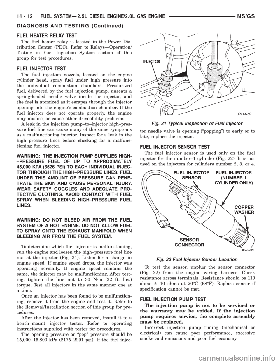
nut at the injector (Fig. 21). Listen for a change in
engine speed. If engine speed drops, the injector was
operating normally. If engine speed remains the
same, the injector may be malfunctioning. After test-
ing, tighten the line nut to 30 N´m (22 ft. lbs.)
torque. Test all injectors in the same manner one at
a time.
Once an injector has been found to be malfunction-
ing, remove it from the engine and test it. Refer to
the Removal/Installation section of this group for pro-
cedures.
After the injector has been removed, install it to a
bench±mount injector tester. Refer to operating
instructions supplied with tester for procedures.
The opening pressure or ªpopº pressure should be
15,000±15,800 kPa (2175±2291 psi). If the fuel injec-tor needle valve is opening (ªpoppingº) to early or to
late, replace the injector.
FUEL INJECTOR SENSOR TEST
The fuel injector sensor is used only on the fuel
injector for the number±1 cylinder (Fig. 22). It is not
used on the injectors for cylinders number 2, 3, or 4.
To test the sensor, unplug the sensor connector
(Fig. 22) from the engine wiring harness. Check
resistance across terminals. Resistance should be 110
ohms610 ohms at 20ÉC (68ÉF). Replace sensor if
specification cannot be met.
FUEL INJECTION PUMP TEST
The injection pump is not to be serviced or
the warranty may be voided. If the injection
pump requires service, the complete assembly
must be replaced.
Incorrect injection pump timing (mechanical or
electrical) can cause poor performance, excessive
smoke and emissions and poor fuel economy.
Fig. 21 Typical Inspection of Fuel Injector
Fig. 22 Fuel Injector Sensor Location
14 - 12 FUEL SYSTEMÐ2.5L DIESEL ENGINE/2.0L GAS ENGINENS/GS
DIAGNOSIS AND TESTING (Continued)
Page 1384 of 1938
REMOVAL AND INSTALLATION
ACCELERATOR PEDAL
CAUTION: Be careful not to damage or kink the
cable core wire (within the cable sheathing) while
servicing the accelerator pedal or throttle cable.
REMOVAL
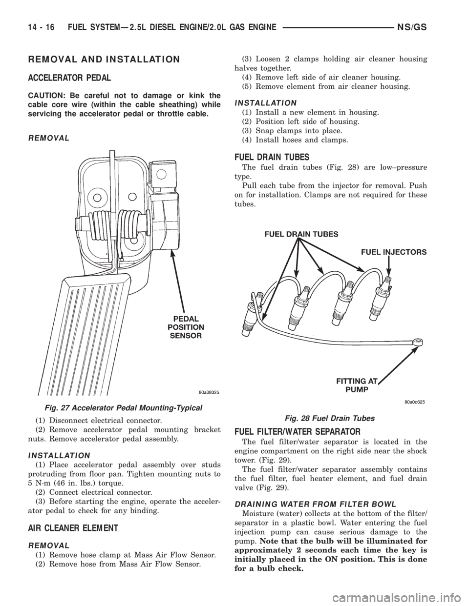
(1) Disconnect electrical connector.
(2) Remove accelerator pedal mounting bracket
nuts. Remove accelerator pedal assembly.
INSTALLATION
(1) Place accelerator pedal assembly over studs
protruding from floor pan. Tighten mounting nuts to
5 N´m (46 in. lbs.) torque.
(2) Connect electrical connector.
(3) Before starting the engine, operate the acceler-
ator pedal to check for any binding.
AIR CLEANER ELEMENT
REMOVAL
(1) Remove hose clamp at Mass Air Flow Sensor.
(2) Remove hose from Mass Air Flow Sensor.(3) Loosen 2 clamps holding air cleaner housing
halves together.
(4) Remove left side of air cleaner housing.
(5) Remove element from air cleaner housing.
INSTALLATION
(1) Install a new element in housing.
(2) Position left side of housing.
(3) Snap clamps into place.
(4) Install hoses and clamps.
FUEL DRAIN TUBES
The fuel drain tubes (Fig. 28) are low±pressure
type.
Pull each tube from the injector for removal. Push
on for installation. Clamps are not required for these
tubes.
FUEL FILTER/WATER SEPARATOR
The fuel filter/water separator is located in the
engine compartment on the right side near the shock
tower. (Fig. 29).
The fuel filter/water separator assembly contains
the fuel filter, fuel heater element, and fuel drain
valve (Fig. 29).
DRAINING WATER FROM FILTER BOWL
Moisture (water) collects at the bottom of the filter/
separator in a plastic bowl. Water entering the fuel
injection pump can cause serious damage to the
pump.Note that the bulb will be illuminated for
approximately 2 seconds each time the key is
initially placed in the ON position. This is done
for a bulb check.
Fig. 27 Accelerator Pedal Mounting-Typical
Fig. 28 Fuel Drain Tubes
14 - 16 FUEL SYSTEMÐ2.5L DIESEL ENGINE/2.0L GAS ENGINENS/GS
Page 1385 of 1938
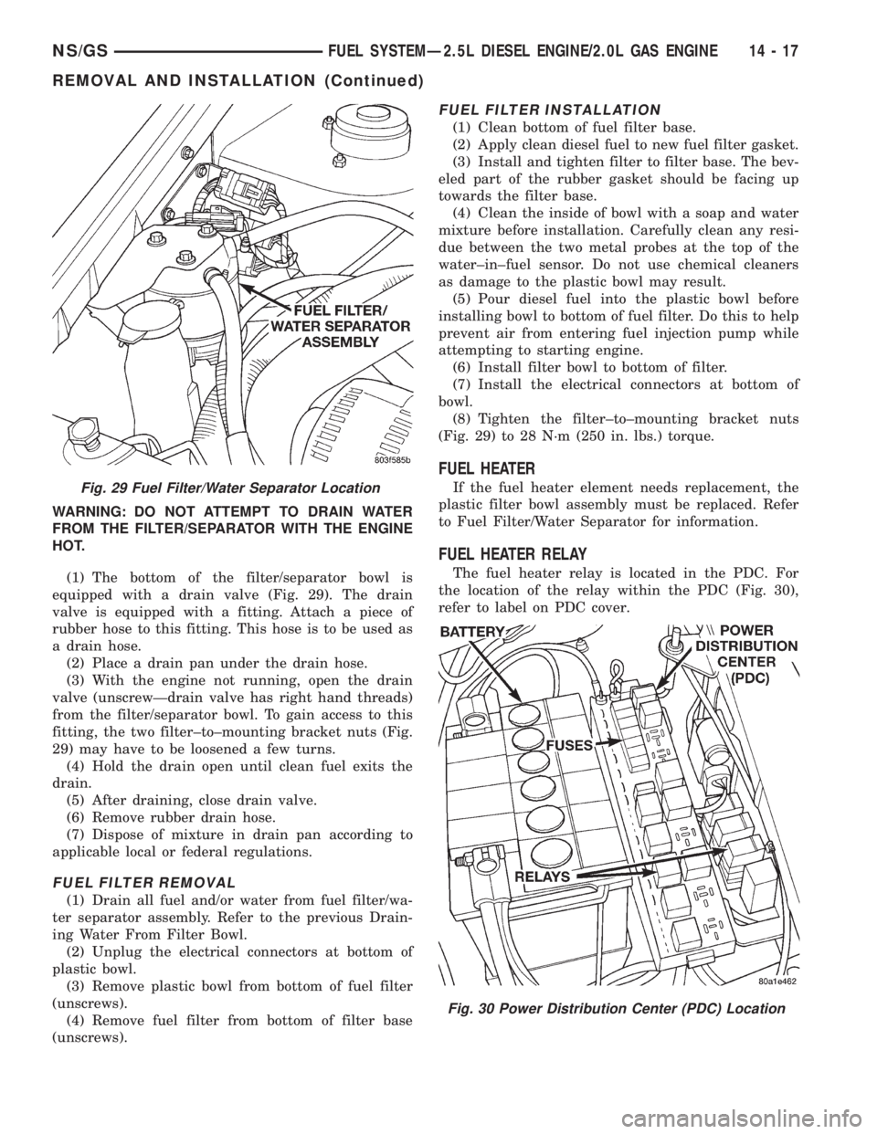
WARNING: DO NOT ATTEMPT TO DRAIN WATER
FROM THE FILTER/SEPARATOR WITH THE ENGINE
HOT.
(1) The bottom of the filter/separator bowl is
equipped with a drain valve (Fig. 29). The drain
valve is equipped with a fitting. Attach a piece of
rubber hose to this fitting. This hose is to be used as
a drain hose.
(2) Place a drain pan under the drain hose.
(3) With the engine not running, open the drain
valve (unscrewÐdrain valve has right hand threads)
from the filter/separator bowl. To gain access to this
fitting, the two filter±to±mounting bracket nuts (Fig.
29) may have to be loosened a few turns.
(4) Hold the drain open until clean fuel exits the
drain.
(5) After draining, close drain valve.
(6) Remove rubber drain hose.
(7) Dispose of mixture in drain pan according to
applicable local or federal regulations.
FUEL FILTER REMOVAL
(1) Drain all fuel and/or water from fuel filter/wa-
ter separator assembly. Refer to the previous Drain-
ing Water From Filter Bowl.
(2) Unplug the electrical connectors at bottom of
plastic bowl.
(3) Remove plastic bowl from bottom of fuel filter
(unscrews).
(4) Remove fuel filter from bottom of filter base
(unscrews).
FUEL FILTER INSTALLATION
(1) Clean bottom of fuel filter base.
(2) Apply clean diesel fuel to new fuel filter gasket.
(3) Install and tighten filter to filter base. The bev-
eled part of the rubber gasket should be facing up
towards the filter base.
(4) Clean the inside of bowl with a soap and water
mixture before installation. Carefully clean any resi-
due between the two metal probes at the top of the
water±in±fuel sensor. Do not use chemical cleaners
as damage to the plastic bowl may result.
(5) Pour diesel fuel into the plastic bowl before
installing bowl to bottom of fuel filter. Do this to help
prevent air from entering fuel injection pump while
attempting to starting engine.
(6) Install filter bowl to bottom of filter.
(7) Install the electrical connectors at bottom of
bowl.
(8) Tighten the filter±to±mounting bracket nuts
(Fig. 29) to 28 N´m (250 in. lbs.) torque.
FUEL HEATER
If the fuel heater element needs replacement, the
plastic filter bowl assembly must be replaced. Refer
to Fuel Filter/Water Separator for information.
FUEL HEATER RELAY
The fuel heater relay is located in the PDC. For
the location of the relay within the PDC (Fig. 30),
refer to label on PDC cover.
Fig. 29 Fuel Filter/Water Separator Location
Fig. 30 Power Distribution Center (PDC) Location
NS/GSFUEL SYSTEMÐ2.5L DIESEL ENGINE/2.0L GAS ENGINE 14 - 17
REMOVAL AND INSTALLATION (Continued)
Page 1386 of 1938
FUEL LEVEL SENSOR
REMOVAL
Remove fuel reservoir module. Refer to Fuel Reser-
voir Module in this section.
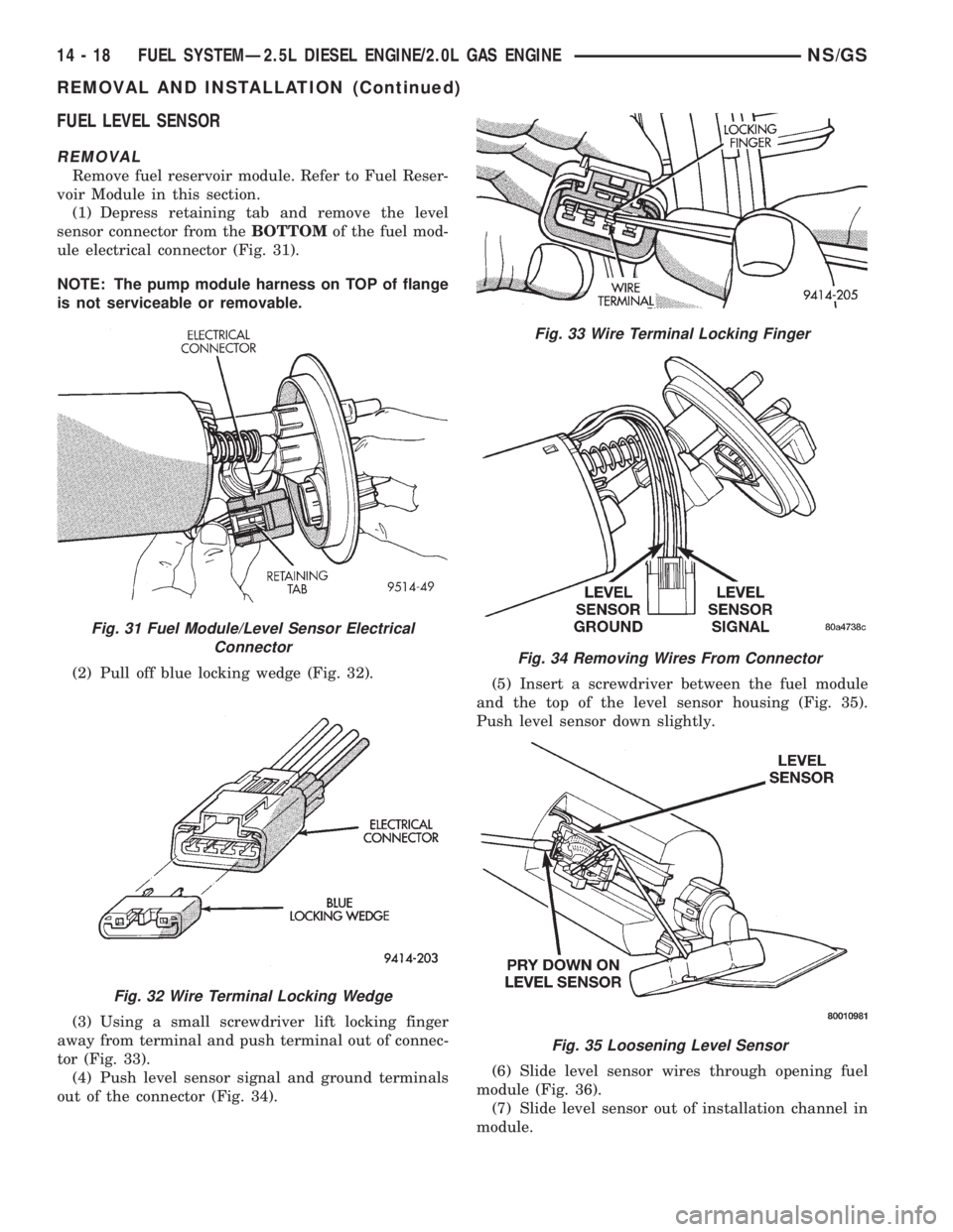
(1) Depress retaining tab and remove the level
sensor connector from theBOTTOMof the fuel mod-
ule electrical connector (Fig. 31).
NOTE: The pump module harness on TOP of flange
is not serviceable or removable.
(2) Pull off blue locking wedge (Fig. 32).
(3) Using a small screwdriver lift locking finger
away from terminal and push terminal out of connec-
tor (Fig. 33).
(4) Push level sensor signal and ground terminals
out of the connector (Fig. 34).(5) Insert a screwdriver between the fuel module
and the top of the level sensor housing (Fig. 35).
Push level sensor down slightly.
(6) Slide level sensor wires through opening fuel
module (Fig. 36).
(7) Slide level sensor out of installation channel in
module.
Fig. 31 Fuel Module/Level Sensor Electrical
Connector
Fig. 32 Wire Terminal Locking Wedge
Fig. 33 Wire Terminal Locking Finger
Fig. 34 Removing Wires From Connector
Fig. 35 Loosening Level Sensor
14 - 18 FUEL SYSTEMÐ2.5L DIESEL ENGINE/2.0L GAS ENGINENS/GS
REMOVAL AND INSTALLATION (Continued)