sensor CHRYSLER VOYAGER 1996 Service Manual
[x] Cancel search | Manufacturer: CHRYSLER, Model Year: 1996, Model line: VOYAGER, Model: CHRYSLER VOYAGER 1996Pages: 1938, PDF Size: 55.84 MB
Page 1404 of 1938
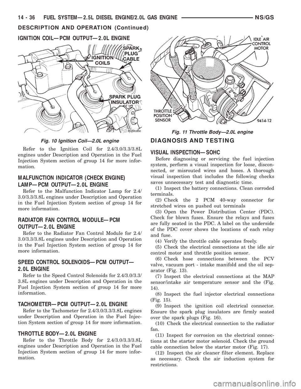
IGNITION COILÐPCM OUTPUTÐ2.0L ENGINE
Refer to the Ignition Coil for 2.4/3.0/3.3/3.8L
engines under Description and Operation in the Fuel
Injection System section of group 14 for more infor-
mation.
MALFUNCTION INDICATOR (CHECK ENGINE)
LAMPÐPCM OUTPUTÐ2.0L ENGINE
Refer to the Malfunction Indicator Lamp for 2.4/
3.0/3.3/3.8L engines under Description and Operation
in the Fuel Injection System section of group 14 for
more information.
RADIATOR FAN CONTROL MODULEÐPCM
OUTPUTÐ2.0L ENGINE
Refer to the Radiator Fan Control Module for 2.4/
3.0/3.3/3.8L engines under Description and Operation
in the Fuel Injection System section of group 14 for
more information.
SPEED CONTROL SOLENOIDSÐPCM OUTPUTÐ
2.0L ENGINE
Refer to the Speed Control Solenoids for 2.4/3.0/3.3/
3.8L engines under Description and Operation in the
Fuel Injection System section of group 14 for more
information.
TACHOMETERÐPCM OUTPUTÐ2.0L ENGINE
Refer to the Tachometer for 2.4/3.0/3.3/3.8L engines
under Description and Operation in the Fuel Injec-
tion System section of group 14 for more information.
THROTTLE BODYÐ2.0L ENGINE
Refer to the Throttle Body for 2.4/3.0/3.3/3.8L
engines under Description and Operation in the Fuel
Injection System section of group 14 for more infor-
mation.
DIAGNOSIS AND TESTING
VISUAL INSPECTIONÐSOHC
Before diagnosing or servicing the fuel injection
system, perform a visual inspection for loose, discon-
nected, or misrouted wires and hoses. A thorough
visual inspection that includes the following checks
saves unnecessary test and diagnostic time.
(1) Inspect the battery connections. Clean corroded
terminals.
(2) Check the 2 PCM 40-way connector for
stretched wires on pushed out terminals
(3) Open the Power Distribution Center (PDC).
Check for blown fuses. Ensure the relays and fuses
are fully seated in the PDC. A label on the underside
of the PDC cover shows the locations of each relay
and fuse.
(4) Verify the throttle cable operates freely.
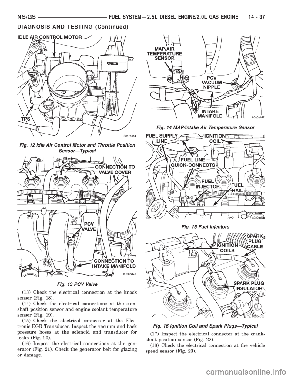
(5) Check the electrical connections at the idle air
control motor and throttle position sensor.
(6) Check hose connections between the PCV
valve, vacuum port - intake manifold and the oil sep-
arator (Fig. 13).
(7) Inspect the electrical connections at the MAP
sensor/intake air temperature sensor and the (Fig.
14).
(8) Inspect the fuel injector electrical connections
(Fig. 15).
(9) Inspect the ignition coil electrical connector.
Ensure the spark plug insulators are firmly seated
over the spark plugs (Fig. 16).
(10) Check the electrical connection to the radiator
fan.
(11) Inspect for corrosion on the electrical connec-
tions at the starter motor solenoid. Check the ground
cable connection below the starter motor (Fig. 17).
(12) Inspect the air cleaner filter element. Replace
as necessary. Check the air induction system for
restrictions.
Fig. 10 Ignition CoilÐ2.0L engine
Fig. 11 Throttle BodyÐ2.0L engine
14 - 36 FUEL SYSTEMÐ2.5L DIESEL ENGINE/2.0L GAS ENGINENS/GS
DESCRIPTION AND OPERATION (Continued)
Page 1405 of 1938
(13) Check the electrical connection at the knock
sensor (Fig. 18).
(14) Check the electrical connections at the cam-
shaft position sensor and engine coolant temperature
sensor (Fig. 19).
(15) Check the electrical connector at the Elec-
tronic EGR Transducer. Inspect the vacuum and back
pressure hoses at the solenoid and transducer for
leaks (Fig. 20).
(16) Inspect the electrical connections at the gen-
erator (Fig. 21). Check the generator belt for glazing
or damage.(17) Inspect the electrical connector at the crank-
shaft position sensor (Fig. 22).
(18) Check the electrical connection at the vehicle
speed sensor (Fig. 23).
Fig. 12 Idle Air Control Motor and Throttle Position
SensorÐTypical
Fig. 13 PCV Valve
Fig. 14 MAP/Intake Air Temperature Sensor
Fig. 15 Fuel Injectors
Fig. 16 Ignition Coil and Spark PlugsÐTypical
NS/GSFUEL SYSTEMÐ2.5L DIESEL ENGINE/2.0L GAS ENGINE 14 - 37
DIAGNOSIS AND TESTING (Continued)
Page 1406 of 1938
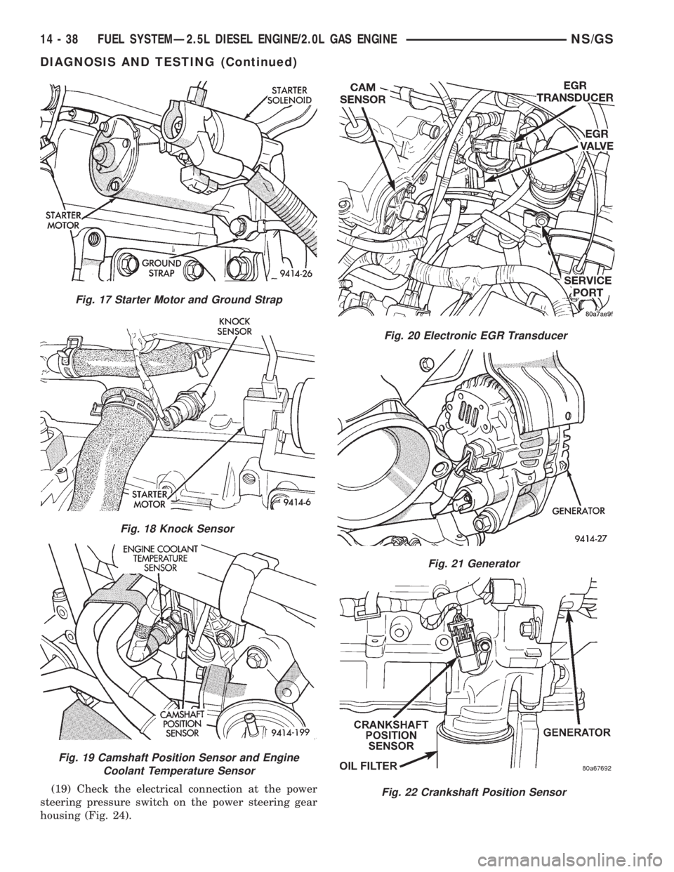
(19) Check the electrical connection at the power
steering pressure switch on the power steering gear
housing (Fig. 24).
Fig. 17 Starter Motor and Ground Strap
Fig. 18 Knock Sensor
Fig. 19 Camshaft Position Sensor and Engine
Coolant Temperature Sensor
Fig. 20 Electronic EGR Transducer
Fig. 21 Generator
Fig. 22 Crankshaft Position Sensor
14 - 38 FUEL SYSTEMÐ2.5L DIESEL ENGINE/2.0L GAS ENGINENS/GS
DIAGNOSIS AND TESTING (Continued)
Page 1407 of 1938
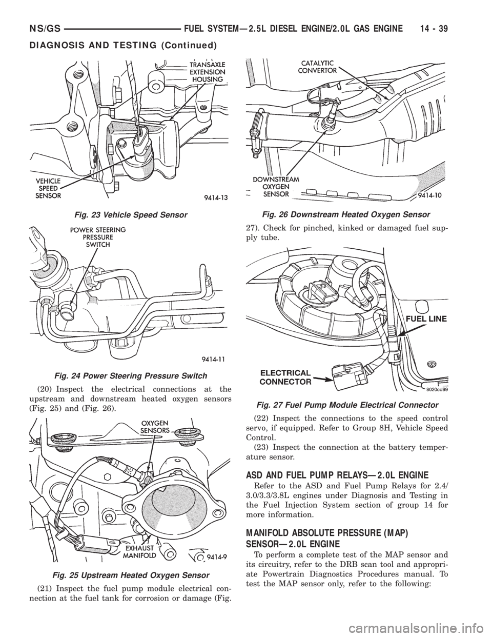
(20) Inspect the electrical connections at the
upstream and downstream heated oxygen sensors
(Fig. 25) and (Fig. 26).
(21) Inspect the fuel pump module electrical con-
nection at the fuel tank for corrosion or damage (Fig.27). Check for pinched, kinked or damaged fuel sup-
ply tube.
(22) Inspect the connections to the speed control
servo, if equipped. Refer to Group 8H, Vehicle Speed
Control.
(23) Inspect the connection at the battery temper-
ature sensor.
ASD AND FUEL PUMP RELAYSÐ2.0L ENGINE
Refer to the ASD and Fuel Pump Relays for 2.4/
3.0/3.3/3.8L engines under Diagnosis and Testing in
the Fuel Injection System section of group 14 for
more information.
MANIFOLD ABSOLUTE PRESSURE (MAP)
SENSORÐ2.0L ENGINE
To perform a complete test of the MAP sensor and
its circuitry, refer to the DRB scan tool and appropri-
ate Powertrain Diagnostics Procedures manual. To
test the MAP sensor only, refer to the following:
Fig. 23 Vehicle Speed Sensor
Fig. 24 Power Steering Pressure Switch
Fig. 25 Upstream Heated Oxygen Sensor
Fig. 26 Downstream Heated Oxygen Sensor
Fig. 27 Fuel Pump Module Electrical Connector
NS/GSFUEL SYSTEMÐ2.5L DIESEL ENGINE/2.0L GAS ENGINE 14 - 39
DIAGNOSIS AND TESTING (Continued)
Page 1408 of 1938
CAUTION: When testing the MAP sensor, be sure
that the harness wires are not damaged by the test
meter probes.
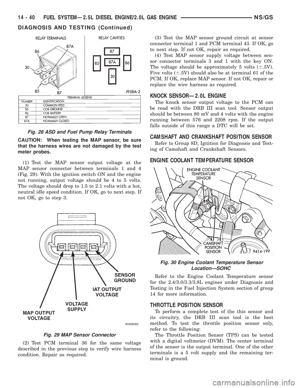
(1) Test the MAP sensor output voltage at the
MAP sensor connector between terminals 1 and 4
(Fig. 29). With the ignition switch ON and the engine
not running, output voltage should be 4 to 5 volts.
The voltage should drop to 1.5 to 2.1 volts with a hot,
neutral idle speed condition. If OK, go to next step. If
not OK, go to step 3.
(2) Test PCM terminal 36 for the same voltage
described in the previous step to verify wire harness
condition. Repair as required.(3) Test the MAP sensor ground circuit at sensor
connector terminal 1 and PCM terminal 43. If OK, go
to next step. If not OK, repair as required.
(4) Test MAP sensor supply voltage between sen-
sor connector terminals 3 and 1 with the key ON.
The voltage should be approximately 5 volts (6.5V).
Five volts (6.5V) should also be at terminal 61 of the
PCM. If OK, replace MAP sensor. If not OK, repair or
replace the wire harness as required.
KNOCK SENSORÐ2.0L ENGINE
The knock sensor output voltage to the PCM can
be read with the DRB III scan tool. Sensor output
should be between 80 mV and 4 volts with the engine
running between 576 and 2208 rpm. If the output
falls outside of this range a DTC will be set.
CAMSHAFT AND CRANKSHAFT POSITION SENSOR
Refer to Group 8D, Ignition for Diagnosis and Test-
ing of Camshaft and Crankshaft Sensors.
ENGINE COOLANT TEMPERATURE SENSOR
Refer to the Engine Coolant Temperature sensor
for the 2.4/3.0/3.3/3.8L engines under Diagnosis and
Testing in the Fuel Injection System section of group
14 for more information.
THROTTLE POSITION SENSOR
To perform a complete test of the this sensor and
its circuitry, the DRB III scan tool is the best
method. To test the throttle position sensor only,
refer to the following:
The Throttle Position Sensor (TPS) can be tested
with a digital voltmeter (DVM). The center terminal
of the sensor is the output terminal. One of the other
terminals is a 5 volt supply and the remaining ter-
minal is ground.
Fig. 28 ASD and Fuel Pump Relay Terminals
Fig. 29 MAP Sensor Connector
Fig. 30 Engine Coolant Temperature Sensor
LocationÐSOHC
14 - 40 FUEL SYSTEMÐ2.5L DIESEL ENGINE/2.0L GAS ENGINENS/GS
DIAGNOSIS AND TESTING (Continued)
Page 1409 of 1938

Connect the DVM between the center and sensor
ground terminal. Refer to Group 8W - Wiring Dia-
grams for correct pinout.
With the ignition switch in the ON position, check
the output voltage at the center terminal wire of the
connector. Check the output voltage at idle and at
Wide-Open-Throttle (WOT). At idle, TPS output volt-
age should be approximately 0.38 volts to 1.2 volts.
At wide open throttle, TPS output voltage should be
approximately 3.1 volts to 4.4 volts. The output volt-
age should gradually increase as the throttle plate
moves slowly from idle to WOT.
Check for spread terminals at the sensor and PCM
connections before replacing the TPS.
THROTTLE BODY MINIMUM AIR FLOW
(1) Turn ignition key to Off.
(2) D
isconnect the PCV valve hose from the intake
manifold nipple (Fig. 31). Cap the PCV vacuum nipple.
(3) Disconnect purge hose from the nipple on the
throttle body (Fig. 32).(4) Use a piece of hose to attach Air Metering Ori-
fice 6457 (0.125 in. orifice) to the purge nipple on the
throttle body (Fig. 33).
(5) Ensure that all accessories are off.
(6) Connect the DRB scan tool to the data link
connector inside the passenger compartment.
(7) Run engine in Park or Neutral until the cooling
fan has cycled on and off at least once (180ÉF).
(8) Using the DRB scan tool, access Minimum Air-
flow Idle Speed.
(9) The following will then occur:
²Idle air control motor will fully close
²Idle spark advance will become fixed
²PCM will go open loop enriched
²DRB scan tool displays engine RPM
(10) If idle RPM is within the range shown in the
Idle Specification chart, throttle body minimum air-
flow is set correctly.IDLE SPECIFICATION Ð2.0L ENGINE
Odometer Reading Idle RPM
Below 1000 Miles...............550±1300 RPM
Above 1000 Miles...............600±1300 RPM
(11) If idle RPM is above specifications, use the
DRB scan tool to check idle air control motor opera-
tion. If idle air control motor is OK, replace throttle
body. If idle air flow is below specification, shut off
the engine and clean the throttle body as follows:
WARNING: CLEAN THROTTLE BODY IN A WELL
VENTILATED AREA. WEAR RUBBER OR BUTYL
GLOVES, DO NOT LET MOPAR PARTS CLEANER
COME IN CONTACT WITH EYES OR SKIN. AVOID
INGESTING THE CLEANER. WASH THOROUGHLY
AFTER USING CLEANER.
Fig. 31 PCV Vacuum Nipple
Fig. 32 Purge Hose
Fig. 33 Orifice 6457 Attached to Purge Nipple
NS/GSFUEL SYSTEMÐ2.5L DIESEL ENGINE/2.0L GAS ENGINE 14 - 41
DIAGNOSIS AND TESTING (Continued)
Page 1410 of 1938

(a) Remove the throttle body from engine.
(b) While holding the throttle open, spray the
entire throttle body bore and the manifold side of
the throttle plate with Mopar Parts Cleaner.Only
use Mopar Parts Cleaner to clean the throttle
body.
(c) Using a soft scuff pad, clean the top and bot-
tom of throttle body bore and the edges and mani-
fold side of the throttle blade.The edges of the
throttle blade and portions of the throttle
bore that are closest to the throttle blade
when closed, must be free of deposits.
(d) Use compressed air to dry the throttle body.
(e) Inspect throttle body for foreign material.
(f) Install throttle body on manifold.
(g) Repeat steps 1 through 14. If the minimum
air flow is still not within specifications, the prob-
lem is not caused by the throttle body.
(12) Shut off engine.
(13) Remove Air Metering Orifice 6457. Install
purge hose.
(14) Remove cap from PCV valve. Connect hose to
PCV valve.
(15) Remove DRB scan tool.SPECIFICATIONS
TORQUE
DESCRIPTION TORQUE
Air Cleaner Wingnut.........1.5N´m(15in.lbs.)
Air Cleaner Mount. Stud-To-Thrott. Body . . 10 N´m
(90 in. lbs.)
Crankshaft Position Sensor Mounting Bolts . . 8 N´m
(70 in. lbs.)
Engine Coolant Temperature Sensor......18N´m
(165 in. lbs.)
IAC Motor-To-Throttle Body Bolts.........7N´m
(60 in. lbs.)
MAP/IAT Sensor.............2N´m(20in.lbs.)
MAP/IAT Sensor.............3N´m(30in.lbs.)
Oxygen Sensor..............28N´m(20ft.lbs.)
Powertrain Control Module
(PCM) Mounting Screws.....4N´m(35in.lbs.)
Throttle Cable Cover........4.5N´m(40in.lbs.).
Throttle Body Mounting Bolts...........23N´m
(200 in. lbs.)
Throttle Position Sensor Mounting Screws . . . 2 N´m
(20 in. lbs.)
Vehicle Speed Sensor Mounting Bolt......2.2N´m
(20 in. lbs.)
14 - 42 FUEL SYSTEMÐ2.5L DIESEL ENGINE/2.0L GAS ENGINENS/GS
DIAGNOSIS AND TESTING (Continued)
Page 1411 of 1938

FUEL INJECTION SYSTEMÐ2.5L DIESEL ENGINE
INDEX
page page
GENERAL INFORMATION
INTRODUCTION....................... 43
DESCRIPTION AND OPERATION
AIR CONDITIONING (A/C) CONTROLSÐ
PCM INPUTS........................ 47
AIR CONDITIONING RELAYÐPCM OUTPUT . . 48
BATTERY VOLTAGEÐPCM INPUT.......... 45
BOOST PRESSURE SENSOR............. 45
BRAKE SWITCHÐPCM INPUT............. 47
DATA LINK CONNECTORÐ
PCM INPUT AND OUTPUT.............. 47
DIESEL PCM RELAYÐPCM INPUT......... 48
ENGINE COOLANT GAUGEÐPCM OUTPUT . . 48
ENGINE COOLANT TEMPERATURE SENSORÐ
PCM INPUT......................... 46
ENGINE OIL PRESSURE GAUGEÐ
PCM OUTPUT........................ 48
ENGINE SPEED SENSORÐPCM INPUT..... 46
EXHAUST GAS RECIRCULATION (EGR)
SOLENOIDÐPCM OUTPUT............. 50
FIVE VOLT POWERÐPCM OUTPUT........ 48
FUEL INJECTOR SENSORÐGROUND...... 46
FUEL TIMING SOLENOIDÐPCM OUTPUT.... 48
GLOW PLUG LAMPÐPCM OUTPUT........ 48
GLOW PLUG RELAYÐPCM OUTPUT....... 49
GLOW PLUGS......................... 49
IGNITION CIRCUIT SENSEÐPCM INPUT.... 45
NEEDLE MOVEMENT OR INSTRUMENTED
FIRST INJECTORÐPCM INPUT.......... 45
POWER GROUND...................... 45
POWERTRAIN CONTROL MODULE (PCM) . . . 44
SENSOR RETURNÐPCM INPUT (ANALOG
GROUND)........................... 45SIGNAL GROUNDÐPCM INPUT........... 45
SPEED CONTROLÐPCM INPUTS.......... 48
SPEED CONTROLÐPCM OUTPUTS........ 48
START SIGNALÐPCM INPUT............. 45
TACHOMETERÐPCM OUTPUT............ 49
VEHICLE SPEED SENSORÐPCM INPUT.... 47
VEHICLE THEFT ALARM................. 45
DIAGNOSIS AND TESTING
BOOST PRESSURE SENSOR............. 53
DIAGNOSTIC TROUBLE CODES........... 53
DIESEL DIAGNOSTICS.................. 50
DIESEL PCM RELAY TEST............... 50
ENGINE COOLANT TEMPERATURE
SENSOR TEST....................... 50
ENGINE SPEED SENSOR TEST........... 50
GLOW PLUG RELAY TEST............... 51
GLOW PLUG TEST..................... 51
RELAYSÐOPERATION/TESTING........... 52
VEHICLE SPEED SENSOR TEST........... 53
REMOVAL AND INSTALLATION
A/C CLUTCH RELAY.................... 53
DIESEL PCM RELAY.................... 53
ENGINE COOLANT TEMPERATURE
SENSOR............................ 54
ENGINE SPEED SENSOR................ 53
GLOW PLUG RELAY.................... 55
GLOW PLUGS......................... 54
POWERTRAIN CONTROL MODULE (PCM) . . . 55
VEHICLE SPEED SENSOR............... 55
SPECIFICATIONS
GLOW PLUG CURRENT DRAW............ 56
TORQUE CHARTÐ2.5L DIESEL............ 57
GENERAL INFORMATION
INTRODUCTION
This section will cover components either regulated
or controlled by the Powertrain Control Module
(PCM). The fuel heater relay, fuel heater and fuel
gauge are not operated by the PCM. These compo-
nents are controlled by the ignition (key) switch. All
other fuel system electrical components necessary to
operate the engine are controlled or regulated by the
PCM. Refer to the following PCM description for
more information.
Certain fuel system component failures may cause
a no start, or prevent the engine from running. It is
important to know that the PCM has a featurewhere, if possible, it will ignore the failed sensor, set
a code related to the sensor, and operate the engine
in a ªLimp Homeº mode. When the PCM is operating
in a ªLimp Homeº mode, the Diesel Glow Plug lamp
on the instrument panel will be constantly illumi-
nated, and the engine will most likely have a notice-
able loss of performance. An example of this would be
an Accelerator Pedal Position Sensor failure, and in
that situation, the engine would run at a constant
1100 RPM, regardless of the actual position of the
pedal. This is the most extreme of the three ªLimp
Homeº modes.
In addition to indicating that the glow plugs are
hot enough to start combustion, the Glow Plug Lamp
is also used in the diagnosis of the PCM, and when
NS/GSFUEL SYSTEMÐ2.5L DIESEL ENGINE/2.0L GAS ENGINE 14 - 43
Page 1412 of 1938

illuminated constantly, it usually indicates a problem
has been detected somewhere within the fuel system.
The DRBIII scan tool is the best method for commu-
nicating with the PCM to diagnose faults within the
system.
DESCRIPTION AND OPERATION
POWERTRAIN CONTROL MODULE (PCM)
The Powertrain Control Module (PCM) is mounted
in the center consule to a bracket located in front of
the Air Bag Module (Fig. 1).
The PCM is a pre±programmed, dual micro±proces-
sor digital computer. It will either directly operate or
partially regulate the:
²Speed Control
²Speed Control LED lamp
²Fuel Timing Solenoid
²Glow Plug Relay
²Glow Plugs
²EGR Solenoid
²Glow Plug Lamp
²Diesel PCM Relay
²Air Conditioning Operation
²Tachometer
²Exhaust Gas Recirculation (EGR) Solenoid
The PCM can adapt its programming to meet
changing operating conditions.
The PCM receives input signals from various
switches and sensors. Based on these inputs, the
PCM regulates various engine and vehicle operationsthrough different system components. These compo-
nents are referred to asPCM Outputs.The sensors
and switches that provide inputs to the PCM are con-
sideredPCM Inputs.
PCM Inputs are:
²Air Conditioning Selection
²Theft Alarm
²Clutch Switch
²Diesel PCM Relay
²ISO-Protocol
²Control Sleeve
²Fuel Temperature
²Boost Pressure Sensor
²Accelerator Pedal Sensor
²EGR
²A/C Pressure
²Engine Coolant Temperature Sensor
²Low Idle Position Switch
²5 Volt Supply
²Vehicle Speed Sensor
²Sensor Return
²Glow Plug
²Engine Speed Sensor (rpm)
²Fuel Injector #1 Sensor
²Starter Signal
²Brake Switch
²Speed Control Switch Position
²Power Ground
²Signal Ground
²Ignition (key) Switch Sense
²Battery Voltage
²SCI Receive (DRB scan tool connection)
PCM Outputs:
After inputs are received by the PCM, certain sen-
sors, switches and components are controlled or reg-
ulated by the PCM. These are consideredPCM
Outputs.These outputs are for:
²A/C Clutch Relay (for A/C clutch operation)
²Speed Control LED
²Data Link Connectors (for DRB scan tool)
²Diesel PCM Relay
²Diesel PCM Sense
²Accelarator Pedal
²5 Volts Supply
²Glow Plug Relay
²Fan Relay
²Fuel Quantity
²Fuel Timing Solenoid
²Fuel Shut-Off Solenoid
²Engine Speed Sensor
²Glow Plug Lamp (malfunction indicator lamp)
²Exhaust Gas Recirculation (EGR) Solenoid
²Glow Plug Relay
²Tachometer
²SCI transmit (DRB scan tool connection)
Fig. 1 PCM Location
14 - 44 FUEL SYSTEMÐ2.5L DIESEL ENGINE/2.0L GAS ENGINENS/GS
GENERAL INFORMATION (Continued)
Page 1413 of 1938

BOOST PRESSURE SENSOR
The Boost Pressure Sensor is mounted to the top of
the intake manifold. (Fig. 2) It is a sensor that mea-
sures both manifold vacuum and turbo boost, and it
also contains an integrated intake air temperature
sensor. The Boost Pressure Sensor takes the place of
the Mass Air Flow (MAF). In the Intake Air Temper-
ature Sensor component, there is a ceramic element
that changes its resistance based on temperature.
The ceramic element is part of an electronic circuit
connected to the PCM, and has a voltage applied to
it. The ceramic element is exposed to the air inside
the intake. This air has a cooling effect on the
ceramic element, and its resistance changes. This
causes the voltage flowing through the intake air
temperature circuit to vary. The voltage signal pro-
duced by the Intake Air Temperature Sensor changes
inversely to the temperature, and is measured by the
PCM. As a general rule, when the temperature of the
air in the intake is high, the voltage signal produced
by the Intake Air Temperature Sensor is low. The
component of the Boost Pressure Sensor that mea-
sures manifold vacuum and turbo boost produces a
voltage signal that is proportional to the pressure in
the inake manifold. When the intake manifold pres-
sure is low, the voltage is low, and when the pressure
is high, the voltage is high. The PCM uses the volt-
age signals from the Boost Pressure Sensor, and the
Intake Air Temperature Sensor to determine the
amount of air flowing through the intake manifold.
VEHICLE THEFT ALARM
The PCM can learn if the vehicle has a Vehicle
Theft Alarm (VTA) system. Once it detects the vehi-
cle having VTA,the controller can ONLY BE
USED ON VEHICLES WITH VTA.If the PCM is put it on a vehicle without VTA the
Glow Plug Lamp will start to blink and the vehicle
will not start.
The PCM cannot be flashed to remove the VTA.
BATTERY VOLTAGEÐPCM INPUT
The battery voltage input provides power to the
PCM. It also informs the PCM what voltage level is
being supplied by the generator once the vehicle is
running.
The battery input also provides the voltage that is
needed to keep the PCM memory alive. The memory
stores Diagnostic Trouble Code (DTC) messages.
Trouble codes will still be stored even if the battary
voltage is lost.
SENSOR RETURNÐPCM INPUT (ANALOG
GROUND)
Sensor Return provides a low noise Analog ground
reference for all system sensors.
SIGNAL GROUNDÐPCM INPUT
Signal ground provides a low noise ground to the
data link connector.
IGNITION CIRCUIT SENSEÐPCM INPUT
The ignition circuit sense input signals the PCM
that the ignition (key) switch has been turned to the
ON position. This signal initiates the glow plug con-
trol routine to begin the ªpre±heatº cycle.
START SIGNALÐPCM INPUT
This input tells the PCM that the engine starter is
being operated. This in turn will start the glow plug
ªpost±heatº cycle.
POWER GROUND
Provides a common ground for power devices (sole-
noid and relay devices).
NEEDLE MOVEMENT OR INSTRUMENTED FIRST
INJECTORÐPCM INPUT
This input from the PCM supplies a constant 30
mA electrical current source for the first injector sen-
sor. It will vary the voltage to this sensor when it
senses a mechanical movement within the injector
needle (pintle) of the number±1 cylinder fuel injector.
When this voltage has been determined by the PCM,
it will then control an output to the fuel timing sole-
noid (the fuel timing solenoid is located on the fuel
injection pump). Also refer to Fuel Injection Pump for
additional information.
The first injector sensor is a magnetic (inductive)
type.
Fig. 2 Boost Pressure Sensor Location
NS/GSFUEL SYSTEMÐ2.5L DIESEL ENGINE/2.0L GAS ENGINE 14 - 45
DESCRIPTION AND OPERATION (Continued)