sensor CHRYSLER VOYAGER 1996 Service Manual
[x] Cancel search | Manufacturer: CHRYSLER, Model Year: 1996, Model line: VOYAGER, Model: CHRYSLER VOYAGER 1996Pages: 1938, PDF Size: 55.84 MB
Page 1437 of 1938
REMOVAL AND INSTALLATION
2.4 LITER POWER STEERING PUMP
REMOVE
WARNING: POWER STEERING OIL, ENGINE COM-
PONENTS AND THE EXHAUST SYSTEM MAY BE
EXTREMELY HOT IF ENGINE HAS BEEN RUNNING.
DO NOT START ENGINE WITH ANY LOOSE OR DIS-
CONNECTED HOSES. DO NOT ALLOW HOSES TO
TOUCH HOT EXHAUST MANIFOLD OR CATALYST.
(1) Remove cap from power steering fluid reser-
voir.
(2) Using a siphon pump, remove as much power
steering fluid as possible from the power steering
fluid reservoir.
(3) Remove the (-) negative battery cable from the
battery and isolate cable.
(4) Remove the drive belt from the power steering
pump pulley. See Cooling, Group 7 for detailed
removal procedure.
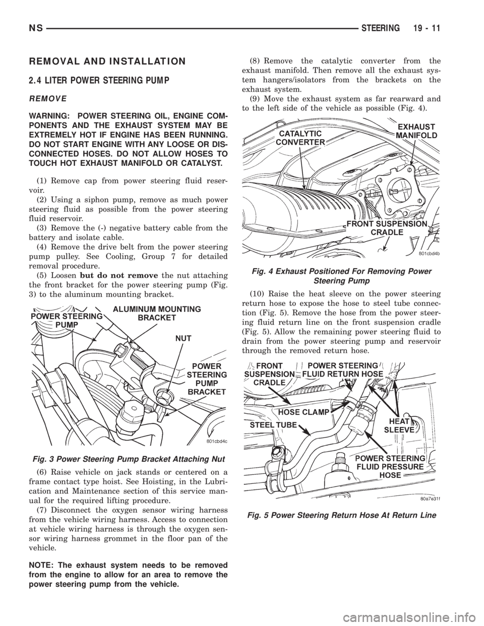
(5) Loosenbut do not removethe nut attaching
the front bracket for the power steering pump (Fig.
3) to the aluminum mounting bracket.
(6) Raise vehicle on jack stands or centered on a
frame contact type hoist. See Hoisting, in the Lubri-
cation and Maintenance section of this service man-
ual for the required lifting procedure.
(7) Disconnect the oxygen sensor wiring harness
from the vehicle wiring harness. Access to connection
at vehicle wiring harness is through the oxygen sen-
sor wiring harness grommet in the floor pan of the
vehicle.
NOTE: The exhaust system needs to be removed
from the engine to allow for an area to remove the
power steering pump from the vehicle.(8) Remove the catalytic converter from the
exhaust manifold. Then remove all the exhaust sys-
tem hangers/isolators from the brackets on the
exhaust system.
(9) Move the exhaust system as far rearward and
to the left side of the vehicle as possible (Fig. 4).
(10) Raise the heat sleeve on the power steering
return hose to expose the hose to steel tube connec-
tion (Fig. 5). Remove the hose from the power steer-
ing fluid return line on the front suspension cradle
(Fig. 5). Allow the remaining power steering fluid to
drain from the power steering pump and reservoir
through the removed return hose.
Fig. 3 Power Steering Pump Bracket Attaching Nut
Fig. 4 Exhaust Positioned For Removing Power
Steering Pump
Fig. 5 Power Steering Return Hose At Return Line
NSSTEERING 19 - 11
Page 1439 of 1938
(18) Remove the 3 previously loosened bolts
attaching the front bracket to the power steering
pump and separate the power steering pump from
the front bracket prior to removing the pump from
the vehicle.
(19) The power steering pump is removed from the
vehicle by pulling it out through the exhaust tunnel
area in the floor pan of the vehicle.
INSTALL
(1) Install power steering pump back in vehicle
using the reverse order of its removal through the
exhaust tunnel are of the vehicle.
(2) Install the power steering pump on its cast
mounting bracket and loosely install nut to hold
pump in place (Fig. 9).
(3) Install the front bracket on the power steering
pump and loosely install the 3 mounting bolts (Fig.
10). Then install the nut and bolt attaching the front
bracket to the cast bracket (Fig. 10).
(4) Tighten the 3 power steering pump mounting
bolts (Fig. 10) to a torque of 54 N´m (40 ft. lbs.).
NOTE: Before installing power steering fluid pres-
sure hose on power steering pump, inspect the
O-ring on the pressure hose for damage and
replace if necessary.
(5) Install the power steering fluid pressure line
onto the output fitting of the power steering pump
(Fig. 8). Tighten the pressure line to pump fitting
tube nut to a torque of 31 N´m (275 in. lbs.).
(6) Install the power steering fluid, low pressure
return hose on the power steering pump low pressure
fitting (Fig. 8).Be sure hose clamps are properly
reinstalled.
(7) Install the power steering fluid supply hose
from the power steering fluid reservoir, on the power
steering pump fluid fitting (Fig. 7).Be sure hose is
clear of accessory drive belts all hose clamps
are properly reinstalled.
(8) Install the power steering pump drive belt on
pulley. See Cooling, Group 7 for detailed installation
procedure.
(9) Install the accessory drive splash shield (Fig.
6).
(10) Install the power steering fluid return hose on
the steel tube at the front suspension cradle (Fig. 5).
(11) Install a screw type hose clamp on the power
steering hose to steel tube connection.Be sure hose
clamps are properly reinstalled.Tighten the screw
clamp to a torque of 2 N´m (18 in. lbs.).
CAUTION: The protective heat shield sleeves must
cover the entire rubber hose and hose to tube con-
nection portion of both the power steering fluid
pressure and return hoses (Fig. 5). This is requiredto prevent the overheating of the power steering
hoses.
(12) When used, properly position the protective
heat sleeves on the power steering hoses (Fig. 5).
Then, tie strap the heat sleeves to the power steering
hoses to keep them in their proper position.
(13) Install the exhaust pipe on the exhaust man-
ifold. Install all exhaust system hangers/isolators on
the exhaust system brackets.
(14) Connect the oxygen sensor wiring harness to
the vehicle wiring harness. Install wiring harness
grommet in the floor pan of the vehicle.
(15) Lower vehicle.
(16) Adjust the power steering pump drive belt.
See Cooling, Group 7 for detailed adjustment proce-
dure.
(17) Tighten the top nut and bottom bolt on the
power steering pump front mounting bracket (Fig. 3)
to a torque of 54 N´m (40 ft. lbs.).
CAUTION: Do not use automatic transmission fluid
in power steering system. Only use MoparT, Power
Steering Fluid, or equivalent.
(18) Fill the remote power steering pump fluid res-
ervoir to correct fluid level.
(19) Install cap on power steering fluid reservoir.
(20) Connect the negative battery cable on the
negative battery post.
(21) Start engine and turn steering wheel several
times from stop to stop to bleed air from fluid in sys-
tem. Stop engine, check fluid level, and inspect sys-
tem for leaks. See Checking Fluid Level.
3.0 LITER POWER STEERING PUMP
REMOVE
WARNING: POWER STEERING OIL, ENGINE COM-
PONENTS AND THE EXHAUST SYSTEM MAY BE
EXTREMELY HOT IF ENGINE HAS BEEN RUNNING.
DO NOT START ENGINE WITH ANY LOOSE OR DIS-
CONNECTED HOSES. DO NOT ALLOW HOSES TO
TOUCH HOT EXHAUST MANIFOLD OR CATALYST.
(1) Remove the (-) negative battery cable from the
battery and isolate cable.
(2) Remove cap from power steering fluid reser-
voir.
(3) Using a siphon pump, remove as much power
steering fluid as possible from the power steering
fluid reservoir.
NSSTEERING 19 - 13
REMOVAL AND INSTALLATION (Continued)
Page 1440 of 1938
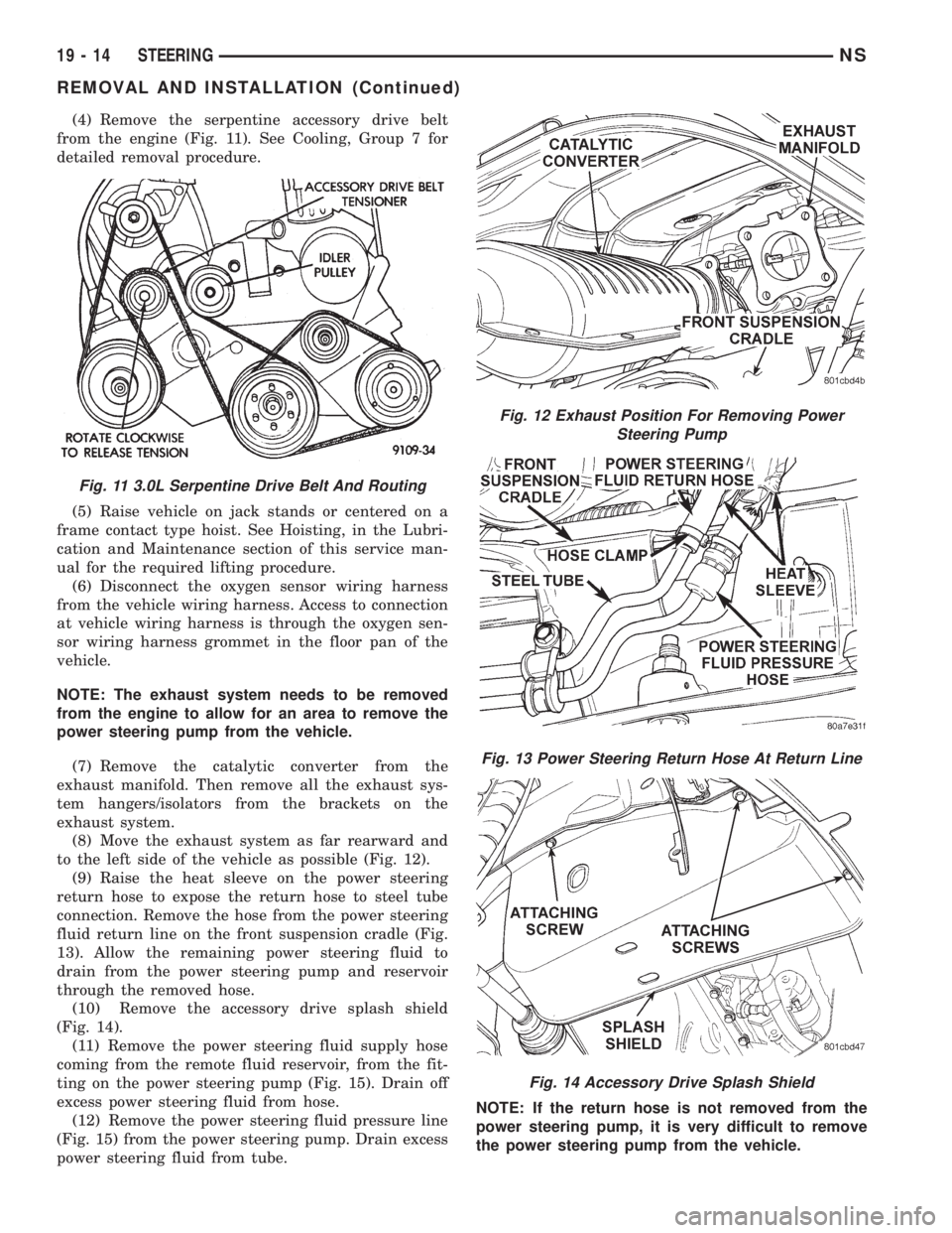
(4) Remove the serpentine accessory drive belt
from the engine (Fig. 11). See Cooling, Group 7 for
detailed removal procedure.
(5) Raise vehicle on jack stands or centered on a
frame contact type hoist. See Hoisting, in the Lubri-
cation and Maintenance section of this service man-
ual for the required lifting procedure.
(6) Disconnect the oxygen sensor wiring harness
from the vehicle wiring harness. Access to connection
at vehicle wiring harness is through the oxygen sen-
sor wiring harness grommet in the floor pan of the
vehicle.
NOTE: The exhaust system needs to be removed
from the engine to allow for an area to remove the
power steering pump from the vehicle.
(7) Remove the catalytic converter from the
exhaust manifold. Then remove all the exhaust sys-
tem hangers/isolators from the brackets on the
exhaust system.
(8) Move the exhaust system as far rearward and
to the left side of the vehicle as possible (Fig. 12).
(9) Raise the heat sleeve on the power steering
return hose to expose the return hose to steel tube
connection. Remove the hose from the power steering
fluid return line on the front suspension cradle (Fig.
13). Allow the remaining power steering fluid to
drain from the power steering pump and reservoir
through the removed hose.
(10) Remove the accessory drive splash shield
(Fig. 14).
(11) Remove the power steering fluid supply hose
coming from the remote fluid reservoir, from the fit-
ting on the power steering pump (Fig. 15). Drain off
excess power steering fluid from hose.
(12) Remove the power steering fluid pressure line
(Fig. 15) from the power steering pump. Drain excess
power steering fluid from tube.NOTE: If the return hose is not removed from the
power steering pump, it is very difficult to remove
the power steering pump from the vehicle.
Fig. 11 3.0L Serpentine Drive Belt And Routing
Fig. 12 Exhaust Position For Removing Power
Steering Pump
Fig. 13 Power Steering Return Hose At Return Line
Fig. 14 Accessory Drive Splash Shield
19 - 14 STEERINGNS
REMOVAL AND INSTALLATION (Continued)
Page 1441 of 1938
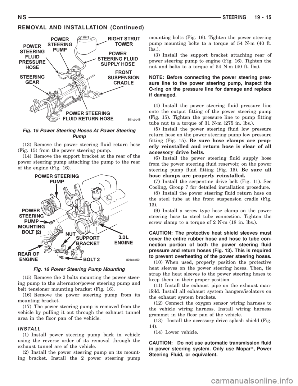
(13) Remove the power steering fluid return hose
(Fig. 15) from the power steering pump.
(14) Remove the support bracket at the rear of the
power steering pump attaching the pump to the rear
of the engine (Fig. 16).
(15) Remove the 2 bolts mounting the power steer-
ing pump to the alternator/power steering pump and
belt tensioner mounting bracket (Fig. 16).
(16) Remove the power steering pump from its
mounting bracket.
(17) The power steering pump is removed from the
vehicle by pulling it out through the exhaust tunnel
area in the floor pan of the vehicle.
INSTALL
(1) Install power steering pump back in vehicle
using the reverse order of its removal through the
exhaust tunnel are of the vehicle.
(2) Install the power steering pump on its mount-
ing bracket. Install the 2 power steering pumpmounting bolts (Fig. 16). Tighten the power steering
pump mounting bolts to a torque of 54 N´m (40 ft.
lbs.).
(3) Install the support bracket attaching rear of
power steering pump to engine (Fig. 16). Tighten the
nut and bolts to a torque of 54 N´m (40 ft. lbs).
NOTE: Before connecting the power steering pres-
sure line to the power steering pump, inspect the
O-ring on the pressure line for damage and replace
if damaged.
(4) Install the power steering fluid pressure line
onto the output fitting of the power steering pump
(Fig. 15). Tighten the pressure line to pump fitting
tube nut to a torque of 31 N´m (275 in. lbs.).
(5) Install the power steering fluid low pressure
return hose on the power steering pump low pressure
fitting (Fig. 15).Be sure hose clamps are prop-
erly reinstalled and return hose is clear of all
accessory drive belts.
(6) Install the power steering fluid supply hose
from the power steering fluid reservoir, on the power
steering pump fluid fitting (Fig. 15).Be sure all
hose clamps are properly reinstalled.
(7) Install the serpentine drive belt (Fig. 11). See
Cooling, Group 7 for detailed installation procedure.
(8) Install the power steering fluid return hose on
the steel tube at the front suspension cradle (Fig.
13).
(9) Install a screw type hose clamp on the power
steering hose to steel tube connection. Tighten the
screw clamp to a torque of 2 N´m (18 in. lbs.).
CAUTION: The protective heat shield sleeves must
cover the entire rubber hose and hose to tube con-
nection portion of both the power steering fluid
pressure and return hoses (Fig. 13). This is required
to prevent overheating of the power steering hoses.
(10) When used, properly position the protective
heat sleeves on the power steering hoses. Then, tie
strap the heat sleeves to the power steering hoses to
keep them in their proper position.
(11) Install the exhaust pipe on the exhaust man-
ifold. Install all exhaust system hangers/isolators on
the exhaust system brackets.
(12) Connect the oxygen sensor wiring harness to
the vehicle wiring harness. Install wiring harness
grommet in the floor pan of the vehicle.
(13) Install the accessory drive splash shield (Fig.
14).
(14) Lower vehicle.
CAUTION: Do not use automatic transmission fluid
in power steering system. Only use MoparT, Power
Steering Fluid, or equivalent.
Fig. 15 Power Steering Hoses At Power Steering
Pump
Fig. 16 Power Steering Pump Mounting
NSSTEERING 19 - 15
REMOVAL AND INSTALLATION (Continued)
Page 1442 of 1938
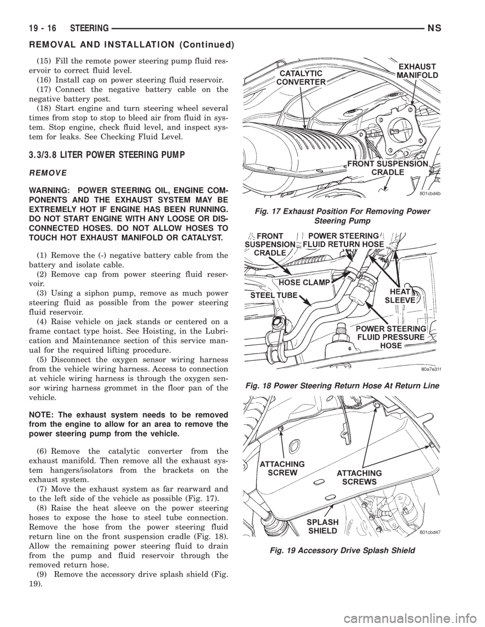
(15) Fill the remote power steering pump fluid res-
ervoir to correct fluid level.
(16) Install cap on power steering fluid reservoir.
(17) Connect the negative battery cable on the
negative battery post.
(18) Start engine and turn steering wheel several
times from stop to stop to bleed air from fluid in sys-
tem. Stop engine, check fluid level, and inspect sys-
tem for leaks. See Checking Fluid Level.
3.3/3.8 LITER POWER STEERING PUMP
REMOVE
WARNING: POWER STEERING OIL, ENGINE COM-
PONENTS AND THE EXHAUST SYSTEM MAY BE
EXTREMELY HOT IF ENGINE HAS BEEN RUNNING.
DO NOT START ENGINE WITH ANY LOOSE OR DIS-
CONNECTED HOSES. DO NOT ALLOW HOSES TO
TOUCH HOT EXHAUST MANIFOLD OR CATALYST.
(1) Remove the (-) negative battery cable from the
battery and isolate cable.
(2) Remove cap from power steering fluid reser-
voir.
(3) Using a siphon pump, remove as much power
steering fluid as possible from the power steering
fluid reservoir.
(4) Raise vehicle on jack stands or centered on a
frame contact type hoist. See Hoisting, in the Lubri-
cation and Maintenance section of this service man-
ual for the required lifting procedure.
(5) Disconnect the oxygen sensor wiring harness
from the vehicle wiring harness. Access to connection
at vehicle wiring harness is through the oxygen sen-
sor wiring harness grommet in the floor pan of the
vehicle.
NOTE: The exhaust system needs to be removed
from the engine to allow for an area to remove the
power steering pump from the vehicle.
(6) Remove the catalytic converter from the
exhaust manifold. Then remove all the exhaust sys-
tem hangers/isolators from the brackets on the
exhaust system.
(7) Move the exhaust system as far rearward and
to the left side of the vehicle as possible (Fig. 17).
(8) Raise the heat sleeve on the power steering
hoses to expose the hose to steel tube connection.
Remove the hose from the power steering fluid
return line on the front suspension cradle (Fig. 18).
Allow the remaining power steering fluid to drain
from the pump and fluid reservoir through the
removed return hose.
(9) Remove the accessory drive splash shield (Fig.
19).
Fig. 17 Exhaust Position For Removing Power
Steering Pump
Fig. 18 Power Steering Return Hose At Return Line
Fig. 19 Accessory Drive Splash Shield
19 - 16 STEERINGNS
REMOVAL AND INSTALLATION (Continued)
Page 1444 of 1938
NOTE: Before installing power steering pressure
hose on power steering pump, inspect the O-ring
on the power steering pressure hose for damage
and replace if required.
(4) Install the power steering fluid pressure line
onto the output fitting of the power steering pump
(Fig. 21). Tighten the pressure line to pump fitting
tube nut to a torque of 31 N´m (275 in. lbs.).
(5) Install the power steering fluid, low pressure
return hose on the power steering pump low pressure
fitting (Fig. 21).Be sure hose clamps are prop-
erly reinstalled.
(6) Install the power steering fluid supply hose
from the power steering fluid reservoir, on the power
steering pump fluid fitting (Fig. 21).Be sure hose is
clear of accessory drive belts and all hose
clamps are properly reinstalled.
(7) Install the serpentine drive belt (Fig. 20). See
Cooling, Group 7 for detailed installation procedure.
(8) Install the power steering fluid return hose on
the steel tube at the front suspension cradle (Fig.
18).
(9) Install a screw type hose clamp on the power
steering hose to steel tube connection.Be sure hose
clamps are properly reinstalled.Tighten the screw
clamp to a torque of 2 N´m (18 in. lbs.).
CAUTION: The protective heat shield sleeves must
cover the entire rubber hose and hose to tube con-
nection portion of both the power steering fluid
pressure and return hoses (Fig. 18). This is required
to keep the power steering hoses from becoming
overheated.
(10) When used, properly position the protective
heat sleeves on the power steering hoses (Fig. 18).
Then, tie strap the heat sleeves to the power steering
hoses to keep them in their proper position.
(11) Install the exhaust pipe on the exhaust man-
ifold. Install all exhaust system hangers/isolators on
the exhaust system brackets.
(12) Connect the oxygen sensor wiring harness to
the vehicle wiring harness. Install wiring harness
grommet in the floor pan of the vehicle.
(13) Install the accessory drive splash shield (Fig.
19).
(14) Lower vehicle.
CAUTION: Do not use automatic transmission fluid
in power steering system. Only use MoparT, Power
Steering Fluid, or equivalent.
(15) Fill the remote power steering pump fluid res-
ervoir to correct fluid level.
(16) Install cap on power steering fluid reservoir.(17) Connect the negative battery cable on the
negative battery post.
(18) Start engine and turn steering wheel several
times from stop to stop to bleed air from fluid in sys-
tem. Stop engine, check fluid level, and inspect sys-
tem for leaks. See Checking Fluid Level.
POWER STEERING FLUID RESERVOIR TO PUMP
SUPPLY HOSE
REMOVE
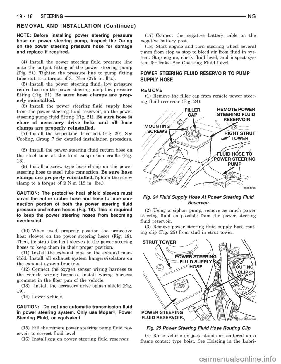
(1) Remove the filler cap from remote power steer-
ing fluid reservoir (Fig. 24).
(2) Using a siphon pump, remove as much power
steering fluid as possible from the power steering
fluid reservoir.
(3) Remove power steering fluid supply hose rout-
ing clip (Fig. 25) from stud in strut tower.
(4) Raise vehicle on jack stands or centered on a
frame contact type hoist. See Hoisting in the Lubri-
Fig. 24 Fluid Supply Hose At Power Steering Fluid
Reservoir
Fig. 25 Power Steering Fluid Hose Routing Clip
19 - 18 STEERINGNS
REMOVAL AND INSTALLATION (Continued)
Page 1475 of 1938
TRANSAXLE AND POWER TRANSFER UNIT
CONTENTS
page page
31TH AUTOMATIC TRANSAXLE.............. 1
41TE AUTOMATIC TRANSAXLE............. 71POWER TRANSFER UNIT................. 165
31TH AUTOMATIC TRANSAXLE
INDEX
page page
GENERAL INFORMATION
31TH TRANSAXLE........................ 2
FLUID LEVEL AND CONDITION.............. 2
SELECTION OF LUBRICANT................ 3
SPECIAL ADDITIVES...................... 3
DESCRIPTION AND OPERATION
CLUTCHES, BAND SERVOS, AND
ACCUMULATOR
...................... 3
FLOW CONTROL VALVES.................. 3
GEARSHIFT AND PARKING LOCK CONTROLS . . 4
GOVERNOR............................. 4
HYDRAULIC CONTROL SYSTEM............. 3
PRESSURE REGULATING VALVES........... 3
PRESSURE SUPPLY SYSTEM............... 3
TORQUE CONVERTER CLUTCH SOLENOID
WIRING CONNECTOR................... 4
TORQUE CONVERTER CLUTCH............. 3
DIAGNOSIS AND TESTING
CLUTCH AND SERVO AIR PRESSURE TESTS . 15
FLUID LEAKAGE-TRANSAXLE TORQUE
CONVERTER HOUSING AREA............ 15
HYDRAULIC PRESSURE TESTS............ 13
ROAD TEST............................. 4
THREE SPEED TRANSAXLE DIAGNOSIS AND
TESTS............................... 4
SERVICE PROCEDURES
ALUMINUM THREAD REPAIR.............. 18
FLUID AND FILTER CHANGE............... 16
FLUID DRAIN AND REFILL................. 18
FLUSHING COOLERS AND TUBES.......... 18
OIL PUMP VOLUME CHECK............... 19
REMOVAL AND INSTALLATION
FRONT PUMP OIL SEAL.................. 21
PARK/NEUTRAL STARTING AND BACK-UP
LAMP SWITCH........................ 19
TRANSAXLE AND TORQUE CONVERTER
REMOVAL............................ 20
VEHICLE SPEED SENSOR PINION GEAR..... 19DISASSEMBLY AND ASSEMBLY
ACCUMULATOR-RECONDITION............ 36
DIFFERENTIAL REPAIR................... 46
FRONT CLUTCH-RECONDITION............ 32
FRONT PLANETARY & ANNULUS GEAR-
RECONDITION........................ 35
KICKDOWN SERVO (CONTROLLED LOAD)-
RECONDITION........................ 37
LOW/REVERSE (REAR)
SERVO-RECONDITION.................. 36
OIL PUMP-RECONDITION................. 31
OUTPUT SHAFT REPAIR.................. 43
PARKING PAWL......................... 42
REAR CLUTCH-RECONDITION............. 33
TRANSAXLE........................... 21
TRANSFER SHAFT REPAIR................ 38
VALVE BODY RECONDITION............... 27
CLEANING AND INSPECTION
VALVE BODY........................... 50
ADJUSTMENTS
BAND ADJUSTMENT..................... 51
BEARING ADJUSTMENT PROCEDURES...... 52
DIFFERENTIAL BEARING................. 53
GEARSHIFT CABLE ADJUSTMENT.......... 51
HYDRAULIC CONTROL PRESSURE
ADJUSTMENTS....................... 52
OUTPUT SHAFT BEARING................ 52
THROTTLE PRESSURE LINKAGE
ADJUSTMENT......................... 51
TRANSFER SHAFT BEARING.............. 54
SCHEMATICS AND DIAGRAMS
31TH TRANSAXLE HYDRAULIC SCHEMATIC . . 56
SPECIFICATIONS
31TH AUTOMATIC TRANSAXLE............. 64
31TH TORQUE SPECIFICATIONS........... 65
SPECIAL TOOLS
31TH AUTOMATIC TRANSAXLE............. 66
NSTRANSAXLE AND POWER TRANSFER UNIT 21 - 1
Page 1493 of 1938
(5) Connect the BLUE pressure line to the OUT-
LET (From) cooler line.
(6) Connect the CLEAR return line to the INLET
(To) cooler line
(7) Turn pump ON for two to three minutes to
flush cooler(s) and lines. Monitor pressure readings
and clear return lines. Pressure readings should sta-
bilize below 20 psi. for vehicles equipped with a sin-
gle cooler and 30 psi. for vehicles equipped with dual
coolers. If flow is intermittent or exceeds these pres-
sures, replace cooler.
(8) Turn pump OFF.
(9) Disconnect CLEAR suction line from reservoir
at cover plate. Disconnect CLEAR return line at
cover plate, and place it in a drain pan.
(10) Turn pump ON for 30 seconds to purge flush-
ing solution from cooler and lines. Turn pump OFF.
(11) Place CLEAR suction line into a one quart
container of Mopar ATF Plus 3ttype 7176 automatic
transmission fluid.
(12) Turn pump ON until all transmission fluid is
removed from the one quart container and lines. This
purges any residual cleaning solvent from the trans-
mission cooler and lines. Turn pump OFF.
(13) Disconnect alligator clips from battery. Recon-
nect flusher lines to cover plate, and remove flushing
adapters from cooler lines.
OIL PUMP VOLUME CHECK
After the new or repaired transmission has been
installed, fill to the proper level with MopartAT F
PLUS 3 (Type 7176) automatic transmission fluid.
The volume should be checked using the following
procedure:
(1) Disconnect theFrom coolerline at the trans-
mission and place a collecting container under the
disconnected line.
CAUTION: With the fluid set at the proper level,
fluid collection should not exceed (1) quart or inter-
nal damage to the transmission may occur.
(2) Run the engineat curb idle speed, with the
shift selector in neutral.
(3) If fluid flow is intermittent or it takes more
than 20 seconds to collect one quart of ATF PLUS 3,
disconnect theTo Coolerline at the transaxle.
(4) Refill the transaxle to proper level and recheck
pump volume.
(5) If flow is found to be within acceptable limits,
replace the cooler. Then fill transmission to the
proper level, using MopartATF PLUS 3 (Type 7176)
automatic transmission fluid.
(6) If fluid flow is still found to be inadequate,
check the line pressure using the Transaxle Hydrau-
lic Pressure Test procedure.
REMOVAL AND INSTALLATION
VEHICLE SPEED SENSOR PINION GEAR
When the sensor is removed for any reason, a
NEW O-ring must be installed on its outside diame-
ter.
REMOVAL
(1) Remove harness connector from sensor. Make
sure weatherseal stays on harness connector.
(2) Remove bolt securing the sensor in the exten-
sion housing.
(3) Carefully pull sensor and pinion gear assembly
out of extension housing.
(4) Remove pinion gear from sensor.
INSTALLATION
(1) To install, reverse the above procedure. Make
sure extension housing and sensor flange are clean
prior to installation. Always use a NEW sensor
O-ring.
(2) Tighten bolt to 7 N´m (60 in. lbs.). Tighten
speedometer cable to 4 N´m (35 in. lbs.).
PARK/NEUTRAL STARTING AND BACK-UP LAMP
SWITCH
TEST
The park/neutral starting switch is the center ter-
minal of the 3 terminal switch. It provides ground for
the starter solenoid circuit through the selector lever
in only Park and Neutral positions.
(1) To test switch, remove wiring connector from
switch and test for continuity between center pin of
switch and transaxle case. Continuity should exist
only when transaxle is in Park or Neutral.
(2) Check gearshift cable adjustment before replac-
ing a switch which tests bad.
REMOVAL
(1) Unscrew switch from transaxle case allowing
fluid to drain into a container. Move selector lever to
Park, then to Neutral position, and inspect to see the
switch operating lever fingers are centered in switch
opening.
INSTALLATION
(1) Screw the switch with a new seal into tran-
saxle case and tighten to 33 N´m (24 ft. lbs.). Retest
switch with the test lamp.
(2) Add fluid to transaxle to bring up to proper
level.
(3) The back-up lamp switch circuit is through the
two outside terminals of the 3 terminal switch.
(4) To test switch, remove wiring connector from
switch and test for continuity between the two out-
side pins.
NSTRANSAXLE AND POWER TRANSFER UNIT 21 - 19
SERVICE PROCEDURES (Continued)
Page 1545 of 1938
41TE AUTOMATIC TRANSAXLE
INDEX
page page
GENERAL INFORMATION
41TE FOUR SPEED AUTOMATIC TRANSAXLE . 71
FLUID LEVEL AND CONDITION............. 72
SELECTION OF LUBRICANT............... 72
SPECIAL ADDITIVES..................... 72
DESCRIPTION AND OPERATION
ADAPTIVE CONTROLS................... 73
CLUTCH AND GEAR..................... 72
ELECTRONICS......................... 73
GEARSHIFT AND PARKING LOCK CONTROLS . 74
HYDRAULICS........................... 73
ON-BOARD DIAGNOSTICS................ 74
SENSORS............................. 73
SHIFT POSITION INDICATOR.............. 74
SOLENOIDS............................ 73
TORQUE MANAGEMENT.................. 74
TRANSMISSION CONTROL MODULE........ 74
TRANSMISSION RANGE SENSOR........... 74
DIAGNOSIS AND TESTING
41TE TRANSAXLE GENERAL DIAGNOSIS..... 75
CLUTCH AIR PRESSURE TESTS............ 77
FLUID LEAKAGE-TORQUE CONVERTER
HOUSING AREA....................... 78
HYDRAULIC PRESSURE TESTS............ 75
ROAD TEST............................ 75
SHIFT POSITION INDICATOR.............. 78
SERVICE PROCEDURES
ALUMINUM THREAD REPAIR.............. 81
FLUID AND FILTER CHANGE............... 79
FLUID DRAIN AND REFILL................. 81
FLUSHING COOLERS AND TUBES.......... 81OIL PUMP VOLUME CHECK............... 82
PINION FACTOR PROCEDURE............. 83
TRANSAXLE QUICK LEARN PROCEDURE.... 82
REMOVAL AND INSTALLATION
GEARSHIFT CABLE...................... 83
MANUAL VALVE LEVER (SHIFT LEVER)...... 84
OIL PUMP SEAL......................... 92
SOLENOID ASSEMBLY-REPLACE........... 85
SPEED SENSOR-INPUT................... 86
SPEED SENSOR-OUTPUT................. 86
TRANSAXLE........................... 89
TRANSMISSION CONTROL MODULE........ 87
TRANSMISSION RANGE SENSOR........... 85
VALVE BODY........................... 88
DISASSEMBLY AND ASSEMBLY
DIFFERENTIAL REPAIR.................. 139
INPUT CLUTCHES-RECONDITION.......... 110
TRANSAXLE ASSEMBLE................. 122
TRANSAXLE DISASSEMBLE............... 95
VALVE BODY RECONDITION............... 92
CLEANING AND INSPECTION
CLEANING VALVE BODY................. 144
ADJUSTMENTS
GEARSHIFT CABLE ADJUSTMENT......... 144
SCHEMATICS AND DIAGRAMS
41TE TRANSAXLE HYDRAULIC SCHEMATICS . 145
SPECIFICATIONS
41TE AUTOMATIC TRANSAXLE............ 158
41TE TORQUE SPECIFICATIONS.......... 158
SPECIAL TOOLS
41TE AUTOMATIC TRANSAXLE............ 159
GENERAL INFORMATION
41TE FOUR SPEED AUTOMATIC TRANSAXLE
The 41TE four-speed FWD transaxle uses fully-
adaptive controls. Adaptive controls are those which
perform their functions based on real-time feedback
sensor information. The transaxle uses hydraulically
applied clutches to shift a planetary gear train.
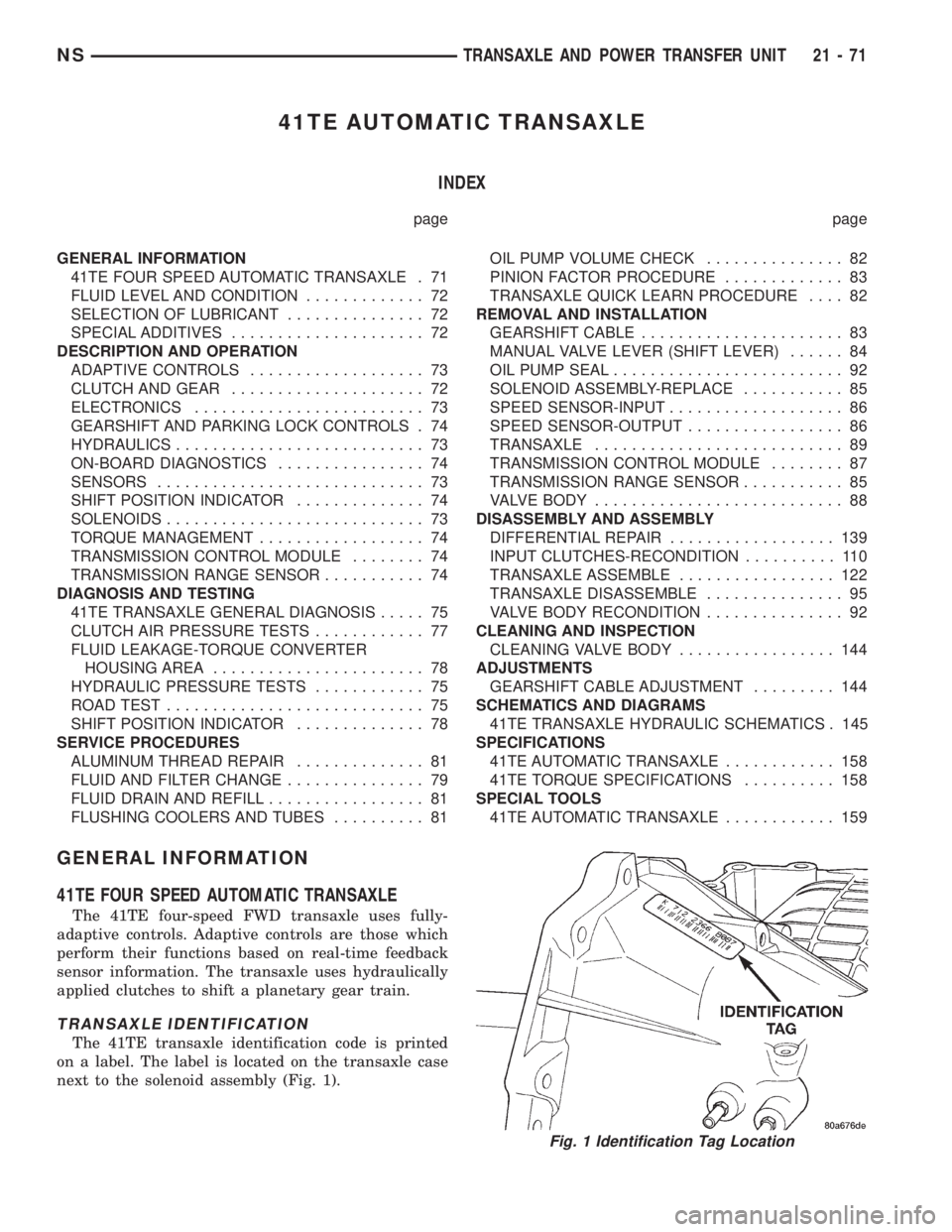
TRANSAXLE IDENTIFICATION
The 41TE transaxle identification code is printed
on a label. The label is located on the transaxle case
next to the solenoid assembly (Fig. 1).
Fig. 1 Identification Tag Location
NSTRANSAXLE AND POWER TRANSFER UNIT 21 - 71
Page 1547 of 1938
CAUTION: Some clutch packs appear similar, but
they are not the same. Do not interchange clutch
components, as they might fail.
HYDRAULICS
The hydraulics of the transaxle provide:
²Manual shift lever select function
²Main line pressure regulation
²Torque converter and cooler flow control
Oil flow to the friction elements is controlled
directly by four solenoid valves. The hydraulics also
include a unique logic- controlled solenoid torque con-
verter clutch control valve. This valve locks out the
1st gear reaction element with the application of 2nd,
direct, or overdrive gear elements. It also redirects
the 1st gear solenoid output so that it can control
torque converter clutch operation. To regain access to
1st gear, a sequence of commands must be used to
move the solenoid TCC control valve. This precludes
any application of the 1st gear reaction element with
other elements applied. It also allows one solenoid to
control two friction elements.
Small, high-rate accumulators are provided in each
controlled friction element circuit. These serve to
absorb the pressure responses, and allow the controls
to read and respond to changes that are occurring.
SOLENOIDS
The solenoid valves perform most control functions,
these valves must be extremely durable and tolerant
of dirt. For that reason hardened-steel poppet and
ball valves are used. These are free from any close
operating clearances. The solenoids operate the
valves directly without any intermediate element.
Direct operation means that these units must have
very high output. They must close against the size-
able flow areas and high line pressures. Fast
response is also required to meet the control require-
ments.
Two of the solenoids are normally-venting and two
are normally-applying; this was done to provide a
default mode of operation. With no electrical power,
the transmission provides 2nd gear in (OD), (3), or
(L) shift lever positions. All other transmission lever
positions will operate normally. The choice of 2nd
gear was made to provide adequate breakaway per-
formance while still accommodating highway speeds.
SENSORS
There are three pressure switches to identify sole-
noid application. There are two speed sensors to read
input (torque converter turbine) and output (parking
sprag) speeds. There is also a transmission range
sensor to indicate the manual shift lever position.
The pressure switches are incorporated in an assem-
bly with the solenoids. Engine speed, throttle posi-tion, temperature, etc., are also observed. Some of
these signals are read directly from the engine con-
trol sensors; others are read from a multiplex circuit
with the powertrain control module.
ELECTRONICS
The 41TE Transmission Control Module (TCM) is
located underhood in a potted, die-cast aluminum
housing. The module used is a new controller called
EATX III. The TCM has a sealed, 60-way connector.
ADAPTIVE CONTROLS
These controls function by reading the input and
output speeds over 140 times a second and respond-
ing to each new reading. This provides the precise
and sophisticated friction element control needed to
make smooth clutch-to-clutch shifts for all gear
changes. The use of overrunning clutches or other
shift quality aids are not required. As with most
automatic transaxles, all shifts involve releasing one
element and applying a different element. In simpli-
fied terms, the upshift logic allows the releasing ele-
ment to slip backwards slightly. This ensures that it
does not have excess capacity. The apply element is
filled until it begins to make the speed change to the
higher gear. The apply pressure is then controlled to
maintain the desired rate of speed change. This con-
tinues until the shift is made. The key to providing
excellent shift quality is precision. For example, the
release element for upshifts is allowed to slip back-
wards slightly. The amount of that slip is typically
less than a total of 20 degrees. To achieve that pre-
cision, the TCM learns the traits of the transaxle
that it is controlling. It learns the release rate of the
releasing element and the apply time of the applying
element. It also learns the rate at which the apply
element builds pressure sufficient to begin making
the speed change. This method achieves more preci-
sion than would be possible with exacting tolerances.
It can also adapt to any changes that occur with age
or environment.
For kickdown shifts, the control logic allows the
releasing element to slip. Then controls the rate at
which the input (and engine) accelerate. When the
lower gear speed is achieved, the releasing element
reapplies to maintain that speed until the apply ele-
ment is filled. This provides quick response since the
engine begins to accelerate immediately. This also
provides a smooth torque exchange since the release
element can control the rate of torque increase. This
control can make any powertrain feel more respon-
sive without increasing harshness.
Adaptive controls respond to input speed changes.
They compensate for changes in engine or friction
element torque and provide good, consistent shift
quality for the life of the transaxle.
NSTRANSAXLE AND POWER TRANSFER UNIT 21 - 73
DESCRIPTION AND OPERATION (Continued)