sensor CHRYSLER VOYAGER 1996 Service Manual
[x] Cancel search | Manufacturer: CHRYSLER, Model Year: 1996, Model line: VOYAGER, Model: CHRYSLER VOYAGER 1996Pages: 1938, PDF Size: 55.84 MB
Page 1566 of 1938
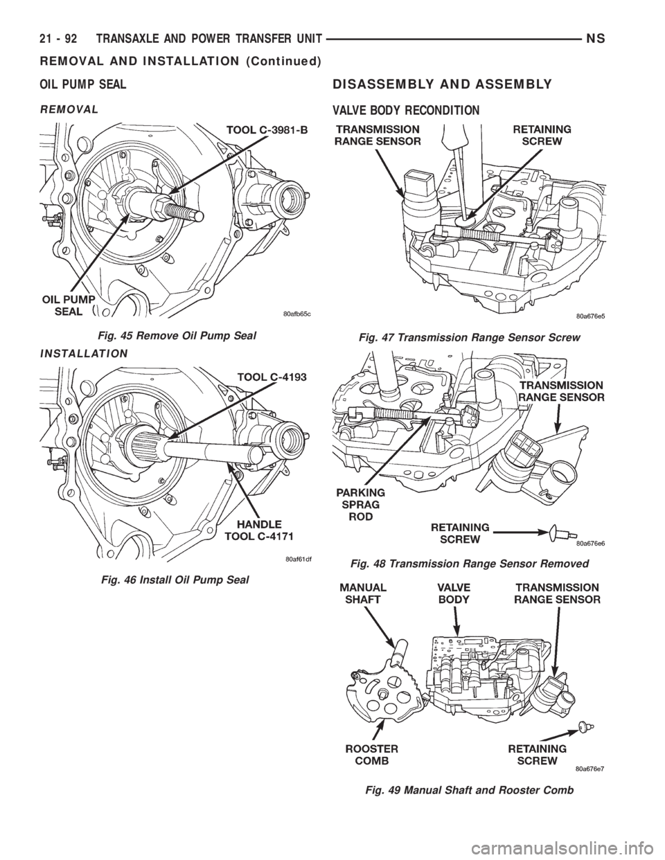
OIL PUMP SEAL
REMOVAL
INSTALLATION
DISASSEMBLY AND ASSEMBLY
VALVE BODY RECONDITION
Fig. 45 Remove Oil Pump Seal
Fig. 46 Install Oil Pump Seal
Fig. 47 Transmission Range Sensor Screw
Fig. 48 Transmission Range Sensor Removed
Fig. 49 Manual Shaft and Rooster Comb
21 - 92 TRANSAXLE AND POWER TRANSFER UNITNS
REMOVAL AND INSTALLATION (Continued)
Page 1569 of 1938

TRANSAXLE DISASSEMBLE
NOTE: Tag all clutch pack assemblies, as they are
removed, for reassembly identification.
CAUTION: Do not intermix clutch discs or plates as
the unit might then fail.
(1) Remove input and output speed sensors.
(2) Remove transaxle solenoid pack (Fig. 59).
Fig. 58 Low/Reverse Switch Valve And T/C Limit
Valve
Fig. 59 Remove Solenoid Pack
Fig. 60 Remove Oil Pan Bolts
Fig. 61 Remove Oil Pan
Fig. 62 Remove Oil Filter
NSTRANSAXLE AND POWER TRANSFER UNIT 21 - 95
DISASSEMBLY AND ASSEMBLY (Continued)
Page 1572 of 1938
Measure the input shaft end play with the tran-
saxle in the vertical position. This will ensure that
the measurement will be accurate.
Measuring input shaft end play before disassembly
will usually indicate when a #4 thrust plate change
is required. The #4 thrust plate is located behind the
overdrive clutch hub.
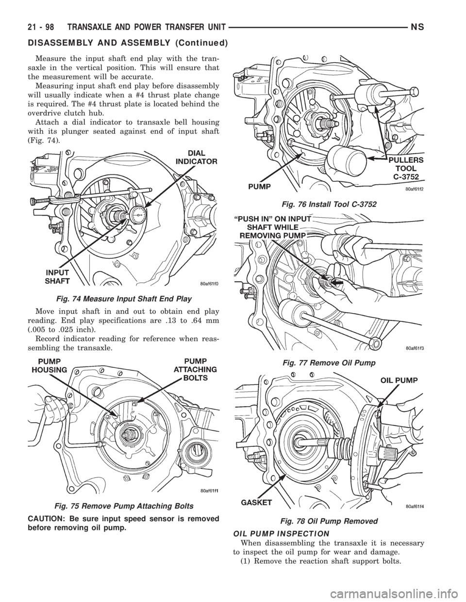
Attach a dial indicator to transaxle bell housing
with its plunger seated against end of input shaft
(Fig. 74).
Move input shaft in and out to obtain end play
reading. End play specifications are .13 to .64 mm
(.005 to .025 inch).
Record indicator reading for reference when reas-
sembling the transaxle.
CAUTION: Be sure input speed sensor is removed
before removing oil pump.
OIL PUMP INSPECTION
When disassembling the transaxle it is necessary
to inspect the oil pump for wear and damage.
(1) Remove the reaction shaft support bolts.
Fig. 74 Measure Input Shaft End Play
Fig. 75 Remove Pump Attaching Bolts
Fig. 76 Install Tool C-3752
Fig. 77 Remove Oil Pump
Fig. 78 Oil Pump Removed
21 - 98 TRANSAXLE AND POWER TRANSFER UNITNS
DISASSEMBLY AND ASSEMBLY (Continued)
Page 1608 of 1938
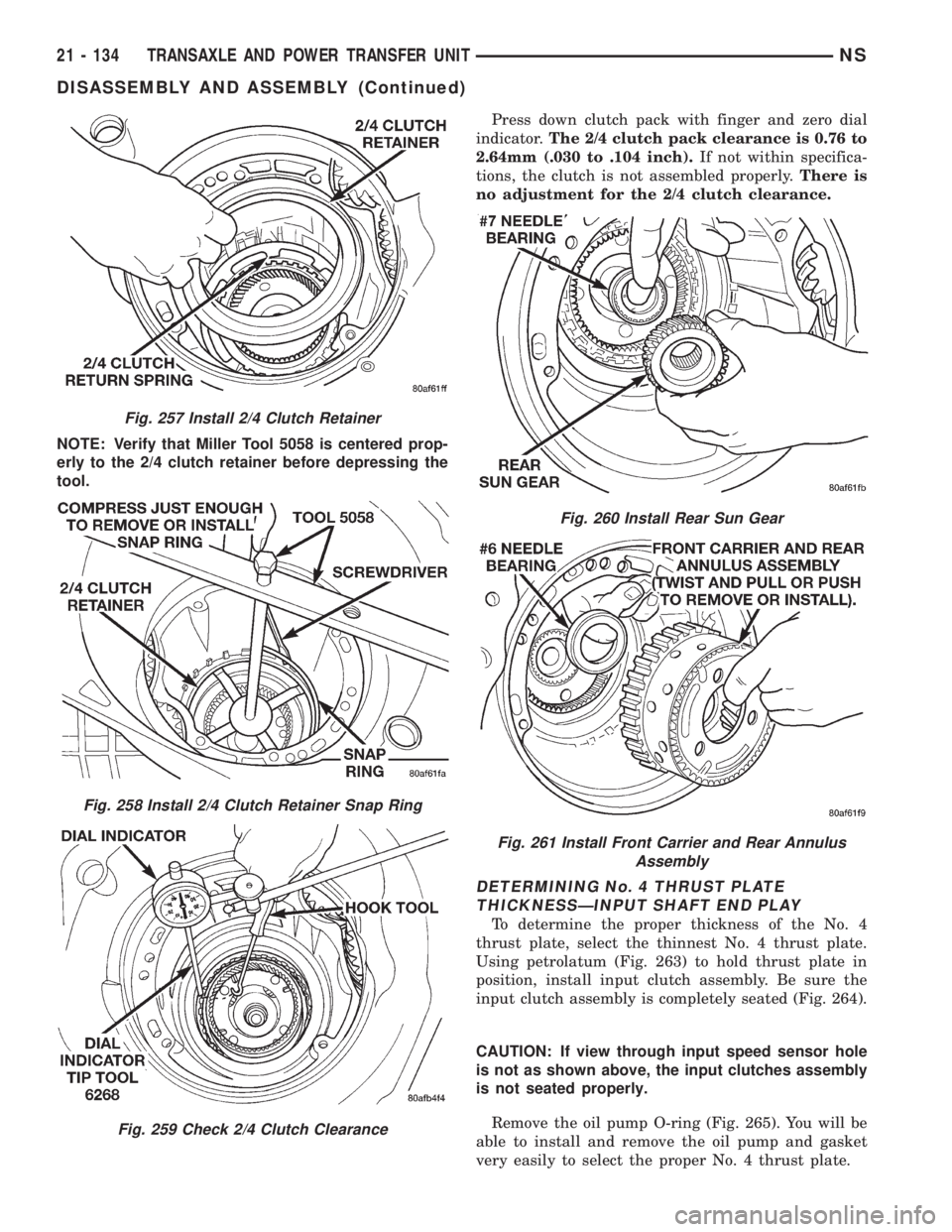
NOTE: Verify that Miller Tool 5058 is centered prop-
erly to the 2/4 clutch retainer before depressing the
tool.Press down clutch pack with finger and zero dial
indicator.The 2/4 clutch pack clearance is 0.76 to
2.64mm (.030 to .104 inch).If not within specifica-
tions, the clutch is not assembled properly.There is
no adjustment for the 2/4 clutch clearance.
DETERMINING No. 4 THRUST PLATE
THICKNESSÐINPUT SHAFT END PLAY
To determine the proper thickness of the No. 4
thrust plate, select the thinnest No. 4 thrust plate.
Using petrolatum (Fig. 263) to hold thrust plate in
position, install input clutch assembly. Be sure the
input clutch assembly is completely seated (Fig. 264).
CAUTION: If view through input speed sensor hole
is not as shown above, the input clutches assembly
is not seated properly.
Remove the oil pump O-ring (Fig. 265). You will be
able to install and remove the oil pump and gasket
very easily to select the proper No. 4 thrust plate.
Fig. 257 Install 2/4 Clutch Retainer
Fig. 258 Install 2/4 Clutch Retainer Snap Ring
Fig. 259 Check 2/4 Clutch Clearance
Fig. 260 Install Rear Sun Gear
Fig. 261 Install Front Carrier and Rear Annulus
Assembly
21 - 134 TRANSAXLE AND POWER TRANSFER UNITNS
DISASSEMBLY AND ASSEMBLY (Continued)
Page 1609 of 1938
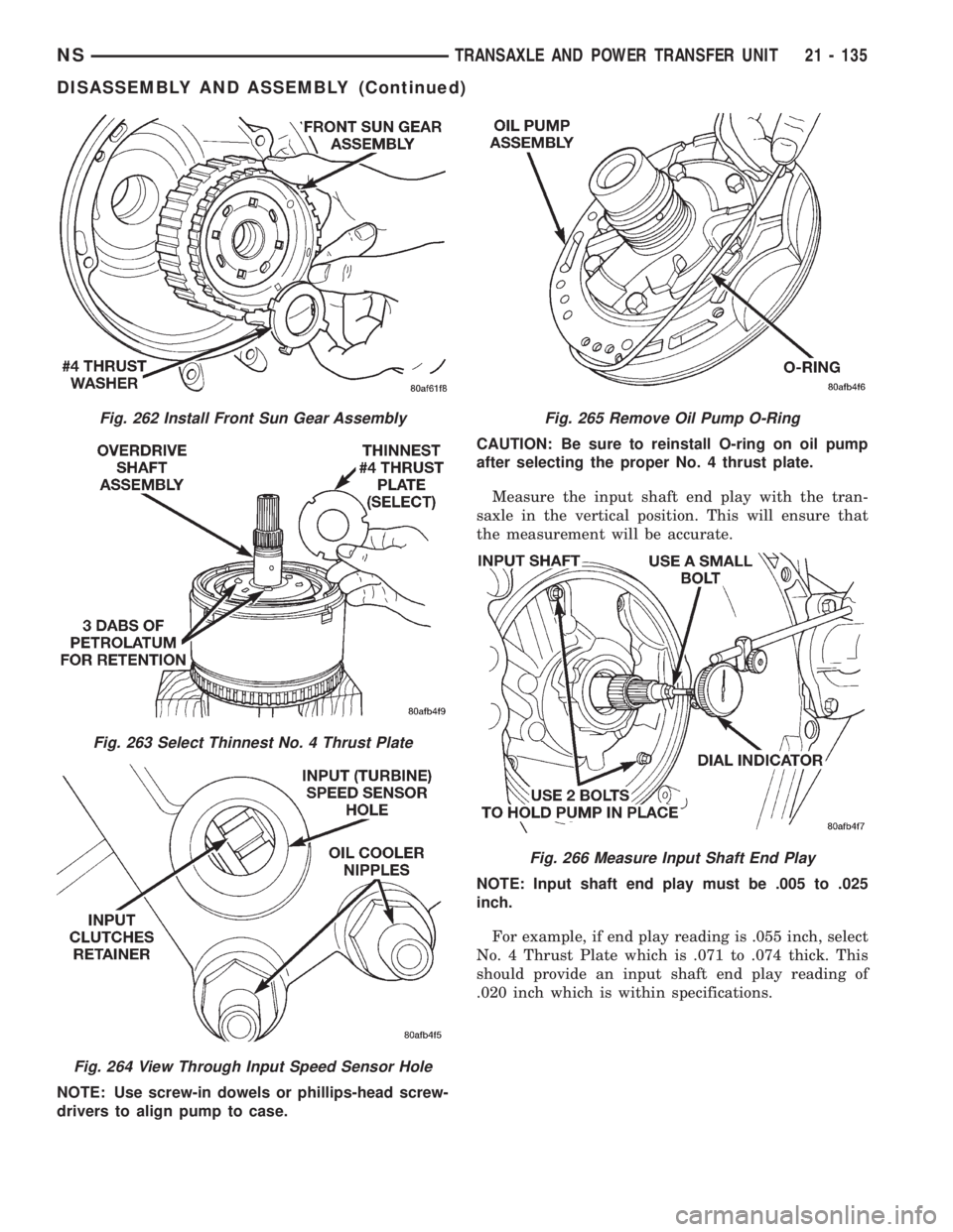
NOTE: Use screw-in dowels or phillips-head screw-
drivers to align pump to case.CAUTION: Be sure to reinstall O-ring on oil pump
after selecting the proper No. 4 thrust plate.
Measure the input shaft end play with the tran-
saxle in the vertical position. This will ensure that
the measurement will be accurate.
NOTE: Input shaft end play must be .005 to .025
inch.
For example, if end play reading is .055 inch, select
No. 4 Thrust Plate which is .071 to .074 thick. This
should provide an input shaft end play reading of
.020 inch which is within specifications.
Fig. 262 Install Front Sun Gear Assembly
Fig. 263 Select Thinnest No. 4 Thrust Plate
Fig. 264 View Through Input Speed Sensor Hole
Fig. 265 Remove Oil Pump O-Ring
Fig. 266 Measure Input Shaft End Play
NSTRANSAXLE AND POWER TRANSFER UNIT 21 - 135
DISASSEMBLY AND ASSEMBLY (Continued)
Page 1613 of 1938

(1) Install transaxle solenoid pack (Fig. 284).
(2) Install input and output speed sensors.
This concludes the assembly of the transaxle cen-
terline.
DIFFERENTIAL REPAIR
NOTE: The differential is serviced as an assembly.
The only parts that are serviceable within the differ-
ential are the differential bearing cups and cones. If
any other part fails within the differential, you must
replace the differential assembly along with the
transfer shaft.
DISASSEMBLE
The transfer shaft should be removed for differen-
tial repair and bearing turning torque checking.
(1) Remove the differential cover and bolts (Fig.
285) (Fig. 286).
(2) Remove the differential bearing retainer and
bolts (Fig. 287) (Fig. 288).(3) Using a plastic hammer, remove extension
housing/adapter plate on the right side of the tran-
saxle.
Fig. 283 Install Pan Bolts
Fig. 284 Install Solenoid Pack
Fig. 285 Differential Cover Bolts
Fig. 286 Remove Differential Cover
Fig. 287 Differential Retainer Bolts
NSTRANSAXLE AND POWER TRANSFER UNIT 21 - 139
DISASSEMBLY AND ASSEMBLY (Continued)
Page 1632 of 1938
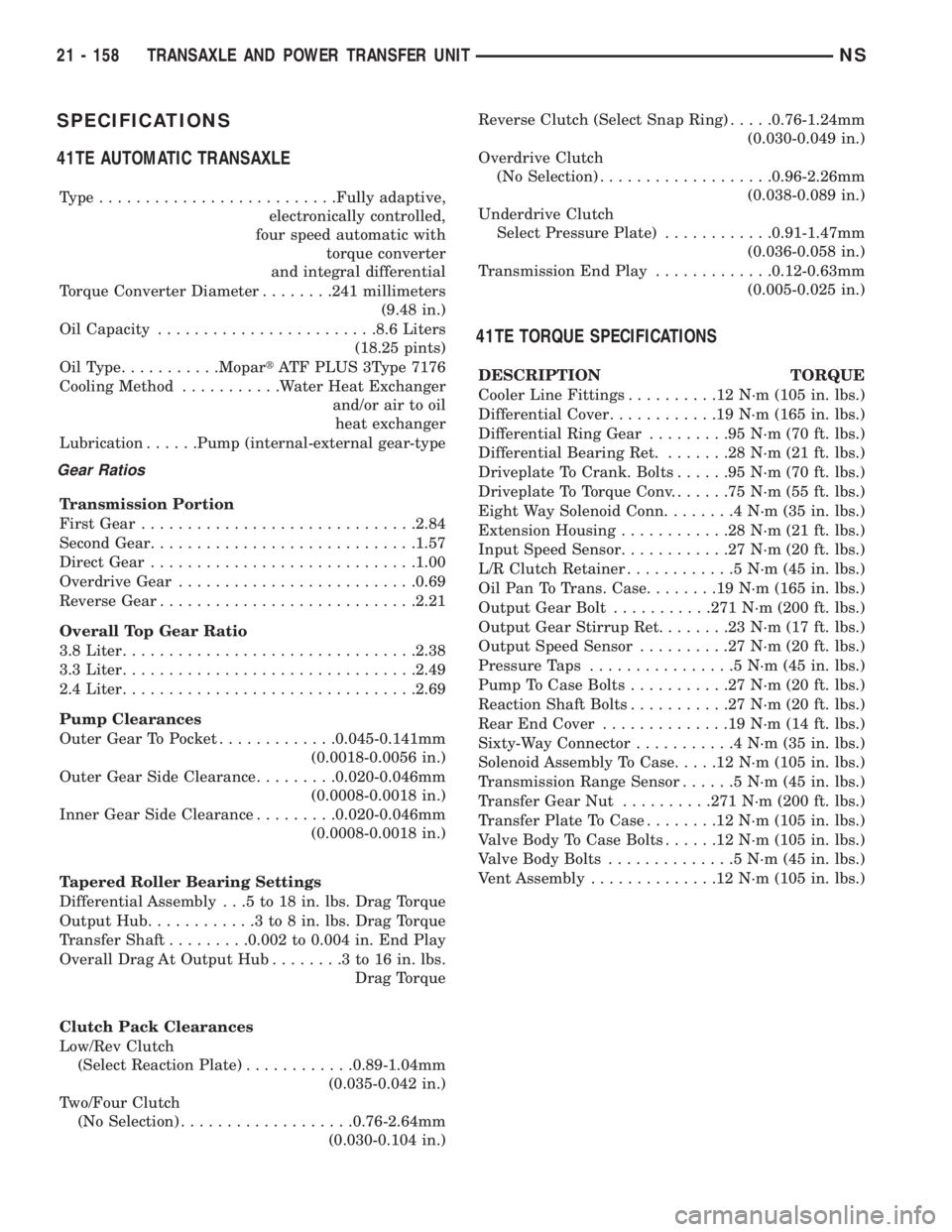
SPECIFICATIONS
41TE AUTOMATIC TRANSAXLE
Type..........................Fully adaptive,
electronically controlled,
four speed automatic with
torque converter
and integral differential
Torque Converter Diameter........241 millimeters
(9.48 in.)
Oil Capacity........................8.6 Liters
(18.25 pints)
OilType...........MopartATF PLUS 3Type 7176
Cooling Method...........Water Heat Exchanger
and/or air to oil
heat exchanger
Lubrication......Pump (internal-external gear-type
Gear Ratios
Transmission Portion
First Gear..............................2.84
Second Gear.............................1.57
Direct Gear.............................1.00
Overdrive Gear..........................0.69
Reverse Gear............................2.21
Overall Top Gear Ratio
3.8 Liter................................2.38
3.3 Liter................................2.49
2.4 Liter................................2.69
Pump Clearances
Outer Gear To Pocket.............0.045-0.141mm
(0.0018-0.0056 in.)
Outer Gear Side Clearance.........0.020-0.046mm
(0.0008-0.0018 in.)
Inner Gear Side Clearance.........0.020-0.046mm
(0.0008-0.0018 in.)
Tapered Roller Bearing Settings
Differential Assembly . . .5 to 18 in. lbs. Drag Torque
Output Hub............3to8in.lbs. Drag Torque
Transfer Shaft.........0.002 to 0.004 in. End Play
Overall Drag At Output Hub........3to16in.lbs.
Drag Torque
Clutch Pack Clearances
Low/Rev Clutch
(Select Reaction Plate)............0.89-1.04mm
(0.035-0.042 in.)
Two/Four Clutch
(No Selection)...................0.76-2.64mm
(0.030-0.104 in.)Reverse Clutch (Select Snap Ring).....0.76-1.24mm
(0.030-0.049 in.)
Overdrive Clutch
(No Selection)...................0.96-2.26mm
(0.038-0.089 in.)
Underdrive Clutch
Select Pressure Plate)............0.91-1.47mm
(0.036-0.058 in.)
Transmission End Play.............0.12-0.63mm
(0.005-0.025 in.)
41TE TORQUE SPECIFICATIONS
DESCRIPTION TORQUE
Cooler Line Fittings..........12N´m(105 in. lbs.)
Differential Cover............19N´m(165 in. lbs.)
Differential Ring Gear.........95N´m(70ft.lbs.)
Differential Bearing Ret........28N´m(21ft.lbs.)
Driveplate To Crank. Bolts......95N´m(70ft.lbs.)
Driveplate To Torque Conv.......75N´m(55ft.lbs.)
Eight Way Solenoid Conn........4N´m(35in.lbs.)
Extension Housing............28N´m(21ft.lbs.)
Input Speed Sensor............27N´m(20ft.lbs.)
L/R Clutch Retainer............5N´m(45in.lbs.)
Oil Pan To Trans. Case........19N´m(165 in. lbs.)
Output Gear Bolt...........271 N´m (200 ft. lbs.)
Output Gear Stirrup Ret........23N´m(17ft.lbs.)
Output Speed Sensor..........27N´m(20ft.lbs.)
Pressure Taps................5N´m(45in.lbs.)
Pump To Case Bolts...........27N´m(20ft.lbs.)
Reaction Shaft Bolts...........27N´m(20ft.lbs.)
Rear End Cover..............19N´m(14ft.lbs.)
Sixty-Way Connector...........4N´m(35in.lbs.)
Solenoid Assembly To Case.....12N´m(105 in. lbs.)
Transmission Range Sensor......5N´m(45in.lbs.)
Transfer Gear Nut..........271 N´m (200 ft. lbs.)
Transfer Plate To Case........12N´m(105 in. lbs.)
Valve Body To Case Bolts......12N´m(105 in. lbs.)
Valve Body Bolts..............5N´m(45in.lbs.)
Vent Assembly..............12N´m(105 in. lbs.)
21 - 158 TRANSAXLE AND POWER TRANSFER UNITNS
Page 1657 of 1938
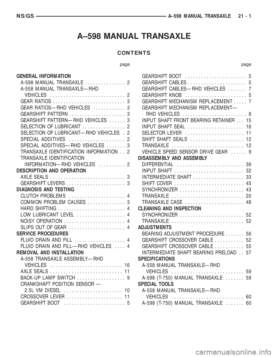
A±598 MANUAL TRANSAXLE
CONTENTS
page page
GENERAL INFORMATION
A-598 MANUAL TRANSAXLE............... 2
A-558 MANUAL TRANSAXLEÐRHD
VEHICLES............................ 2
GEAR RATIOS........................... 3
GEAR RATIOSÐRHD VEHICLES............ 3
GEARSHIFT PATTERN..................... 3
GEARSHIFT PATTERNÐRHD VEHICLES...... 3
SELECTION OF LUBRICANT................ 2
SELECTION OF LUBRICANTÐRHD VEHICLES . 2
SPECIAL ADDITIVES..................... 2
SPECIAL ADDITIVESÐRHD VEHICLES....... 3
TRANSAXLE IDENTIFICATION INFORMATION . . 2
TRANSAXLE IDENTIFICATION
INFORMATIONÐRHD VEHICLES.......... 2
DESCRIPTION AND OPERATION
AXLE SEALS............................ 3
GEARSHIFT LEVERS...................... 3
DIAGNOSIS AND TESTING
CLUTCH PROBLEMS..................... 4
COMMON PROBLEM CAUSES.............. 3
HARD SHIFTING......................... 4
LOW LUBRICANT LEVEL.................. 4
NOISY OPERATION....................... 4
SLIPS OUT OF GEAR..................... 4
SERVICE PROCEDURES
FLUID DRAIN AND FILL................... 4
FLUID DRAIN AND FILLÐRHD VEHICLES.... 4
REMOVAL AND INSTALLATION
A-558 TRANSAXLE ASSEMBLYÐRHD
VEHICLES........................... 16
AXLE SEALS........................... 11
BACK-UP LAMP SWITCH.................. 9
CRANKSHAFT POSITION SENSOR Ð
2.5L VM DIESEL...................... 10
CROSSOVER LEVER..................... 11
GEARSHIFT BOOT....................... 5GEARSHIFT BOOT....................... 5
GEARSHIFT CABLES...................... 5
GEARSHIFT CABLESÐRHD VEHICLES....... 7
GEARSHIFT KNOB....................... 5
GEARSHIFT MECHANISM REPLACEMENT..... 7
GEARSHIFT MECHANISM REPLACEMENTÐ
RHD VEHICLES........................ 8
INPUT SHAFT FRONT BEARING RETAINER . . . 15
INPUT SHAFT SEAL..................... 16
SELECTOR LEVER...................... 11
SHIFT SHAFT SEALS.................... 12
TRANSAXLE........................... 12
VEHICLE SPEED SENSOR DRIVE GEAR...... 9
DISASSEMBLY AND ASSEMBLY
DIFFERENTIAL......................... 39
INPUT SHAFT.......................... 32
INTERMEDIATE SHAFT................... 33
SHIFT COVER.......................... 45
SYNCHRONIZER........................ 43
TRANSAXLE........................... 20
TRANSAXLE CASE...................... 48
CLEANING AND INSPECTION
SYNCHRONIZER........................ 52
TRANSAXLE........................... 52
ADJUSTMENTS
BEARING ADJUSTMENT PROCEDURE....... 56
GEARSHIFT CROSSOVER CABLE........... 52
GEARSHIFT CROSSOVER CABLE........... 55
INTERMEDIATE SHAFT BEARING PRELOAD . . 57
SPECIFICATIONS
A-558 MANUAL TRANSAXLEÐRHD
VEHICLES........................... 59
A-598 (T-750) MANUAL TRANSAXLE....... 59
SPECIAL TOOLS
A-558 MANUAL TRANSAXLEÐRHD
VEHICLES........................... 60
A-598 (T-750) MANUAL TRANSAXLE....... 60
NS/GSA±598 MANUAL TRANSAXLE 21 - 1
Page 1665 of 1938
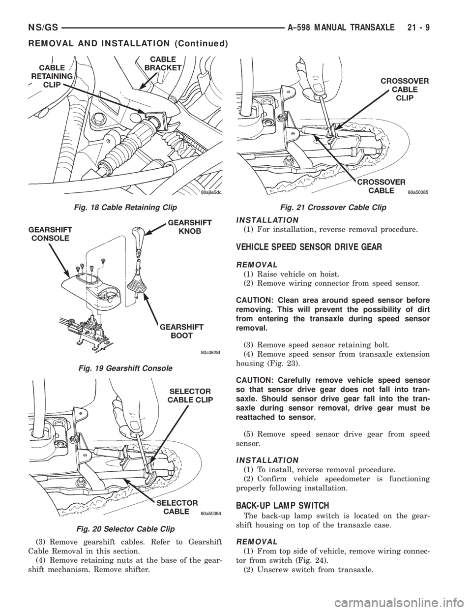
(3) Remove gearshift cables. Refer to Gearshift
Cable Removal in this section.
(4) Remove retaining nuts at the base of the gear-
shift mechanism. Remove shifter.
INSTALLATION
(1) For installation, reverse removal procedure.
VEHICLE SPEED SENSOR DRIVE GEAR
REMOVAL
(1) Raise vehicle on hoist.
(2) Remove wiring connector from speed sensor.
CAUTION: Clean area around speed sensor before
removing. This will prevent the possibility of dirt
from entering the transaxle during speed sensor
removal.
(3) Remove speed sensor retaining bolt.
(4) Remove speed sensor from transaxle extension
housing (Fig. 23).
CAUTION: Carefully remove vehicle speed sensor
so that sensor drive gear does not fall into tran-
saxle. Should sensor drive gear fall into the tran-
saxle during sensor removal, drive gear must be
reattached to sensor.
(5) Remove speed sensor drive gear from speed
sensor.
INSTALLATION
(1) To install, reverse removal procedure.
(2) Confirm vehicle speedometer is functioning
properly following installation.
BACK-UP LAMP SWITCH
The back-up lamp switch is located on the gear-
shift housing on top of the transaxle case.
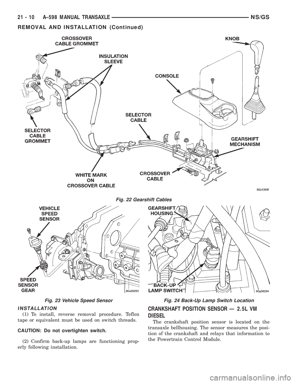
REMOVAL
(1) From top side of vehicle, remove wiring connec-
tor from switch (Fig. 24).
(2) Unscrew switch from transaxle.
Fig. 18 Cable Retaining Clip
Fig. 19 Gearshift Console
Fig. 20 Selector Cable Clip
Fig. 21 Crossover Cable Clip
NS/GSA±598 MANUAL TRANSAXLE 21 - 9
REMOVAL AND INSTALLATION (Continued)
Page 1666 of 1938
INSTALLATION
(1) To install, reverse removal procedure. Teflon
tape or equivalent must be used on switch threads.
CAUTION: Do not overtighten switch.
(2) Confirm back-up lamps are functioning prop-
erly following installation.
CRANKSHAFT POSITION SENSOR Ð 2.5L VM
DIESEL
The crankshaft position sensor is located on the
transaxle bellhousing. The sensor measures the posi-
tion of the crankshaft and relays that information to
the Powertrain Control Module.
Fig. 22 Gearshift Cables
Fig. 23 Vehicle Speed SensorFig. 24 Back-Up Lamp Switch Location
21 - 10 A±598 MANUAL TRANSAXLENS/GS
REMOVAL AND INSTALLATION (Continued)