display CHRYSLER VOYAGER 2001 Service Manual
[x] Cancel search | Manufacturer: CHRYSLER, Model Year: 2001, Model line: VOYAGER, Model: CHRYSLER VOYAGER 2001Pages: 4284, PDF Size: 83.53 MB
Page 1229 of 4284

Symptom:
*NO RESPONSE FROM ECM (PCI BUS) - DIESEL ONLY
POSSIBLE CAUSES
ECM PCI NO RESPONSE
PCI BUS CIRCUIT OPEN
ENGINE CONTROL MODULE
TEST ACTION APPLICABILITY
1 Turn the ignition on.
NOTE: As soon as one or more module communicates with the DRB, answer
the question.
With the DRB, enter Body then Body Computer.
With the DRB, enter Anti-Lock Brakes.
With the DRB, enter Body then Electro/Mechanical Cluster (MIC).
With the DRB, enter Passive Restraints then Airbag.
Were you able to establish communications with any of the modules?All
Ye s®Go To 2
No®Refer to symptom PCI Bus Communication Failure in the Com-
munications category.
Perform ROAD TEST VERIFICATION - VER-2.
2 With the DRB read ECM Diagnostic Trouble Codes. This is to ensure power and
grounds to the ECM are operational.
NOTE: If the DRB will not read ECM DTC's, follow the NO RESPONSE TO
ECM (SCI only) symptom path, if vehicle will start. For NO START Condi-
tions follow the no start symptom in the Starting category.
Turn the ignition off.
Disconnect the ECM harness connectors.
Use Scope input cable CH7058, Cable to Probe adapter CH7062, and the red and
black test probes.
Connect the scope input cable to the channel one connector on the DRB. Attach the
red and black leads and the cable to probe adapter to the scope input cable.
With the DRBIIItselect Pep Module Tools.
Select lab scope.
Select Live Data.
Select 12 volt square wave.
Press F2 for Scope.
Press F2 and use the down arrow to set voltage range to 20 volts. Press F2 again
when complete.
Connect the Black lead to ground. Connect the Red lead to the PCI Bus circuit in the
ECM connector.
Turn the ignition on.
Observe the voltage display on the DRB Lab Scope.
Does the voltage pulse from 0 to approximately 7.5 volts?All
Ye s®Replace and program the Engine Control Module in accordance
with the Service Information.
Perform ROAD TEST VERIFICATION - VER-2.
No®Repair the PCI Bus circuit for an open.
Perform ROAD TEST VERIFICATION - VER-2.
10
COMMUNICATION
Page 1233 of 4284

POSSIBLE CAUSES
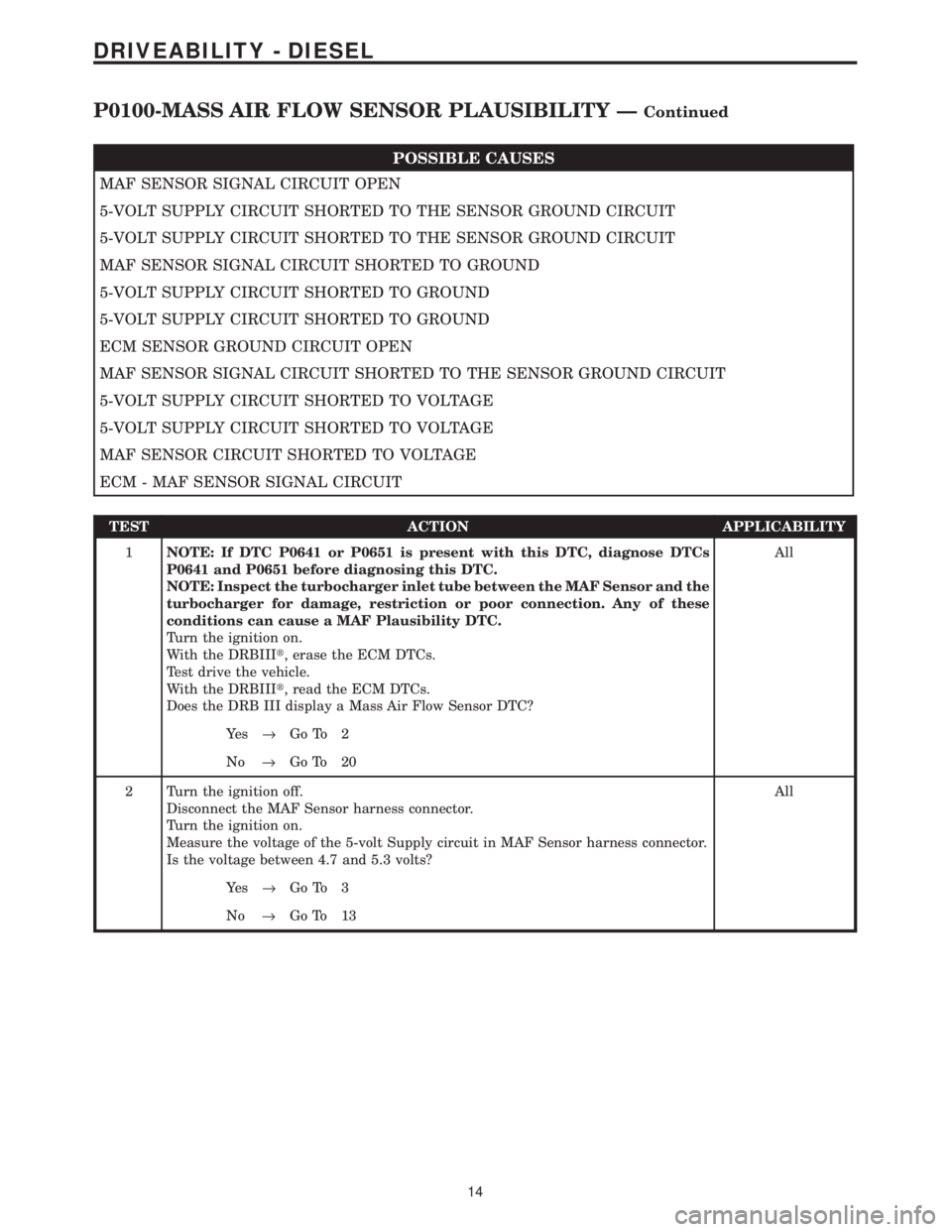
MAF SENSOR SIGNAL CIRCUIT OPEN
5-VOLT SUPPLY CIRCUIT SHORTED TO THE SENSOR GROUND CIRCUIT
5-VOLT SUPPLY CIRCUIT SHORTED TO THE SENSOR GROUND CIRCUIT
MAF SENSOR SIGNAL CIRCUIT SHORTED TO GROUND
5-VOLT SUPPLY CIRCUIT SHORTED TO GROUND
5-VOLT SUPPLY CIRCUIT SHORTED TO GROUND
ECM SENSOR GROUND CIRCUIT OPEN
MAF SENSOR SIGNAL CIRCUIT SHORTED TO THE SENSOR GROUND CIRCUIT
5-VOLT SUPPLY CIRCUIT SHORTED TO VOLTAGE
5-VOLT SUPPLY CIRCUIT SHORTED TO VOLTAGE
MAF SENSOR CIRCUIT SHORTED TO VOLTAGE
ECM - MAF SENSOR SIGNAL CIRCUIT
TEST ACTION APPLICABILITY
1NOTE: If DTC P0641 or P0651 is present with this DTC, diagnose DTCs
P0641 and P0651 before diagnosing this DTC.
NOTE: Inspect the turbocharger inlet tube between the MAF Sensor and the
turbocharger for damage, restriction or poor connection. Any of these
conditions can cause a MAF Plausibility DTC.
Turn the ignition on.
With the DRBIIIt, erase the ECM DTCs.
Test drive the vehicle.
With the DRBIIIt, read the ECM DTCs.
Does the DRB III display a Mass Air Flow Sensor DTC?All
Ye s®Go To 2
No®Go To 20
2 Turn the ignition off.
Disconnect the MAF Sensor harness connector.
Turn the ignition on.
Measure the voltage of the 5-volt Supply circuit in MAF Sensor harness connector.
Is the voltage between 4.7 and 5.3 volts?All
Ye s®Go To 3
No®Go To 13
14
DRIVEABILITY - DIESEL
P0100-MASS AIR FLOW SENSOR PLAUSIBILITY ÐContinued
Page 1234 of 4284

TEST ACTION APPLICABILITY
3 Turn the ignition off.
Disconnect the MAF Sensor harness connector.
Disconnect the ECM harness connectors.
Remove the ECM/PCM Relay from the PDC.
Connect a jumper wire between cavity 30 and cavity 87 of the ECM/PCM Relay
connector.
Turn the ignition on.
Measure the voltage of the MAF Sensor Signal circuit.
Is the voltage above 1.0 volt?All
Ye s®Repair the MAF Sensor Signal circuit for a short to voltage.
Perform ROAD TEST VERIFICATION - VER-2.
No®Go To 4
4 Turn the ignition off.
Disconnect the MAF Sensor harness connector.
Disconnect the ECM harness connectors.
Measure the resistance of the MAF Sensor Signal circuit.
Is the resistance below 10.0 ohms?All
Ye s®Go To 5
No®Repair the MAF Sensor Signal circuit for an open
Perform ROAD TEST VERIFICATION - VER-2.
5 Turn the ignition off.
Disconnect the MAF Sensor harness connector.
Disconnect the ECM harness connectors.
Measure the resistance between ground and the MAF Sensor Signal circuit.
Is the resistance below 1000 ohms?All
Ye s®Repair the MAF Sensor Signal circuit for a short to ground.
Perform ROAD TEST VERIFICATION - VER-2.
No®Go To 6
6 Turn the ignition off.
Disconnect the MAF Sensor harness connector.
Disconnect the ECM harness connectors.
Measure the resistance between the MAF Sensor Signal circuit and the Sensor
Ground circuit at of the MAF Sensor harness connector.
Is the resistance below 1000 ohms?All
Ye s®Repair the MAF Sensor Signal for a short to Sensor Ground .
Perform ROAD TEST VERIFICATION - VER-2.
No®Go To 7
7 Turn the ignition off.
Disconnect the MAF Sensor harness connector.
Connect a jumper wire between MAF Sensor Signal circuit and the 5-volt supply
circuit at the MAF Sensor harness connector .
With the DRBIII, read the MAF VOLTS.
Does the DRBIII display between 4.0 and 5.5 volts?All
Ye s®Go To 8
No®Replace and program the Engine Control Module in accordance
with the Service Information.
Perform ROAD TEST VERIFICATION - VER-2.
15
DRIVEABILITY - DIESEL
P0100-MASS AIR FLOW SENSOR PLAUSIBILITY ÐContinued
Page 1244 of 4284

TEST ACTION APPLICABILITY
3 Turn the ignition off.
Disconnect the ECM harness connectors.
Disconnect the Boost Pressure/IAT Sensor harness connector.
Measure the resistance of the Intake Air Temperature Sensor Signal circuit.
Is the resistance below 5.0 ohms?All
Ye s®Go To 4
No®Repair the Intake Air Temperature Sensor Signal circuit for an
open.
Perform ROAD TEST VERIFICATION - VER-2.
4 Turn the ignition off.
Disconnect the Boost Pressure/IAT Sensor harness connector.
Connect a jumper wire between the IAT Sensor Signal and IAT Sensor Ground
circuits in the Boost Pressure/IAT Sensor harness connector.
Turn the ignition on.
Monitor the DRB for ECM DTCs.
Does the DRB display P0110 INTAKE AIR TEMP. SENSOR CIRCUIT SIGNAL
VOLTAGE TOO LOW?All
Ye s®Replace the Turbocharger Boost Pressure/Intake Air Tempera-
ture Sensor.
Perform ROAD TEST VERIFICATION - VER-2.
No®Go To 5
5 Turn the ignition off.
Disconnect the Boost Pressure/IAT Sensor harness connector.
Disconnect the ECM harness connectors.
Measure the resistance of the Sensor Ground circuit between the ECM harness
connector and the Boost Pressure Sensor harness connector.
Monitor the DRB for ECM DTCs.
Is the resistance below 10.0 ohms?All
Ye s®Replace and program the Engine Control Module in accordance
with the Service Information.
Perform ROAD TEST VERIFICATION - VER-2.
No®Repair the Intake Air Temperature Sensor Ground circuit for an
open.
Perform ROAD TEST VERIFICATION - VER-2.
25
DRIVEABILITY - DIESEL
P0110-INTAKE AIR TEMP SENSOR CIRCUIT SIGNAL VOLTAGE TOO
HIGH Ð
Continued
Page 1246 of 4284

Symptom:
P0110-INTAKE AIR TEMP SENSOR CIRCUIT SIGNAL VOLTAGE
TOO LOW
When Monitored and Set Condition:
P0110-INTAKE AIR TEMP SENSOR CIRCUIT SIGNAL VOLTAGE TOO LOW
When Monitored: With the ignition on.
Set Condition: The Intake Air Temperature Sensor Signal voltage is below 0.21 volt.
POSSIBLE CAUSES
INTERMITTENT CONDITION
INTAKE AIR TEMP SENSOR SIGNAL CIRCUIT SHORTED TO GROUND
TURBOCHARGER BOOST PRESSURE/IAT SENSOR
ENGINE CONTROL MODULE
TEST ACTION APPLICABILITY
1 Turn the ignition on.
With the DRB, erase ECM DTCs.
Monitor the DRB for ECM DTCs.
Did this DTC reset?All
Ye s®Go To 2
No®Go To 5
2 Turn the ignition off.
Disconnect the ECM harness connectors.
Disconnect the Boost Pressure/IAT Sensor harness connector.
Measure the resistance between ground and the Intake Air Temperature Sensor
Signal circuit.
Is the resistance above 1000 ohms?All
Ye s®Go To 3
No®Repair the Intake Air Temperature Sensor Signal circuit for a
short to ground.
Perform ROAD TEST VERIFICATION - VER-2.
3 Turn the ignition off.
Disconnect the Boost Pressure/IAT Sensor harness connector.
Turn the ignition on.
Monitor the DRB for ECM DTCs.
Does the DRB display P0110 INTAKE AIR TEMP SIGNAL VOLTAGE TOO HIGH?All
Ye s®Replace the Turbocharger Boost Pressure/Intake Air Tempera-
ture Sensor.
Perform ROAD TEST VERIFICATION - VER-2.
No®Go To 4
27
DRIVEABILITY - DIESEL
Page 1266 of 4284

POSSIBLE CAUSES
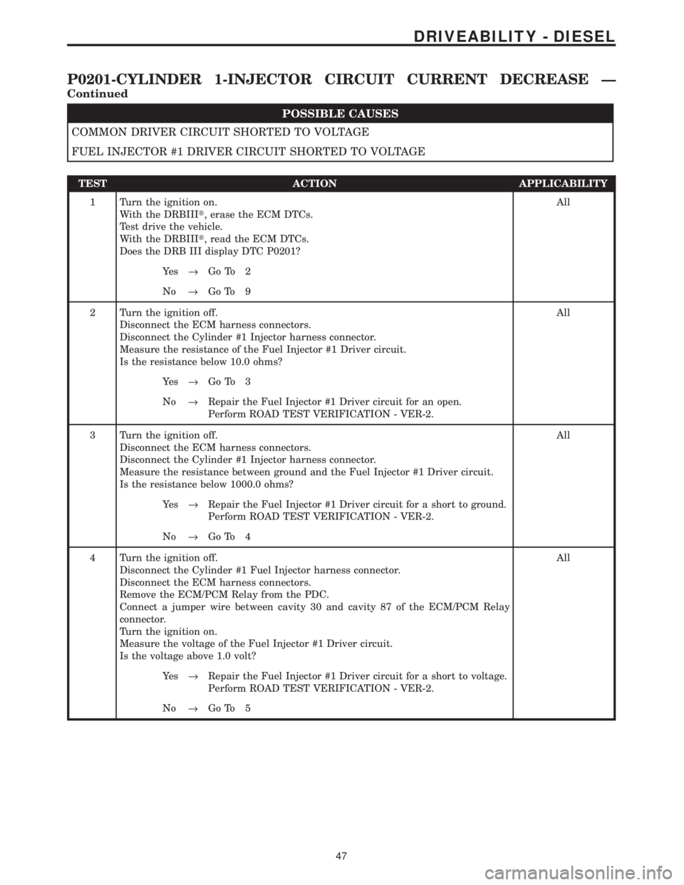
COMMON DRIVER CIRCUIT SHORTED TO VOLTAGE
FUEL INJECTOR #1 DRIVER CIRCUIT SHORTED TO VOLTAGE
TEST ACTION APPLICABILITY
1 Turn the ignition on.
With the DRBIIIt, erase the ECM DTCs.
Test drive the vehicle.
With the DRBIIIt, read the ECM DTCs.
Does the DRB III display DTC P0201?All
Ye s®Go To 2
No®Go To 9
2 Turn the ignition off.
Disconnect the ECM harness connectors.
Disconnect the Cylinder #1 Injector harness connector.
Measure the resistance of the Fuel Injector #1 Driver circuit.
Is the resistance below 10.0 ohms?All
Ye s®Go To 3
No®Repair the Fuel Injector #1 Driver circuit for an open.
Perform ROAD TEST VERIFICATION - VER-2.
3 Turn the ignition off.
Disconnect the ECM harness connectors.
Disconnect the Cylinder #1 Injector harness connector.
Measure the resistance between ground and the Fuel Injector #1 Driver circuit.
Is the resistance below 1000.0 ohms?All
Ye s®Repair the Fuel Injector #1 Driver circuit for a short to ground.
Perform ROAD TEST VERIFICATION - VER-2.
No®Go To 4
4 Turn the ignition off.
Disconnect the Cylinder #1 Fuel Injector harness connector.
Disconnect the ECM harness connectors.
Remove the ECM/PCM Relay from the PDC.
Connect a jumper wire between cavity 30 and cavity 87 of the ECM/PCM Relay
connector.
Turn the ignition on.
Measure the voltage of the Fuel Injector #1 Driver circuit.
Is the voltage above 1.0 volt?All
Ye s®Repair the Fuel Injector #1 Driver circuit for a short to voltage.
Perform ROAD TEST VERIFICATION - VER-2.
No®Go To 5
47
DRIVEABILITY - DIESEL
P0201-CYLINDER 1-INJECTOR CIRCUIT CURRENT DECREASE Ð
Continued
Page 1267 of 4284

TEST ACTION APPLICABILITY
5 Turn the ignition off.
Disconnect the ECM harness connectors.
Disconnect the Cylinder #1 Injector harness connector.
Measure the resistance of the Common Driver circuit.
Is the resistance below 10.0 ohms?All
Ye s®Go To 6
No®Repair the Common Driver circuit for an open.
Perform ROAD TEST VERIFICATION - VER-2.
6 Turn the ignition off.
Disconnect the ECM harness connectors.
Disconnect the Cylinder #1 Injector harness connector.
Measure the resistance between ground and the Common Driver circuit.
Is the resistance below 1000.0 ohms?All
Ye s®Repair the Common Driver circuit for a short to ground.
Perform ROAD TEST VERIFICATION - VER-2.
No®Go To 7
7 Turn the ignition off.
Disconnect the Cylinder #1 Fuel Injector harness connector.
Disconnect the ECM harness connectors.
Remove the ECM/PCM Relay from the PDC.
Connect a jumper wire between cavity 30 and cavity 87 of the ECM/PCM Relay
connector.
Turn the ignition on.
Measure the voltage of the Common Driver circuit.
Is the voltage above 1.0 volt?All
Ye s®Repair the Common Driver circuit for a short to voltage.
Perform ROAD TEST VERIFICATION - VER-2.
No®Go To 8
8 Turn the ignition off.
Replace the Cylinder #1 Fuel Injector in accordance with the Service Information.
With the DRBIIIt, erase the ECM DTCs.
Test drive the vehicle.
With the DRBIIIt, read the ECM DTCs.
Does the DRBIIItdisplay this DTC?All
Ye s®Replace and program the Engine Control Module in accordance
with the Service Information.
Perform ROAD TEST VERIFICATION - VER-2.
No®Test Complete.
48
DRIVEABILITY - DIESEL
P0201-CYLINDER 1-INJECTOR CIRCUIT CURRENT DECREASE Ð
Continued
Page 1270 of 4284

POSSIBLE CAUSES
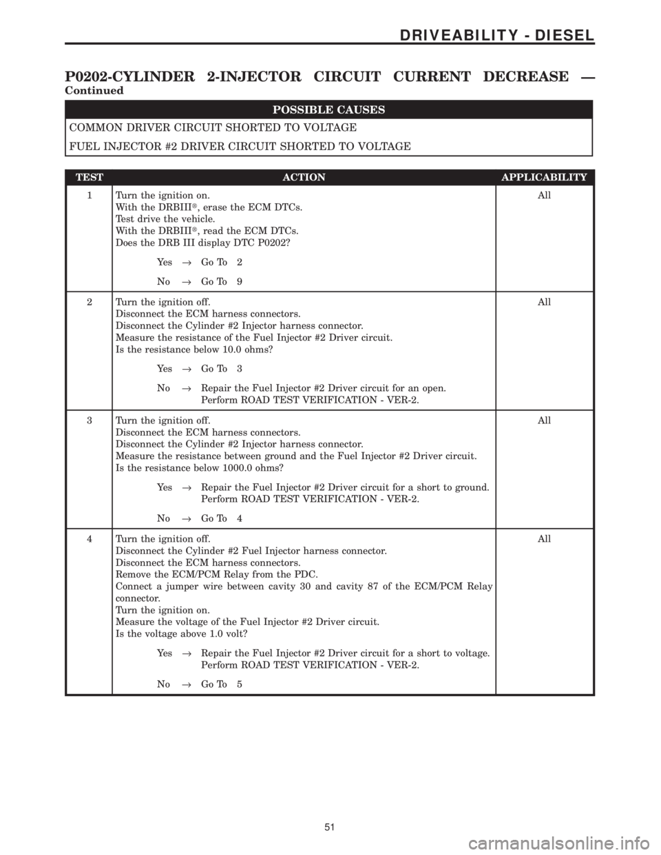
COMMON DRIVER CIRCUIT SHORTED TO VOLTAGE
FUEL INJECTOR #2 DRIVER CIRCUIT SHORTED TO VOLTAGE
TEST ACTION APPLICABILITY
1 Turn the ignition on.
With the DRBIIIt, erase the ECM DTCs.
Test drive the vehicle.
With the DRBIIIt, read the ECM DTCs.
Does the DRB III display DTC P0202?All
Ye s®Go To 2
No®Go To 9
2 Turn the ignition off.
Disconnect the ECM harness connectors.
Disconnect the Cylinder #2 Injector harness connector.
Measure the resistance of the Fuel Injector #2 Driver circuit.
Is the resistance below 10.0 ohms?All
Ye s®Go To 3
No®Repair the Fuel Injector #2 Driver circuit for an open.
Perform ROAD TEST VERIFICATION - VER-2.
3 Turn the ignition off.
Disconnect the ECM harness connectors.
Disconnect the Cylinder #2 Injector harness connector.
Measure the resistance between ground and the Fuel Injector #2 Driver circuit.
Is the resistance below 1000.0 ohms?All
Ye s®Repair the Fuel Injector #2 Driver circuit for a short to ground.
Perform ROAD TEST VERIFICATION - VER-2.
No®Go To 4
4 Turn the ignition off.
Disconnect the Cylinder #2 Fuel Injector harness connector.
Disconnect the ECM harness connectors.
Remove the ECM/PCM Relay from the PDC.
Connect a jumper wire between cavity 30 and cavity 87 of the ECM/PCM Relay
connector.
Turn the ignition on.
Measure the voltage of the Fuel Injector #2 Driver circuit.
Is the voltage above 1.0 volt?All
Ye s®Repair the Fuel Injector #2 Driver circuit for a short to voltage.
Perform ROAD TEST VERIFICATION - VER-2.
No®Go To 5
51
DRIVEABILITY - DIESEL
P0202-CYLINDER 2-INJECTOR CIRCUIT CURRENT DECREASE Ð
Continued
Page 1271 of 4284

TEST ACTION APPLICABILITY
5 Turn the ignition off.
Disconnect the ECM harness connectors.
Disconnect the Cylinder #2 Injector harness connector.
Measure the resistance of the Common Driver circuit.
Is the resistance below 10.0 ohms?All
Ye s®Go To 6
No®Repair the Common Driver circuit for an open.
Perform ROAD TEST VERIFICATION - VER-2.
6 Turn the ignition off.
Disconnect the ECM harness connectors.
Disconnect the Cylinder #2 Injector harness connector.
Measure the resistance between ground and the Common Driver circuit.
Is the resistance below 1000.0 ohms?All
Ye s®Repair the Common Driver circuit for a short to ground.
Perform ROAD TEST VERIFICATION - VER-2.
No®Go To 7
7 Turn the ignition off.
Disconnect the Cylinder #2 Fuel Injector harness connector.
Disconnect the ECM harness connectors.
Remove the ECM/PCM Relay from the PDC.
Connect a jumper wire between cavity 30 and cavity 87 of the ECM/PCM Relay
connector.
Turn the ignition on.
Measure the voltage of the Common Driver circuit.
Is the voltage above 1.0 volt?All
Ye s®Repair the Common Driver circuit for a short to voltage.
Perform ROAD TEST VERIFICATION - VER-2.
No®Go To 8
8 Turn the ignition off.
Replace the Cylinder #2 Fuel Injector in accordance with the Service Information.
With the DRBIIIt, erase the ECM DTCs.
Test drive the vehicle.
With the DRBIIIt, read the ECM DTCs.
Does the DRBIIItdisplay this DTC?All
Ye s®Replace and program the Engine Control Module in accordance
with the Service Information.
Perform ROAD TEST VERIFICATION - VER-2.
No®Test Complete.
52
DRIVEABILITY - DIESEL
P0202-CYLINDER 2-INJECTOR CIRCUIT CURRENT DECREASE Ð
Continued
Page 1274 of 4284

POSSIBLE CAUSES
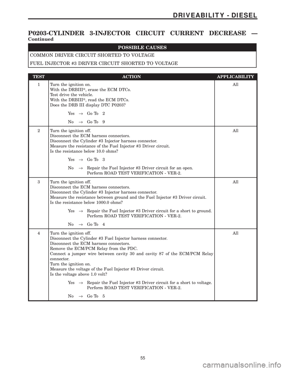
COMMON DRIVER CIRCUIT SHORTED TO VOLTAGE
FUEL INJECTOR #3 DRIVER CIRCUIT SHORTED TO VOLTAGE
TEST ACTION APPLICABILITY
1 Turn the ignition on.
With the DRBIIIt, erase the ECM DTCs.
Test drive the vehicle.
With the DRBIIIt, read the ECM DTCs.
Does the DRB III display DTC P0203?All
Ye s®Go To 2
No®Go To 9
2 Turn the ignition off.
Disconnect the ECM harness connectors.
Disconnect the Cylinder #3 Injector harness connector.
Measure the resistance of the Fuel Injector #3 Driver circuit.
Is the resistance below 10.0 ohms?All
Ye s®Go To 3
No®Repair the Fuel Injector #3 Driver circuit for an open.
Perform ROAD TEST VERIFICATION - VER-2.
3 Turn the ignition off.
Disconnect the ECM harness connectors.
Disconnect the Cylinder #3 Injector harness connector.
Measure the resistance between ground and the Fuel Injector #3 Driver circuit.
Is the resistance below 1000.0 ohms?All
Ye s®Repair the Fuel Injector #3 Driver circuit for a short to ground.
Perform ROAD TEST VERIFICATION - VER-2.
No®Go To 4
4 Turn the ignition off.
Disconnect the Cylinder #3 Fuel Injector harness connector.
Disconnect the ECM harness connectors.
Remove the ECM/PCM Relay from the PDC.
Connect a jumper wire between cavity 30 and cavity 87 of the ECM/PCM Relay
connector.
Turn the ignition on.
Measure the voltage of the Fuel Injector #3 Driver circuit.
Is the voltage above 1.0 volt?All
Ye s®Repair the Fuel Injector #3 Driver circuit for a short to voltage.
Perform ROAD TEST VERIFICATION - VER-2.
No®Go To 5
55
DRIVEABILITY - DIESEL
P0203-CYLINDER 3-INJECTOR CIRCUIT CURRENT DECREASE Ð
Continued