window CHRYSLER VOYAGER 2001 Owner's Guide
[x] Cancel search | Manufacturer: CHRYSLER, Model Year: 2001, Model line: VOYAGER, Model: CHRYSLER VOYAGER 2001Pages: 4284, PDF Size: 83.53 MB
Page 1898 of 4284
OPERATION
The Rear Window Defogger (Fig. 1) system consists
of two vertical bus bars linked by a series of grid
lines on the inside surface of the rear window. The
electrical circuit consists of the rear defogger switch
in the HVAC control assembly and a relay with timer
switch to turn OFF the system after ten minutes.
The main feed circuit is protected by fuse 13 (40
amp) in the Power Distribution Center (PDC) which
is integrated as a unit call Integrated Power Module
(IPM). The rear defogger switch and relay also acti-
vates the heated power side view mirrors and heated
windshield wiper de-icer. The heated windshield
wiper de-icer is powered by the RUN/ACC relay in
the IPM and feed thru fuse #11 (20 amp) in the PDC.
The heated mirror circuit is protected by a non-servi-
cable Positive Temperature Coefficient (PTC) located
inside the PDC. The heated windshield wiper de-icer
circuit is protected by fuse 11 (20 amp) in the PDC.
The Heated Windshield Wiper Deicer is also acti-
vated when the DEFROST mode is selected on the
HVAC. In the DEFROST mode the rear defogger
relay/timer is bypassed, the heated windshield wiper
de-icer will stay ON until the another mode is
selected. For circuit information and component loca-
tion refer to appropriate section for Wiring Diagrams.
CAUTION:
Since grid lines can be damaged or scraped off
with sharp instruments, care should be taken in
cleaning the glass or removing foreign materials,
decals or stickers. Normal glass cleaning solvents
or hot water used with rags or toweling is recom-
mended.
DEFOGGER RELAY
DESCRIPTION
There is no heated glass relay it is integrated into
the (E.B.L) relay that is located in the IPM in the
engine compartment.
REAR WINDOW DEFOGGER
GRID
STANDARD PROCEDURE - GRID LINE
REPAIR-REAR
For Grid repair procedure for the rear window
defogger (Refer to 8 - ELECTRICAL/HEATED
GLASS/WINDSHIELD GRID - STANDARD PROCE-
DURE).
REAR WINDOW DEFOGGER
SWITCH
DESCRIPTION
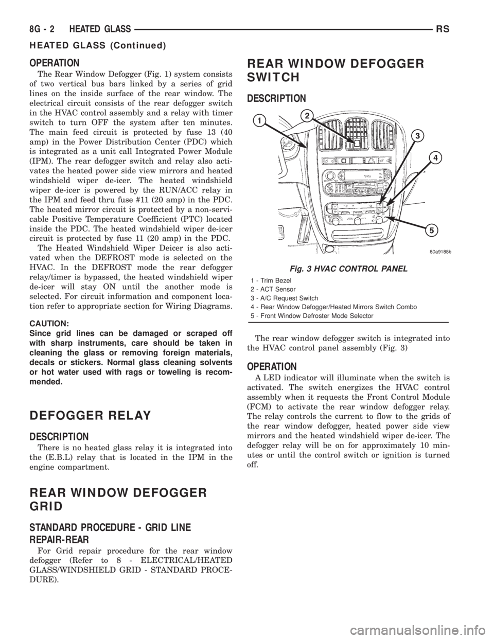
The rear window defogger switch is integrated into
the HVAC control panel assembly (Fig. 3)
OPERATION
A LED indicator will illuminate when the switch is
activated. The switch energizes the HVAC control
assembly when it requests the Front Control Module
(FCM) to activate the rear window defogger relay.
The relay controls the current to flow to the grids of
the rear window defogger, heated power side view
mirrors and the heated windshield wiper de-icer. The
defogger relay will be on for approximately 10 min-
utes or until the control switch or ignition is turned
off.
Fig. 3 HVAC CONTROL PANEL
1 - Trim Bezel
2 - ACT Sensor
3 - A/C Request Switch
4 - Rear Window Defogger/Heated Mirrors Switch Combo
5 - Front Window Defroster Mode Selector
8G - 2 HEATED GLASSRS
HEATED GLASS (Continued)
Page 1899 of 4284
WINDSHIELD GRID
DIAGNOSIS AND TESTING - SYSTEM TEST
Electrically heated rear window defogger or the
heated windshield wiper deicer operation can be
checked on the vehicle in the following manner:
(1) Turn the ignition switch to the ON position.
(2) Using a ammeter on the battery, turn the rear
defogger control switch to the ON position, a distinct
increase in amperage draw should be noted.
(3) The rear window defogger or the heated wind-
shield wiper deicer operation can be checked by feel-
ing the glass. A distinct difference in temperature
between the grid lines and adjacent clear glass can
be detected in 3 to 4 minutes of operation.
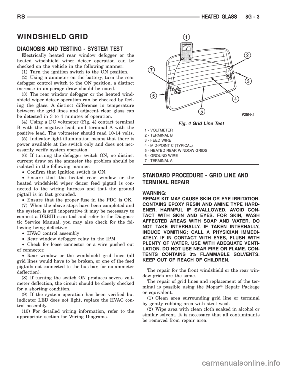
(4) Using a DC voltmeter (Fig. 4) contact terminal
B with the negative lead, and terminal A with the
positive lead. The voltmeter should read 10-14 volts.
(5) Indicator light illumination means that there is
power available at the switch only and does not nec-
essarily verify system operation.
(6) If turning the defogger switch ON, no distinct
current draw on the ammeter the problem should be
isolated in the following manner:
²Confirm that ignition switch is ON.
²Ensure that the heated rear window or the
heated windshield wiper deicer feed pigtail is con-
nected to the wiring harness and that the ground
pigtail is in fact grounded.
²Ensure that the proper fuse in the PDC is OK.
(7) When the above steps have been completed and
the system is still inoperative it may be necessary to
connect a DRBIII scan tool and refer to the Diagnos-
tic Service Manual, you may also check for the fol-
lowing being defective:
²HVAC control assembly
²Rear window defogger relay in the IPM.
²Check for loose connector or a wire pushed out
of connector.
²Rear window or the windshield grid lines (all
grid lines would have to be broken, or one of the feed
pigtails not connected to the bus bar, for no ammeter
deflection).
(8) If turning the switch ON produces severe volt-
meter deflection, the circuit should be closely checked
for a shorting condition.
(9) If the system operation has been verified but
indicator LED does not light, replace the HVAC con-
trol assembly.
(10) For detailed wiring information, refer to the
appropriate section for Wiring Diagrams.
STANDARD PROCEDURE - GRID LINE AND
TERMINAL REPAIR
WARNING:
REPAIR KIT MAY CAUSE SKIN OR EYE IRRITATION.
CONTAINS EPOXY RESIN AND AMINE TYPE HARD-
ENER, HARMFUL IF SWALLOWED. AVOID CON-
TACT WITH SKIN AND EYES. FOR SKIN, WASH
AFFECTED AREAS WITH SOAP AND WATER. DO
NOT TAKE INTERNALLY. IF TAKEN INTERNALLY,
INDUCE VOMITING; CALL A PHYSICIAN IMMEDI-
ATELY. IF IN CONTACT WITH EYES, FLUSH WITH
PLENTY OF WATER. USE WITH ADEQUATE VENTI-
LATION. DO NOT USE NEAR FIRE OR FLAME. CON-
TENTS CONTAINS 3% FLAMMABLE SOLVENTS.
KEEP OUT OF REACH OF CHILDREN.
The repair for the front windshield or the rear win-
dow grids are the same.
The repair of grid lines and replacement of the ter-
minal is possible using the MopartRepair Package
or equivalent.
(1) Clean area surrounding grid line or terminal
by gently rubbing area with steel wool.
(2) Wipe area with clean cloth soaked in alcohol or
similar solvent. It is necessary that all contaminants
be removed from repair area.
Fig. 4 Grid Line Test
1 - VOLTMETER
2 - TERMINAL B
3 - FEED WIRE
4 - MID-POINT C (TYPICAL)
5 - HEATED REAR WINDOW GRIDS
6 - GROUND WIRE
7 - TERMINAL A
RSHEATED GLASS8G-3
Page 1900 of 4284
(3) Remove package separator clamp and mix plas-
tic conductive epoxy thoroughly.
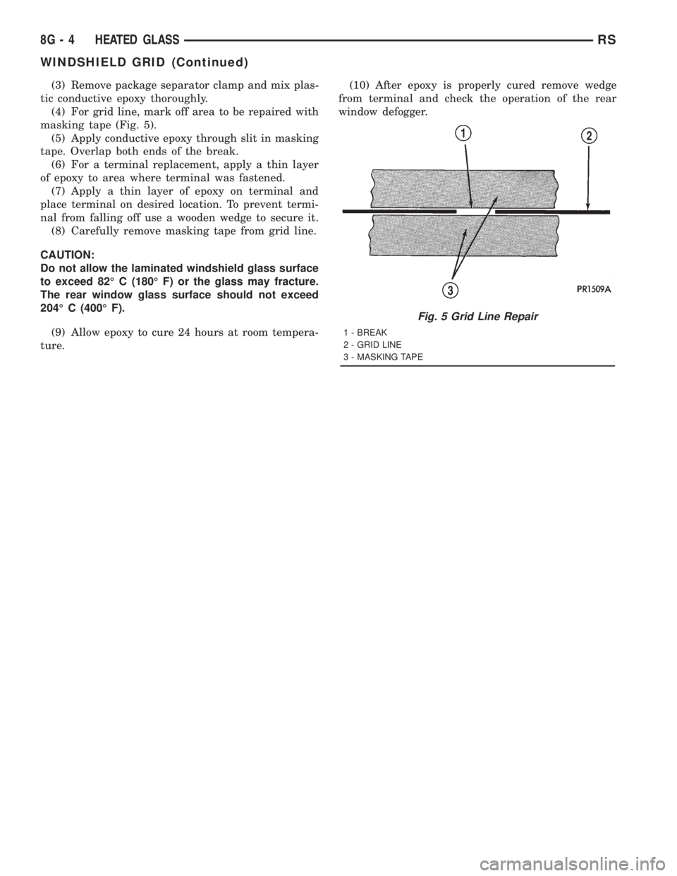
(4) For grid line, mark off area to be repaired with
masking tape (Fig. 5).
(5) Apply conductive epoxy through slit in masking
tape. Overlap both ends of the break.
(6) For a terminal replacement, apply a thin layer
of epoxy to area where terminal was fastened.
(7) Apply a thin layer of epoxy on terminal and
place terminal on desired location. To prevent termi-
nal from falling off use a wooden wedge to secure it.
(8) Carefully remove masking tape from grid line.
CAUTION:
Do not allow the laminated windshield glass surface
to exceed 82É C (180É F) or the glass may fracture.
The rear window glass surface should not exceed
204É C (400É F).
(9) Allow epoxy to cure 24 hours at room tempera-
ture.(10) After epoxy is properly cured remove wedge
from terminal and check the operation of the rear
window defogger.
Fig. 5 Grid Line Repair
1 - BREAK
2 - GRID LINE
3 - MASKING TAPE
8G - 4 HEATED GLASSRS
WINDSHIELD GRID (Continued)
Page 1901 of 4284
HEATED MIRRORS
TABLE OF CONTENTS
page page
HEATED MIRRORS
DESCRIPTION............................5
OPERATION.............................5
DIAGNOSIS AND TESTING..................5
HEATED MIRROR TEST...................5
MIRROR SWITCH
DESCRIPTION............................5OPERATION.............................5
HEATED MIRROR GRID
STANDARD PROCEDURE...................6
HEATED MIRROR.......................6
RELAY
DESCRIPTION............................6
HEATED MIRRORS
DESCRIPTION
Heated mirrors are available on models with
Power Mirrors and Rear Window Defogger only.
OPERATION
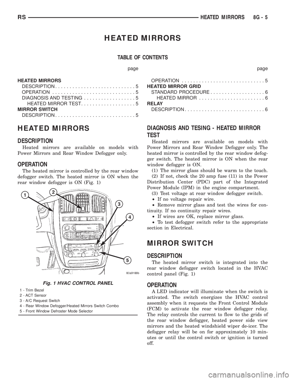
The heated mirror is controlled by the rear window
defogger switch. The heated mirror is ON when the
rear window defogger is ON (Fig. 1)
DIAGNOSIS AND TESING - HEATED MIRROR
TEST
Heated mirrors are available on models with
Power Mirrors and Rear Window Defogger only. The
heated mirror is controlled by the rear window defog-
ger switch. The heated mirror is ON when the rear
window defogger is ON.
(1) The mirror glass should be warm to the touch.
(2) If not, check the 20 amp fuse (11) in the Power
Distribution Center (PDC) part of the Integrated
Power Module (IPM) in the engine compartment.
(3) Test voltage at rear window defogger switch.
²If no voltage repair wire.
²Remove mirror glass and test the wires for con-
tinuity. If no continuity repair wires.
²If wires are OK, replace mirror glass.
²To test defogger switch refer to the appropriate
section in Electrical.
MIRROR SWITCH
DESCRIPTION
The heated mirror switch is integrated into the
rear window defogger switch located in the HVAC
control panel (Fig. 1)
OPERATION
A LED indicator will illuminate when the switch is
activated. The switch energizes the HVAC control
assembly when it requests the Front Control Module
(FCM) to activate the rear window defogger relay.
The relay controls the current to flow to the grids of
the rear window defogger, heated power side view
mirrors and the heated windshield wiper de-icer. The
defogger relay will be on for approximately 10 min-
utes or until the control switch or ignition is turned
off.
Fig. 1 HVAC CONTROL PANEL
1 - Trim Bezel
2 - ACT Sensor
3 - A/C Request Switch
4 - Rear Window Defogger/Heated Mirrors Switch Combo
5 - Front Window Defroster Mode Selector
RSHEATED MIRRORS8G-5
Page 1904 of 4284
²Remote Keyless Entry Module (RKE)- Refer
toRemote Keyless Entry Modulein Power Locks
for more information.
²Electronic Vehicle Information Center
(EVIC)- Refer toElectronic Vehicle Information
Centerin Overhead Console for more information.
²Heated Seat Module (HSM)- Refer toHeated
Seat Modulein Electronic Control Modules for more
information.
²Memory Heated Seat Module (MHSM)-If
the vehicle is equipped with the Memory System,
refer toMemory Seat Mirror Module (MSMM)in
Electronic Control Modules for more information.
Refer toWiring Diagramsfor complete circuit
diagrams. Following are general descriptions of the
major components in the heated seat system.
OPERATION
The heated seat system will only operate when the
ignition switch is in the On position, and the surface
temperature at the front seat heating element sen-
sors is below the designed temperature set points of
the system. The heated seat system will not operate
in ambient temperatures greater than about 41É C
(105É F). The front seat heating elements and sensors
are hard wired to the Heated Seat Module (HSM) or
the Memory Heated Seat Module (MHSM).
The heated seat switches are hard wired to the
Body Control Module (BCM). The BCM monitors the
heated seat switch inputs, then sends heated seat
switch status messages to the HSM or MHSM over
the Programmable Communications Interface J1850
(PCI) data bus. The HSM or MHSM contains the con-
trol logic for the heated seat system. The HSM or
MHSM responds to the heated seat switch status
messages, ignition switch status messages, and the
front seat heating element sensor inputs by control-
ling the output to the front seat heating elements
through integral solid-state relays.
When a seat heater is turned on, the sensor
located on the seat cushion electric heater element
provides the HSM or MHSM with an input indicating
the surface temperature of the seat cushion. If the
surface temperature input is below the temperature
set point for the selected Low or High heated seat
switch position, the HSM or MHSM energizes the
integral solid-state relay, which supplies battery cur-
rent to the heating elements in the seat cushion and
back. When the sensor input indicates the correct
temperature set point has been achieved, the HSM or
MHSM de-energizes the solid-state relay. The HSM
or MHSM will continue to cycle the solid-state relay
as needed to maintain the temperature set point.
The HSM or MHSM and the seat heater elements
operate on non-switched battery current supplied
through the power seat fuse in the intelligent powermodule. However, the HSM or MHSM will automati-
cally turn off the heating elements if it detects an
open in the sensor circuit, a short in the heating ele-
ment circuit causing an excessive current draw, or
when the ignition switch is turned to the Off posi-
tion.
See the owner's manual in the vehicle glove box for
more information on the features, use and operation
of the heated seat system.
DRIVER HEATED SEAT
SWITCH
DESCRIPTION
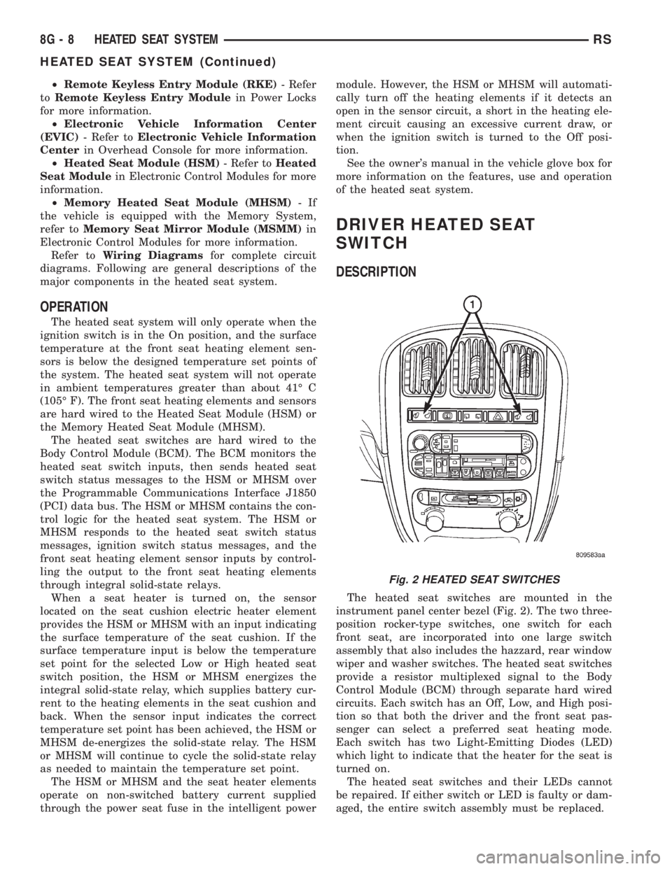
The heated seat switches are mounted in the
instrument panel center bezel (Fig. 2). The two three-
position rocker-type switches, one switch for each
front seat, are incorporated into one large switch
assembly that also includes the hazzard, rear window
wiper and washer switches. The heated seat switches
provide a resistor multiplexed signal to the Body
Control Module (BCM) through separate hard wired
circuits. Each switch has an Off, Low, and High posi-
tion so that both the driver and the front seat pas-
senger can select a preferred seat heating mode.
Each switch has two Light-Emitting Diodes (LED)
which light to indicate that the heater for the seat is
turned on.
The heated seat switches and their LEDs cannot
be repaired. If either switch or LED is faulty or dam-
aged, the entire switch assembly must be replaced.
Fig. 2 HEATED SEAT SWITCHES
8G - 8 HEATED SEAT SYSTEMRS
HEATED SEAT SYSTEM (Continued)
Page 1907 of 4284
OPERATION
The heated seat elements resist the flow of electri-
cal current. When battery current is passed through
the elements, the energy lost by the resistance of the
elements to the current flow is released in the form
of heat. The temperature sensor is a NTC thermistor.
When the temperature of the seat cushion cover
rises, the resistance of the sensor decreases. The
HSM or MHSM supplies a five-volt current to one
side of each sensor, and monitors the voltage drop
through the sensor on a return circuit. The MSM or
MHSM uses this temperature sensor input to moni-
tor the temperature of the seat, and regulates the
current flow to the seat heating elements accordingly.
DIAGNOSIS & TESTING - HEATED SEAT
ELEMENT
The wire harness connectors for the seat cushion
and seat back heating elements are located under the
seat, near the rear edge of the seat cushion frame.
For circuit descriptions and diagrams, refer to Group
8W, Wiring Diagrams.
SEAT CUSHION
(1) Disconnect and isolate the battery negative
cable. Unplug the 4-way heated seat cushion wire
harness connector.
(2) Check for continuity between the two heated
seat driver circuit cavities of the seat cushion cover
half of the heated seat cushion wire harness connec-
tor. There should be continuity. If OK, go to Step 3. If
not OK, replace the faulty seat cushion cover.
(3) Check for continuity between one of the heated
seat driver circuit cavities of the seat cushion cover
half of the heated seat cushion wire harness connec-
tor and the seat cushion frame. There should be no
continuity. If OK, go to the Seat Back test. If not OK,
replace the faulty seat cushion cover.
SEAT BACK
(1) Disconnect and isolate the battery negative
cable. Unplug the 2-way heated seat back wire har-
ness connector.
(2) Check for continuity between the heated seat
driver circuit cavity and the ground circuit cavity of
the seat back cover half of the heated seat back wire
harness connector. There should be continuity. If OK,
go to Step 3. If not OK, replace the faulty seat back
cover.
(3) Check for continuity between the heated seat
driver circuit cavity of the seat back cover half of the
heated seat back wire harness connector and the seat
back frame. There should be no continuity. If OK,
test the heated seat sensor as described in this
group. If not OK, replace the faulty seat back cover.
HEATED SEAT SENSOR
DESCRIPTION
The heated seat temperature sensor is a Negative
Temperature Coefficient (NTC) thermistor. One tem-
perature sensor is used for each seat, and is inte-
grated into the seat cushion heating element.
DIAGNOSIS & TESTING - HEATED SEAT
SENSOR
For complete circuit diagrams, refer toWiring
Diagrams.
(1) Disconnect and isolate the battery negative
cable. Disconnect the 4-way heated seat cushion ele-
ment wire harness connector from the power seat
wire harness. The power seat wire harness connec-
tors for the seat cushion and seat back heating ele-
ments are secured to a bracket located under the
rear edge of the seat cushion frame.
(2) Using an ohmmeter, check the resistance
between the seat sensor circuit and the seat temper-
ature sensor input circuit cavities of the 4-way
heated seat cushion element wire harness connector.
The sensor resistance should be between 2 kilohms
at 15É C (60É F) and 200 kilohms at 30É C (85É F). If
not OK, replace the faulty seat cushion cover trim
and sensor unit.
PASSENGER HEATED SEAT
SWITCH
DESCRIPTION
The heated seat switches are mounted in the
instrument panel center bezel (Fig. 5). The two three-
position rocker-type switches, one switch for each
front seat, are incorporated into one large switch
assembly that also includes the hazzard, rear window
wiper and washer switches. The heated seat switches
provide a resistor multiplexed signal to the Body
Control Module (BCM) through separate hard wired
circuits. Each switch has an Off, Low, and High posi-
tion so that both the driver and the front seat pas-
senger can select a preferred seat heating mode.
Each switch has two Light-Emitting Diodes (LED)
which light to indicate that the heater for the seat is
turned on.
The heated seat switches and their LEDs cannot
be repaired. If either switch or LED is faulty or dam-
aged, the entire switch assembly must be replaced.
OPERATION
There are three positions that can be selected with
each of the heated seat switches: Off, Low, or High.
When the left side of the switch rocker is fully
RSHEATED SEAT SYSTEM8G-11
HEATED SEAT ELEMENT (Continued)
Page 1927 of 4284
INSTRUMENT CLUSTER
TABLE OF CONTENTS
page page
INSTRUMENT CLUSTER
DESCRIPTION............................1
OPERATION.............................1
DIAGNOSIS AND TESTING..................1
INSTRUMENT CLUSTER..................1
REMOVAL..............................11
INSTALLATION...........................11
CLUSTER LENS
REMOVAL..............................12INSTALLATION...........................12
MECHANICAL TRANSMISSION RANGE
INDICATOR
REMOVAL..............................12
INSTALLATION...........................12
RED BRAKE WARNING INDICATOR
DESCRIPTION...........................12
OPERATION.............................12
INSTRUMENT CLUSTER
DESCRIPTION
The instrumentation gauges are contained in a
subdial assembly within the instrument cluster. The
individual gauges are not serviceable. If one of the
cluster gauges becomes faulty, the entire cluster
would require replacement.
The mechanical instrument cluster with a tachom-
eter is equipped with a electronic vacuum fluorescent
transmission range indicator (PRND3L), odometer,
and trip odometer display.
The mechanical instrument cluster without a
tachometer is equipped with a cable operated trans-
mission range indicator (PRND21) and a vacuum
flourescent odometer display.
The instrument cluster is equipped with the follow-
ing warning lamps.
²Lift Gate Ajar
²Low Fuel Level
²Low Windshield Washer Fluid Level
²Cruise
²Battery Voltage
²Fasten Seat Belt
²Door Ajar
²Headlamp Out
²Coolant Temperature
²Anti-Lock Brake
²Brake
²Airbag
²Traction Control
²Autostick
OPERATION
Refer to the vehicle Owner's Manual for operation
instructions and conditions for the Instrument Clus-
ter Gauges.
DIAGNOSIS AND TESTING - SELF-
DIAGNOSTICS
The instrument clusters are equipped with a self
diagnostic test feature to help identify electronic
problems. Prior to any test, perform the Self-Diag-
nostic Test. The self diagnostic system displays
instrument cluster stored fault codes in the odometer
display, sweeps the gauges to the calibration points,
and bulb checks the warning indicators. When the
key is in the ON position with the engine not run-
ning, the MIL will remain illuminated for regulatory
purposes.
To activate the Self-Diagnostic program:
(1) With the ignition switch in the OFF position,
depress the TRIP ODOMETER RESET button.
(2) Continue to hold the TRIP ODOMETER
RESET button untilSofand a number (software ver-
sion number (i.e.Sof 3.2) appears in the odometer
window (about five seconds) then release the button.
If a fault code is present, the cluster will display it in
the odometer display. When all fault codes have been
displayed, the cluster will displayªendºin the odom-
eter display. Refer to the table to determine what
each trouble code means.
RSINSTRUMENT CLUSTER8J-1
Page 1949 of 4284
CENTER HIGH MOUNTED
STOP LAMP
REMOVAL
(1) Disconnect and isolate the battery negative
cable.
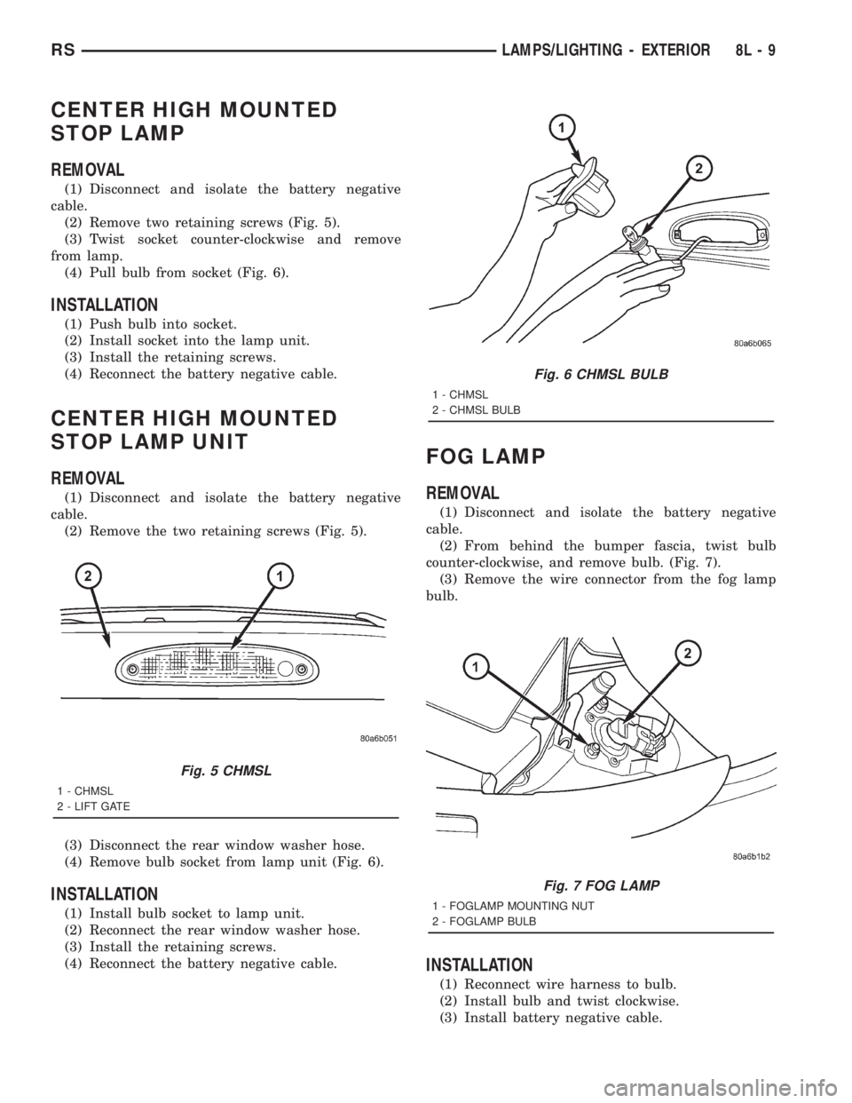
(2) Remove two retaining screws (Fig. 5).
(3) Twist socket counter-clockwise and remove
from lamp.
(4) Pull bulb from socket (Fig. 6).
INSTALLATION
(1) Push bulb into socket.
(2) Install socket into the lamp unit.
(3) Install the retaining screws.
(4) Reconnect the battery negative cable.
CENTER HIGH MOUNTED
STOP LAMP UNIT
REMOVAL
(1) Disconnect and isolate the battery negative
cable.
(2) Remove the two retaining screws (Fig. 5).
(3) Disconnect the rear window washer hose.
(4) Remove bulb socket from lamp unit (Fig. 6).
INSTALLATION
(1) Install bulb socket to lamp unit.
(2) Reconnect the rear window washer hose.
(3) Install the retaining screws.
(4) Reconnect the battery negative cable.
FOG LAMP
REMOVAL
(1) Disconnect and isolate the battery negative
cable.
(2) From behind the bumper fascia, twist bulb
counter-clockwise, and remove bulb. (Fig. 7).
(3) Remove the wire connector from the fog lamp
bulb.
INSTALLATION
(1) Reconnect wire harness to bulb.
(2) Install bulb and twist clockwise.
(3) Install battery negative cable.
Fig. 5 CHMSL
1 - CHMSL
2 - LIFT GATE
Fig. 6 CHMSL BULB
1 - CHMSL
2 - CHMSL BULB
Fig. 7 FOG LAMP
1 - FOGLAMP MOUNTING NUT
2 - FOGLAMP BULB
RSLAMPS/LIGHTING - EXTERIOR8L-9
Page 1981 of 4284
POWER SYSTEMS
TABLE OF CONTENTS
page page
POWER LIFTGATE SYSTEM.................. 1
POWER SLIDING DOOR SYSTEM............ 19
POWER LOCKS........................... 39POWER MIRRORS........................ 45
POWER SEATS........................... 49
POWER WINDOWS........................ 60
POWER LIFTGATE SYSTEM
TABLE OF CONTENTS
page page
POWER LIFTGATE SYSTEM
DESCRIPTION............................2
OPERATION.............................3
DIAGNOSIS AND TESTING..................4
DIAGNOSIS AND TESTING - POWER
LIFTGATE SYSTEM......................4
STANDARD PROCEDURE...................9
LIFTGATE ADJUSTMENT..................9
POWER LIFTGATE LEARN CYCLE..........9
PINCH SENSOR
DESCRIPTION............................9
OPERATION.............................9
REMOVAL...............................9
INSTALLATION...........................10
FULL OPEN SWITCH
DESCRIPTION...........................10
OPERATION.............................10
REMOVAL..............................10
INSTALLATION...........................10
LIFTGATE MOTOR
DESCRIPTION...........................11
OPERATION.............................11
REMOVAL..............................11
INSTALLATION...........................11
ENGAGE ACTUATOR
DESCRIPTION...........................12
OPERATION.............................12
REMOVAL..............................12
INSTALLATION...........................12TRANSVERSE BRACKET
DESCRIPTION...........................13
OPERATION.............................13
REMOVAL..............................13
INSTALLATION...........................13
LIFT GEAR & LINK ROD
DESCRIPTION...........................14
OPERATION.............................14
REMOVAL..............................14
INSTALLATION...........................14
LATCH
DESCRIPTION...........................15
OPERATION.............................15
REMOVAL..............................15
INSTALLATION...........................15
LATCH ACTUATOR
DESCRIPTION...........................16
OPERATION.............................16
REMOVAL..............................16
INSTALLATION...........................16
EXTERIOR HANDLE SWITCH
DESCRIPTION...........................17
OPERATION.............................17
REMOVAL..............................17
INSTALLATION...........................17
CHIME/THERMISTOR
DESCRIPTION...........................18
OPERATION.............................18
REMOVAL..............................18
INSTALLATION...........................18
RSPOWER SYSTEMS8N-1
Page 1991 of 4284
(6) Verify power liftgate system and full open
switch operation. Cycle the power liftgate through
one complete open and close cycle, this will allow the
power liftgate control module to relearn its cycle with
the new components.
LIFTGATE MOTOR
DESCRIPTION
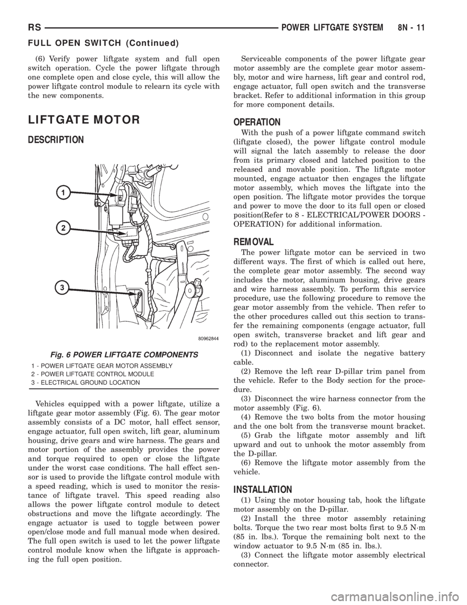
Vehicles equipped with a power liftgate, utilize a
liftgate gear motor assembly (Fig. 6). The gear motor
assembly consists of a DC motor, hall effect sensor,
engage actuator, full open switch, lift gear, aluminum
housing, drive gears and wire harness. The gears and
motor portion of the assembly provides the power
and torque required to open or close the liftgate
under the worst case conditions. The hall effect sen-
sor is used to provide the liftgate control module with
a speed reading, which is used to monitor the resis-
tance of liftgate travel. This speed reading also
allows the power liftgate control module to detect
obstructions and move the liftgate accordingly. The
engage actuator is used to toggle between power
open/close mode and full manual mode when desired.
The full open switch is used to let the power liftgate
control module know when the liftgate is approach-
ing the full open position.Serviceable components of the power liftgate gear
motor assembly are the complete gear motor assem-
bly, motor and wire harness, lift gear and control rod,
engage actuator, full open switch and the transverse
bracket. Refer to additional information in this group
for more component details.
OPERATION
With the push of a power liftgate command switch
(liftgate closed), the power liftgate control module
will signal the latch assembly to release the door
from its primary closed and latched position to the
released and movable position. The liftgate motor
mounted, engage actuator then engages the liftgate
motor assembly, which moves the liftgate into the
open position. The liftgate motor provides the torque
and power to move the door to its full open or closed
position(Refer to 8 - ELECTRICAL/POWER DOORS -
OPERATION) for additional information.
REMOVAL
The power liftgate motor can be serviced in two
different ways. The first of which is called out here,
the complete gear motor assembly. The second way
includes the motor, aluminum housing, drive gears
and wire harness assembly. To perform this service
procedure, use the following procedure to remove the
gear motor assembly from the vehicle. Then refer to
the other procedures called out this section to trans-
fer the remaining components (engage actuator, full
open switch, transverse bracket and lift gear and
rod) to the replacement motor assembly.
(1) Disconnect and isolate the negative battery
cable.
(2) Remove the left rear D-pillar trim panel from
the vehicle. Refer to the Body section for the proce-
dure.
(3) Disconnect the wire harness connector from the
motor assembly (Fig. 6).
(4) Remove the two bolts from the motor housing
and the one bolt from the transverse mount bracket.
(5) Grab the liftgate motor assembly and lift
upward and out to unhook the motor assembly from
the D-pillar.
(6) Remove the liftgate motor assembly from the
vehicle.
INSTALLATION
(1) Using the motor housing tab, hook the liftgate
motor assembly on the D-pillar.
(2) Install the three motor assembly retaining
bolts. Torque the two rear most bolts first to 9.5 N´m
(85 in. lbs.). Torque the remaining bolt next to the
window actuator to 9.5 N´m (85 in. lbs.).
(3) Connect the liftgate motor assembly electrical
connector.
Fig. 6 POWER LIFTGATE COMPONENTS
1 - POWER LIFTGATE GEAR MOTOR ASSEMBLY
2 - POWER LIFTGATE CONTROL MODULE
3 - ELECTRICAL GROUND LOCATION
RSPOWER LIFTGATE SYSTEM8N-11
FULL OPEN SWITCH (Continued)