window CHRYSLER VOYAGER 2001 Workshop Manual
[x] Cancel search | Manufacturer: CHRYSLER, Model Year: 2001, Model line: VOYAGER, Model: CHRYSLER VOYAGER 2001Pages: 4284, PDF Size: 83.53 MB
Page 1993 of 4284
(4) Install the left rear D-pillar trim on the vehi-
cle. Refer to Body for the procedure.
(5) Connect the negative battery cable.
(6) Using an appropriate scan tool, check and
erase any power liftgate control module diagnostic
trouble codes.
(7) Verify power liftgate system and engage actua-
tor operation. Cycle the power liftgate through one
complete open and close cycle.
TRANSVERSE BRACKET
DESCRIPTION
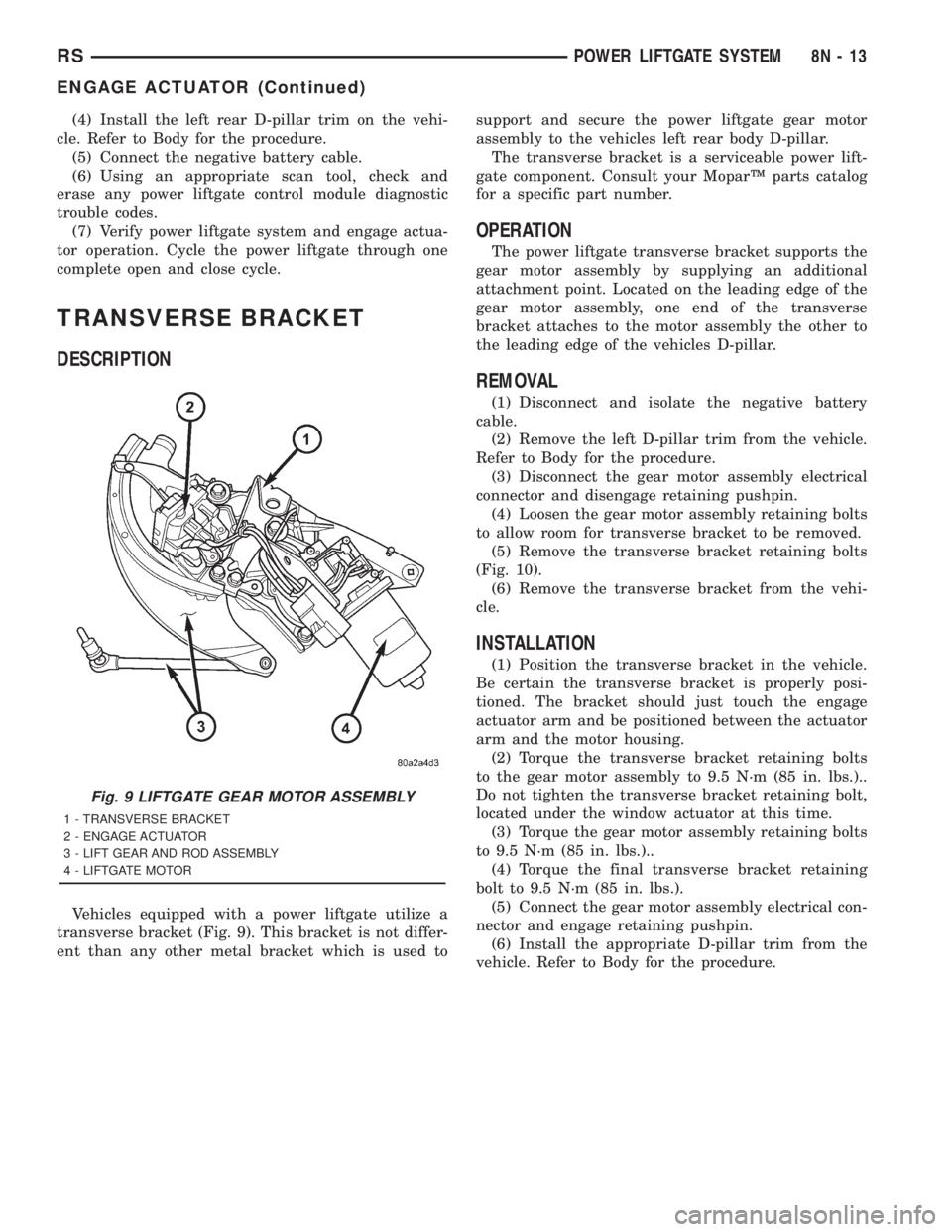
Vehicles equipped with a power liftgate utilize a
transverse bracket (Fig. 9). This bracket is not differ-
ent than any other metal bracket which is used tosupport and secure the power liftgate gear motor
assembly to the vehicles left rear body D-pillar.
The transverse bracket is a serviceable power lift-
gate component. Consult your MoparŸ parts catalog
for a specific part number.
OPERATION
The power liftgate transverse bracket supports the
gear motor assembly by supplying an additional
attachment point. Located on the leading edge of the
gear motor assembly, one end of the transverse
bracket attaches to the motor assembly the other to
the leading edge of the vehicles D-pillar.
REMOVAL
(1) Disconnect and isolate the negative battery
cable.
(2) Remove the left D-pillar trim from the vehicle.
Refer to Body for the procedure.
(3) Disconnect the gear motor assembly electrical
connector and disengage retaining pushpin.
(4) Loosen the gear motor assembly retaining bolts
to allow room for transverse bracket to be removed.
(5) Remove the transverse bracket retaining bolts
(Fig. 10).
(6) Remove the transverse bracket from the vehi-
cle.
INSTALLATION
(1) Position the transverse bracket in the vehicle.
Be certain the transverse bracket is properly posi-
tioned. The bracket should just touch the engage
actuator arm and be positioned between the actuator
arm and the motor housing.
(2) Torque the transverse bracket retaining bolts
to the gear motor assembly to 9.5 N´m (85 in. lbs.)..
Do not tighten the transverse bracket retaining bolt,
located under the window actuator at this time.
(3) Torque the gear motor assembly retaining bolts
to 9.5 N´m (85 in. lbs.)..
(4) Torque the final transverse bracket retaining
bolt to 9.5 N´m (85 in. lbs.).
(5) Connect the gear motor assembly electrical con-
nector and engage retaining pushpin.
(6) Install the appropriate D-pillar trim from the
vehicle. Refer to Body for the procedure.
Fig. 9 LIFTGATE GEAR MOTOR ASSEMBLY
1 - TRANSVERSE BRACKET
2 - ENGAGE ACTUATOR
3 - LIFT GEAR AND ROD ASSEMBLY
4 - LIFTGATE MOTOR
RSPOWER LIFTGATE SYSTEM8N-13
ENGAGE ACTUATOR (Continued)
Page 2001 of 4284

NOTE: It may be possible to generate Sliding Door
Diagnostic Trouble Codes during normal power
sliding door operation. Refer to the Body Diagnos-
tic Manual for a complete list of diagnostic routines.
For additional information, (Refer to 8 - ELECTRI-
CAL/POWER DOORS - OPERATION) . For a com-
plete power sliding door system wiring schematic,
refer to Wiring Diagrams. For power sliding door sys-
tem operation instructions, refer to the vehicle owner
manual.
WARNING: BE CERTAIN TO READ ALL WARNINGS
AND CAUTIONS IN POWER SLIDING DOOR OPER-
ATION BEFORE ATTEMPTING ANY SERVICE OF
POWER SLIDING DOOR SYSTEM OR COMPO-
NENTS.
OPERATION
With the push of a power sliding door open/close
command switch (key fob, overhead console or B-pil-
lar mounted) a signal is sent out to the Body Control
Module (BCM). The BCM then sends a signal out on
the PCI Data Bus circuit (J1850) to the power sliding
door module. The power sliding door module then
signals the power sliding door latch to release the
door to the unlatched and movable position. The
motor then starts an open cycle.
During the door open cycle, if the power sliding
door module detects sufficient resistance to door
travel, such as an obstruction in the door's path, the
power sliding door module will immediately stop door
movement and reverse door travel to the full open orclosed position. The ability for the power sliding door
module to detect resistance to door travel is accom-
plished by hall effect sensors and the door motor
speed.
The power sliding door control module has the abil-
ity to learn. Anytime a door is opened or closed using
the power sliding door system the module learns
from its cycle. If a replacement power sliding door
component is installed or a door adjustment is made,
the module must re-learn the effort required to open
or close the door. A learn cycle can be performed with
a Diagnostic Scan Tool, such as the DRB IIIt, or with
a complete cycle of the door, using any one of the
command switches. Refer to Standard Procedures in
this section for detailed instructions.
The power sliding door system is designed with a
number of system inhibitors. These inhibitors are
necessary for safety and/or feasibility of the power
sliding door system. See the power sliding door sys-
tem inhibitors noted below:
POWER SLIDING DOOR SYSTEM INHIBITORS
²The power sliding door must be in thefullopen
or closed position in order for the power sliding door
system to start a cycle. If the door is not in this posi-
tion (based on the input from the full open, pawl or
ratchet switches) the door control module will not
respond to command switch inputs.
²The vehicles transmission must be inpark or
neutralin order for the power sliding door system to
start a cycle.
²The vehicles child lockout switch must be in the
ªUNLOCKEDº position in order for the power sliding
door systems B-pillar switches to function.
²If multiple obstacles are detected during the
same power open or close cycle the power sliding
door may go into full manual mode.
²If severe Diagnostic Trouble Codes (DTC) are
stored in the power sliding door control module the
power sliding door may go into full manual mode.
²Due to the high pressure created in the passen-
ger compartment with the blower motor on high, the
power sliding door may not complete a power close
cycle unless a window is cracked, allowing the pres-
sure to escape. This situation will only be experi-
enced on some vehicles, or vehicles with brand new
side door weather seals installed. Refer to the Side
Door Adjustment procedure in the Standard Proce-
dures section of this group.
²The vehicles fuel tank filler door must be in the
closed position. Due to the sliding door interference
with the open fuel tank filler door, mechanical link-
age prevents the side door from opening and striking
the fuel door. Refer to the Body section of this man-
ual for detailed information on the fuel door lockout
feature.Fig. 3 POWER SIDE DOOR FUSE LOCATION
RSPOWER SLIDING DOOR SYSTEM8N-21
POWER SLIDING DOOR SYSTEM (Continued)
Page 2026 of 4284
AUTOMATIC DAY / NIGHT
MIRROR
DESCRIPTION
An automatic dimming inside day/night rear view
mirror and an automatic dimming driver side outside
rear view mirror are available factory-installed
options on this model. Following is a general descrip-
tion of this optional equipment.
The automatic day/night mirror is able to automat-
ically change its reflectance. A thin layer of electro-
chromic material between two pieces of conductive
glass make up the face of the mirror. Two photocell
sensors are used to monitor light levels and adjust
the reflectance of the mirror to reduce the glare of
headlamps approaching the vehicle from the rear.
For removal procedures, (Refer to 23 - BODY/IN-
TERIOR/REAR VIEW MIRROR - REMOVAL).
OPERATION
The ambient photocell sensor faces forward, to
detect the outside light levels. A second sensor facesrearward to detect the light level received through
the vehicles back window. When the difference
between the two light levels becomes too great (the
light level received at the rear of the mirror is much
higher than that at the front of the mirror), the mir-
ror begins to darken.
The mirror switch allows the driver a manual con-
trol of whether the automatic dimming feature is
operational. When AUTO is selected a small Light-
Emitting Diode (LED), to the right of the mirror
switch, is illuminated. The automatic dimming fea-
ture will only operate when the ignition switch is in
the On position. The mirror also senses the backup
lamp circuit, and will automatically disable its self-
dimming feature whenever the transmission gear
selector is in the Reverse position.
NOTE: The mirror always defaults to an ON state
upon ignition.
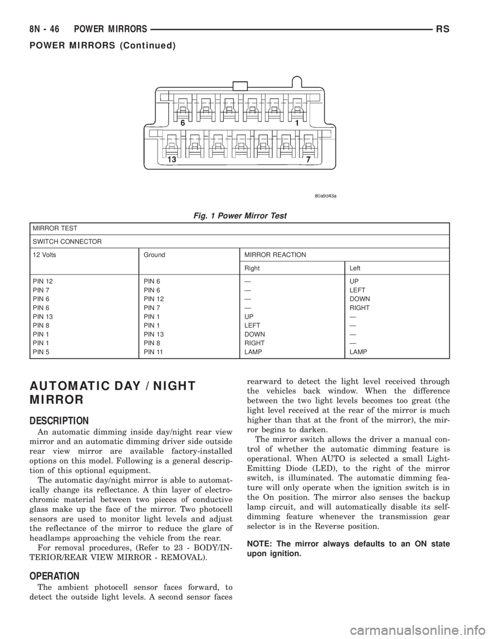
Fig. 1 Power Mirror Test
MIRROR TEST
SWITCH CONNECTOR
12 Volts Ground MIRROR REACTION
Right Left
PIN 12 PIN 6 Ð UP
PIN 7 PIN 6 Ð LEFT
PIN 6 PIN 12 Ð DOWN
PIN 6 PIN 7 Ð RIGHT
PIN 13 PIN 1 UP Ð
PIN 8 PIN 1 LEFT Ð
PIN 1 PIN 13 DOWN Ð
PIN 1 PIN 8 RIGHT Ð
PIN 5 PIN 11 LAMP LAMP
8N - 46 POWER MIRRORSRS
POWER MIRRORS (Continued)
Page 2040 of 4284
POWER WINDOWS
TABLE OF CONTENTS
page page
POWER WINDOWS
DESCRIPTION...........................60
OPERATION.............................60
DIAGNOSIS AND TESTING.................60
POWER WINDOWS.....................60
VENT WINDOW MOTOR
DIAGNOSIS AND TESTING.................61
VENT WINDOW MOTOR.................61
REMOVAL..............................61INSTALLATION...........................62
WINDOW MOTOR
REMOVAL..............................62
WINDOW SWITCH
DIAGNOSIS AND TESTING.................62
WINDOW SWITCH......................62
REMOVAL..............................63
INSTALLATION...........................63
POWER WINDOWS
DESCRIPTION
The Power Window System is activated through
switches mounted on the driver and passenger door
panels.
OPERATION
Front door window lift motors use permanent type
magnets. The B+ and ground applied at the motor ter-
minal pins will cause the motor to rotate in one direc-
tion. Reversing current through the motor terminals
will cause the motor to rotate in the opposite direction.
The power window motors ground through the
master switch in the driver door by a black wire
attached to the left cowl panel. Refer to the appropri-
ate wiring information. The wiring information
includes wiring diagrams, proper wire and connector
repair procedures, details of wire harness routing
and retention, connector pin-out information and
location views for the various wire harness connec-
tors, splices and grounds.
The power rear vent windows, if equipped, are oper-
ated by switches mounted in the driver door switch
bezel. A separate switch is used for each window. Per-
manent magnet type motors connected to a crank sys-
tem are used to open and close the rear vent windows.
A battery positive and negative connection to either of
the two motor terminals will cause the motor to rotate
in one direction. Reversing current through these same
two connections will cause the motor to rotate in the
opposite direction. Refer to the appropriate wiring infor-
mation. The wiring information includes wiring dia-
grams, proper wire and connector repair procedures,
details of wire harness routing and retention, connector
pin-out information and location views for the various
wire harness connectors, splices and grounds.
DIAGNOSIS AND TESTING - POWER
WINDOWS
POWER WINDOW MOTOR TEST
If the power window motor is receiving proper cur-
rent and ground and does not operate, proceed with
motor test. Refer to the appropriate wiring informa-
tion. The wiring information includes wiring dia-
grams, proper wire and connector repair procedures,
details of wire harness routing and retention, connec-
tor pin-out information and location views for the
various wire harness connectors, splices and grounds.
(1) Remove front door trim panel and sound pad as
necessary to gain access to power window motor wire
connector, (Refer to 23 - BODY/DOOR - FRONT/
TRIM PANEL - REMOVAL).
(2) Disconnect power window motor wire connector
from door harness.
(3) Using two jumper wires, connect one to a bat-
tery (+) source and the other to a good ground (-).
(4) Connect the Negative (-) jumper probe to one of
the motor connector terminals.
(5) Momentarily touch the Positive (+) jumper
probe to the other motor connector terminal.
When positive probe is connected the motor should
rotate in one direction to either move window up or
down. If window is all the way up or down the motor
will grunt and the inner door panel will flex when
actuated in that one direction.
(6) Reverse jumper probes at the motor connector
terminals and window should now move in opposite
direction. If window does not move or grunt, replace
the motor.
If window moved completely up or down, reverse
the jumper probes and cycle window to the opposite
position to verify full operation.
If motor grunts and does not move, verify that reg-
ulator is not binding.
8N - 60 POWER WINDOWSRS
Page 2041 of 4284
WIRING VOLTAGE TEST
The following wiring test determines whether or
not voltage is continuous through the body harness
to switch.
(1) Remove the power window switch and bezel
assembly from the driver door. (Refer to 8 - ELEC-
TRICAL/POWER WINDOWS/POWER WINDOW
SWITCH - REMOVAL).
(2) Disconnect wire connector from back of power
window switch.
(3) Switch ignition ON position.
(4) Connect the clip end of a 12 volt test light to
Pin 13 in door harness connector at the window
switch. Touch the test light probe to Pin 9 and then
to Pin 11.
²If the test light illuminates, the wiring circuit
between the battery and switch is OK.
²If the lamp does not illuminate, first check the
25 amp circuit breaker attached to the electrical dis-
tribution wiring bracket. If the circuit breaker is OK,
then check the 40 amp fuse (#28) in the Intelligent
Power Module. If both components are OK, then
check for a broken wire.
²Refer to the appropriate wiring information.
The wiring information includes wiring diagrams,
proper wire and connector repair procedures, details
of wire harness routing and retention, connector pin-
out information and location views for the various
wire harness connectors, splices and grounds.
VENT WINDOW MOTOR
DIAGNOSIS AND TESTING - VENT WINDOW
MOTOR
If the power vent window motor is receiving proper
current and ground and does not operate proceed
with motor test. Refer to the appropriate wiring
information. The wiring information includes wiring
diagrams, proper wire and connector repair proce-
dures, details of wire harness routing and retention,
connector pin-out information and location views for
the various wire harness connectors, splices and
grounds.
(1) Remove D-pillar trim panel necessary to gain
access to power vent window motor wire connector,
(Refer to 23 - BODY/INTERIOR/LEFT D-PILLAR
TRIM PANEL - REMOVAL) or (Refer to 23 - BODY/
INTERIOR/RIGHT D-PILLAR TRIM PANEL -
REMOVAL).
(2) Disconnect power vent window motor wire con-
nector from body harness.
(3) Using two jumper wires, connect one to a bat-
tery (+) source and the other to a good ground (-).
(4) Connect the Negative (-) jumper probe to one of
the motor connector terminals.(5) Momentarily touch the Positive (+) jumper
probe to the other motor connector terminal.
When positive probe is connected the motor should
rotate in one direction to either move window open or
closed. If window is all the way open or closed the
motor will grunt and the crank system will flex when
actuated in that one direction.
Reverse jumper probes at the motor connector ter-
minals and window should now move in opposite
direction. If window does not move or grunt, replace
the motor.
If window moved completely open or closed, reverse
the jumper probes and cycle window to the opposite
position to verify full operation.
If motor grunts and does not move, verify that
crank system is not binding.
REMOVAL
(1) Disconnect and isolate the battery negative
cable.
(2) Remove D-pillar trim panel. (Refer to 23 -
BODY/INTERIOR/LEFT D-PILLAR TRIM PANEL -
REMOVAL) or (Refer to 23 - BODY/INTERIOR/
RIGHT D-PILLAR TRIM PANEL - REMOVAL).
(3) Disconnect wire connector from power vent
motor.
(4) Using a flat bladed tool, carefully lift the circu-
lar actuator link tab. Remove link from window ball
socket.
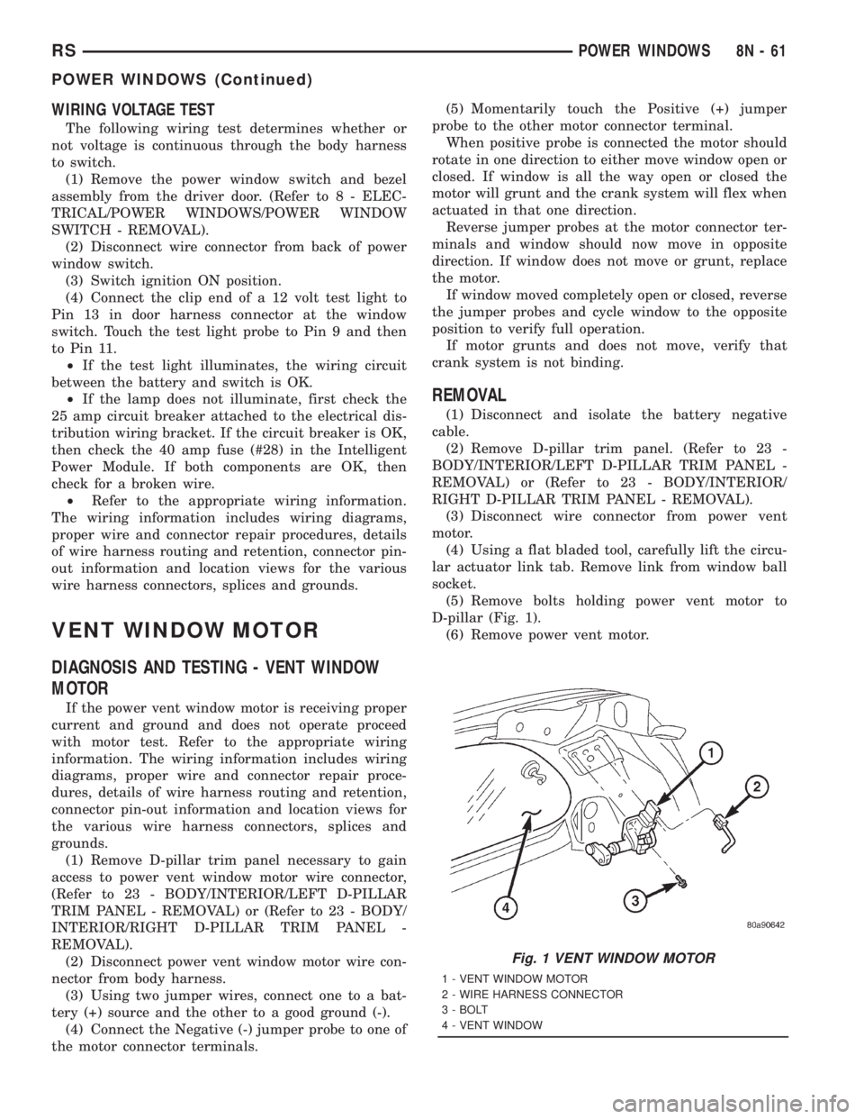
(5) Remove bolts holding power vent motor to
D-pillar (Fig. 1).
(6) Remove power vent motor.
Fig. 1 VENT WINDOW MOTOR
1 - VENT WINDOW MOTOR
2 - WIRE HARNESS CONNECTOR
3 - BOLT
4 - VENT WINDOW
RSPOWER WINDOWS8N-61
POWER WINDOWS (Continued)
Page 2042 of 4284
INSTALLATION
(1) Obtain new vent window motor.
(2) Snap the actuator link socket onto the quarter
window ball socket. Using a soft rubber mallet, push
the circular link tab flush with link surface.
(3) Install bolts holding power vent motor to D-pil-
lar.
(4) Reconnect wire connector to power vent motor.
(5) Reconnect the battery negative cable.
(6) Cycle quarter window open/close to verify func-
tion.
(7) Install D-pillar trim panel.
WINDOW MOTOR
REMOVAL
The window motor is incorporated into the window
regulator assembly. If the window motor requires
replacement, the window regulator must be replaced.
(Refer to 23 - BODY/DOOR - FRONT/WINDOW
REGULATOR - REMOVAL).
WINDOW SWITCH
DIAGNOSIS AND TESTING - WINDOW SWITCH
(1) Remove the desired switch to be tested from
the door trim panel. Driver's side (master) or passen-
ger side. (Refer to 8 - ELECTRICAL/POWER WIN-
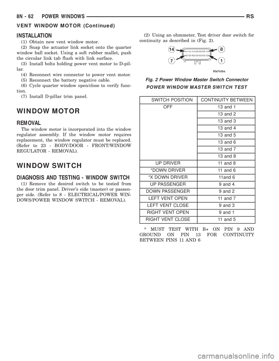
DOWS/POWER WINDOW SWITCH - REMOVAL).(2) Using an ohmmeter, Test driver door switch for
continuity as described in (Fig. 2).
POWER WINDOW MASTER SWITCH TEST
SWITCH POSITION CONTINUITY BETWEEN
OFF 13 and 1
13 and 2
13 and 3
13 and 4
13 and 5
13 and 6
13 and 7
13 and 8
UP DRIVER 11 and 8
*DOWN DRIVER 11 and 6
*X DOWN DRIVER 11and 6
UP PASSENGER 9 and 4
DOWN PASSENGER 9 and 2
LEFT VENT OPEN 11 and 7
LEFT VENT CLOSE 9 and 3
RIGHT VENT OPEN 9 and 1
RIGHT VENT CLOSE 11 and 5
* MUST TEST WITH B+ ON PIN 9 AND
GROUND ON PIN 13 FOR CONTINUITY
BETWEEN PINS 11 AND 6
Fig. 2 Power Window Master Switch Connector
8N - 62 POWER WINDOWSRS
VENT WINDOW MOTOR (Continued)
Page 2043 of 4284

(3) If the result are not OK, replace the driver side
window lift switch.
(4) Test passenger door switch for continuity as
described in (Fig. 3).
(5) If the results are not OK, replace the switch.
The power window master switch has a Auto-Down
feature. The switch is equipped with two detent posi-
tions when actuating the power window OPEN. The
first detent position allows the window to roll down
and stop when the switch is released. The second
detent position actuates an integral express roll
down relay that rolls the window down after the
switch is released. When the express down circuit
senses stall current (window has reached end of
down travel), the switch will turn current off to the
motor. The AUTO feature can be cancelled by actuat-
ing the switch UP or DOWN while window is in
motion. If the electronic circuit in the switch fails todetect a stall current, the auto down circuit will time
out within 9 to 13 seconds.
REMOVAL
(1) Disconnect and isolate the battery negative
cable.
(2) Using a trim stick, start at the bottom of the
switch and bezel assembly and pry up to remove the
switch and bezel assembly from the door trim panel
(Fig. 4).
(3) Unlatch the locking tab on the harness side
connector of the switch.
(4) Disconnect wire harness connectors from
switch.
INSTALLATION
(1) Reconnect wire harness connector to switch.
(2) Insert switch into door trim panel and press
into place.
(3) Reconnect battery negative cable.
Fig. 3 Passenger Door Power Window Switch
SWITCH POSITION CONTINUITY BETWEEN
OFF 3 AND 8
OFF 2 AND 5
UP 1 AND 8
DOWN 1 AND 5
Fig. 4 POWER WINDOW SWITCH
1 - DOOR TRIM PANEL
2 - POWER WINDOW SWITCH AND BEZEL ASSEMBLY
RSPOWER WINDOWS8N-63
WINDOW SWITCH (Continued)
Page 2076 of 4284

The windshield wiper motor and linkage is located
in an integral wiper unit at the rear of the engine
compartment. The wiper unit must be removed to
gain access to the wiper motor.
REAR WIPER/WASHER SYSTEM
When continuous rear wiper operation is required,
the Body Control Module (BCM) will provide ignition
ON voltage to the rear wiper motor. When the wiper
switch is turned OFF, the BCM provides circuit
ground to operate the motor until the wipe cycle is
complete and the wiper arm returns to the base of
the rear window.
When intermittent rear wiper mode is selected, the
wiper motor will cycle every 7 seconds. The intermit-
tent delay time is also adjusted based upon vehicle
speed. With the vehicle traveling greater at 50 mph,
the cycle changes to every 5 seconds. DIAGNOSIS
AND TESTING
DIAGNOSIS AND TESTING - FRONT WIPER
SYSTEM
The windshield wiper system operates in several
modes:
²Low and high speed normal wipe
²Speed sensitive intermittent wipe
²Wipe after wash
²Pulse wipe
²Park (switch OFF)
The windshield wiper circuits are continuously
monitored and controlled by the Body Control Mod-
ule (BCM). If a problem occurs in the electronic com-
ponents, wiring, switch (except integral motor park
switch) and wiper motor a Diagnostic Trouble Code
(DTC) will be stored in the BCM memory. DTC's can
be retrieved using a DRB IIItscan tool. Refer to the
proper Body Diagnostic Procedures manual for DTC
descriptions and retrieval information.
The windshield wiper park switch and circuit is
monitored by the BCM. The park switch and circuit
can be tested using the Wiper System Diagnosis
table.
DIAGNOSIS AND TESTING - REAR WIPER
SYSTEM
The rear window wiper system operates in several
modes:
²Continuous wipe
²Intermittent wipe
²Wash
²Wipe after wash
The windshield wiper circuits are continuously
monitored and controlled by the Body Control Mod-
ule (BCM). If a problem occurs in the electronic com-
ponents, wiring, switch (except integral motor parkswitch) and wiper motor a Diagnostic Trouble Code
(DTC) will be stored in the BCM memory. The
DTC(s) can be retrieved using a DRB IIItscan tool.
DIAGNOSIS AND TESTING - FRONT
WIPER/WASHER SWITCH
To test the front wiper/washer portion of the multi-
function switch:
(1) Remove the multi-function switch (Refer to 8 -
ELECTRICAL/LAMPS/LIGHTING - EXTERIOR/
MULTI-FUNCTION SWITCH - REMOVAL).
(2) Using an ohmmeter check continuity reading
between switch pins. See (Fig. 1) and the table.
WIPER/WASHER SWITCH CONTINUITY
SWITCH POSITION RESISTANCE VALUE
BETWEEN
OFF 6 AND 7 = OPEN CIRCUIT
DELAY POSITION
1ST 6AND7=8KV680V
2ND 6AND7=6KV660V
3RD 6 AND 7 = 4.5 KV645V
4TH 6 AND 7 = 3.5 KV635V
5TH 6 AND 7 = 2.5 KV625V
6TH 6 AND 7 = 1.5 KV615V
LOW 6AND7=1KV610V
HIGH 6 AND7=1KV610V
WASH 6 AND 11 = CONTINUITY
DIAGNOSIS AND TESTING - FAILED PARK
SWITCH
If the wiper park switch has failed the windshield
wipers will operate as follows:
²SWITCH OFF- Wipers stop in current location
regardless of the park signal.
²INTERMITTENT MODE- Wipers operate at
low speed for one or more extra wipes or continu-
ously.
Fig. 1 WIPER/WASHER SWITCH PIN CALL OUT
8R - 2 WIPERS/WASHERSRS
WIPERS/WASHERS (Continued)
Page 2077 of 4284
²LOW SPEED- Wipers operate at low speed.
²HIGH SPEED- Wipers operate at high speed.
²PULSE WIPE- Wipers will not operate.
²WIPE AFTER WASH- Wipers operate at low
speed in any mode setting. Wipers operate only whilewash button is depressed with switch in OFF mode,
wipers stop in mid-cycle when button is released.
The windshield wiper park switch and circuit is
monitored by the BCM. The park switch and circuit
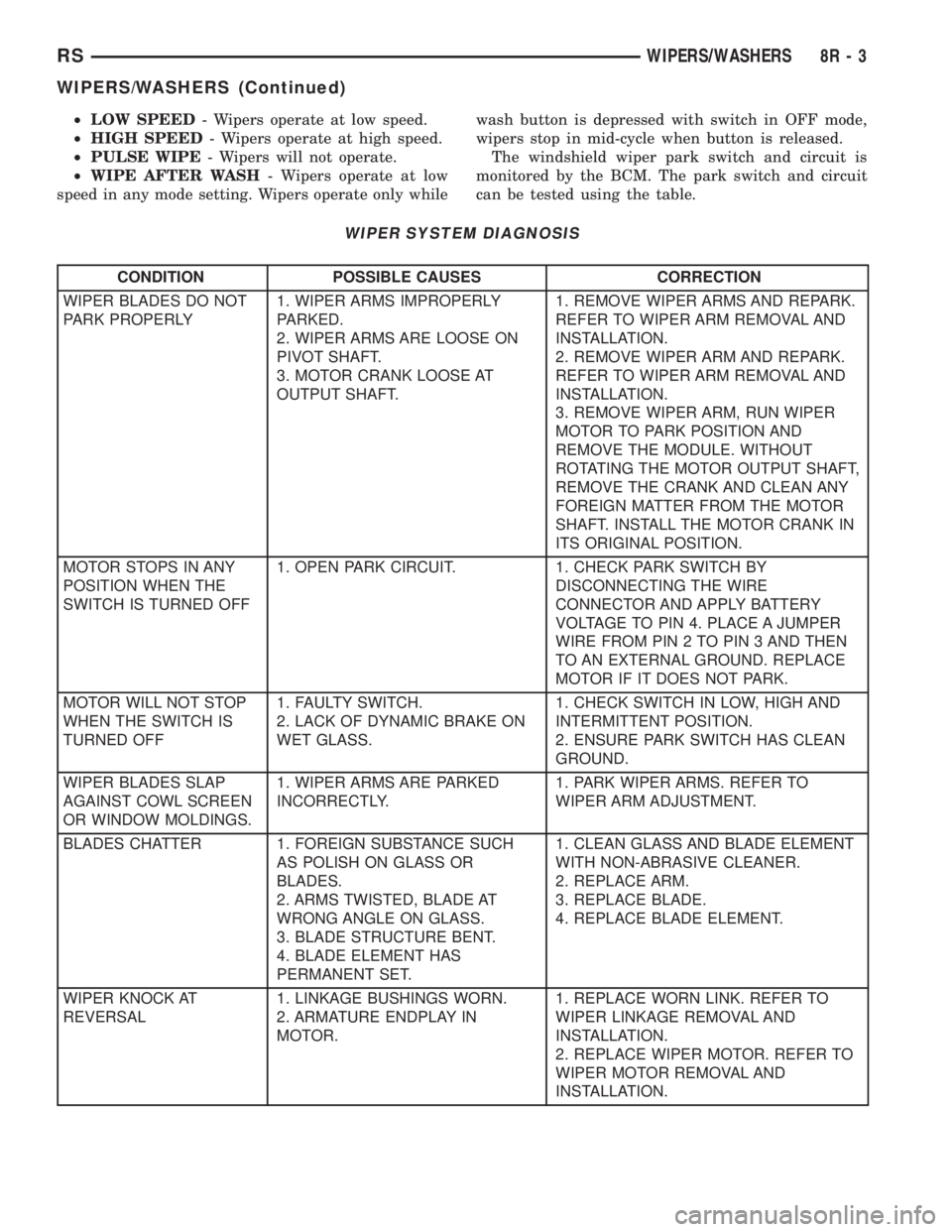
can be tested using the table.
WIPER SYSTEM DIAGNOSIS
CONDITION POSSIBLE CAUSES CORRECTION
WIPER BLADES DO NOT
PARK PROPERLY1. WIPER ARMS IMPROPERLY
PARKED.
2. WIPER ARMS ARE LOOSE ON
PIVOT SHAFT.
3. MOTOR CRANK LOOSE AT
OUTPUT SHAFT.1. REMOVE WIPER ARMS AND REPARK.
REFER TO WIPER ARM REMOVAL AND
INSTALLATION.
2. REMOVE WIPER ARM AND REPARK.
REFER TO WIPER ARM REMOVAL AND
INSTALLATION.
3. REMOVE WIPER ARM, RUN WIPER
MOTOR TO PARK POSITION AND
REMOVE THE MODULE. WITHOUT
ROTATING THE MOTOR OUTPUT SHAFT,
REMOVE THE CRANK AND CLEAN ANY
FOREIGN MATTER FROM THE MOTOR
SHAFT. INSTALL THE MOTOR CRANK IN
ITS ORIGINAL POSITION.
MOTOR STOPS IN ANY
POSITION WHEN THE
SWITCH IS TURNED OFF1. OPEN PARK CIRCUIT. 1. CHECK PARK SWITCH BY
DISCONNECTING THE WIRE
CONNECTOR AND APPLY BATTERY
VOLTAGE TO PIN 4. PLACE A JUMPER
WIRE FROM PIN 2 TO PIN 3 AND THEN
TO AN EXTERNAL GROUND. REPLACE
MOTOR IF IT DOES NOT PARK.
MOTOR WILL NOT STOP
WHEN THE SWITCH IS
TURNED OFF1. FAULTY SWITCH.
2. LACK OF DYNAMIC BRAKE ON
WET GLASS.1. CHECK SWITCH IN LOW, HIGH AND
INTERMITTENT POSITION.
2. ENSURE PARK SWITCH HAS CLEAN
GROUND.
WIPER BLADES SLAP
AGAINST COWL SCREEN
OR WINDOW MOLDINGS.1. WIPER ARMS ARE PARKED
INCORRECTLY.1. PARK WIPER ARMS. REFER TO
WIPER ARM ADJUSTMENT.
BLADES CHATTER 1. FOREIGN SUBSTANCE SUCH
AS POLISH ON GLASS OR
BLADES.
2. ARMS TWISTED, BLADE AT
WRONG ANGLE ON GLASS.
3. BLADE STRUCTURE BENT.
4. BLADE ELEMENT HAS
PERMANENT SET.1. CLEAN GLASS AND BLADE ELEMENT
WITH NON-ABRASIVE CLEANER.
2. REPLACE ARM.
3. REPLACE BLADE.
4. REPLACE BLADE ELEMENT.
WIPER KNOCK AT
REVERSAL1. LINKAGE BUSHINGS WORN.
2. ARMATURE ENDPLAY IN
MOTOR.1. REPLACE WORN LINK. REFER TO
WIPER LINKAGE REMOVAL AND
INSTALLATION.
2. REPLACE WIPER MOTOR. REFER TO
WIPER MOTOR REMOVAL AND
INSTALLATION.
RSWIPERS/WASHERS8R-3
WIPERS/WASHERS (Continued)
Page 2081 of 4284
INSTALLATION
(1) Position arm on pivot.
(2) Pull up on arm and release lock
(3) Allow wiper arm to rest on rear window.
REAR WIPER MOTOR
REMOVAL
(1) Disconnect and isolate the negative battery
cable.
(2) Remove rear wiper arm. (Refer to 8 - ELEC-
TRICAL/WIPERS/WASHERS/WIPER ARMS -
REMOVAL) in this section.
(3) Open liftgate.
(4) Remove liftgate trim panel. (Refer to 23 -
BODY/DECKLID/HATCH/LIFTGATE/TAILGATE/
TRIM PANEL - REMOVAL).
(5) Disconnect wire connector from rear wiper
motor.
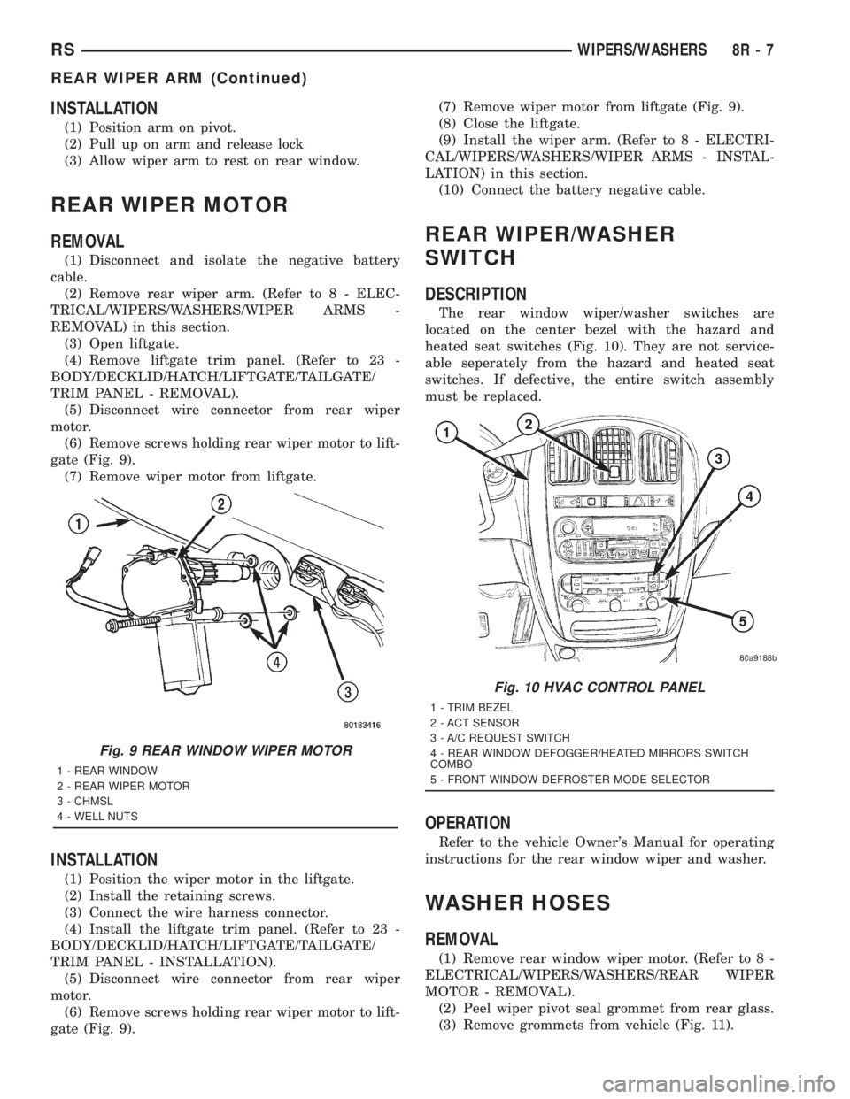
(6) Remove screws holding rear wiper motor to lift-
gate (Fig. 9).
(7) Remove wiper motor from liftgate.
INSTALLATION
(1) Position the wiper motor in the liftgate.
(2) Install the retaining screws.
(3) Connect the wire harness connector.
(4) Install the liftgate trim panel. (Refer to 23 -
BODY/DECKLID/HATCH/LIFTGATE/TAILGATE/
TRIM PANEL - INSTALLATION).
(5) Disconnect wire connector from rear wiper
motor.
(6) Remove screws holding rear wiper motor to lift-
gate (Fig. 9).(7) Remove wiper motor from liftgate (Fig. 9).
(8) Close the liftgate.
(9) Install the wiper arm. (Refer to 8 - ELECTRI-
CAL/WIPERS/WASHERS/WIPER ARMS - INSTAL-
LATION) in this section.
(10) Connect the battery negative cable.
REAR WIPER/WASHER
SWITCH
DESCRIPTION
The rear window wiper/washer switches are
located on the center bezel with the hazard and
heated seat switches (Fig. 10). They are not service-
able seperately from the hazard and heated seat
switches. If defective, the entire switch assembly
must be replaced.
OPERATION
Refer to the vehicle Owner's Manual for operating
instructions for the rear window wiper and washer.
WASHER HOSES
REMOVAL
(1) Remove rear window wiper motor. (Refer to 8 -
ELECTRICAL/WIPERS/WASHERS/REAR WIPER
MOTOR - REMOVAL).
(2) Peel wiper pivot seal grommet from rear glass.
(3) Remove grommets from vehicle (Fig. 11).
Fig. 9 REAR WINDOW WIPER MOTOR
1 - REAR WINDOW
2 - REAR WIPER MOTOR
3 - CHMSL
4 - WELL NUTS
Fig. 10 HVAC CONTROL PANEL
1 - TRIM BEZEL
2 - ACT SENSOR
3 - A/C REQUEST SWITCH
4 - REAR WINDOW DEFOGGER/HEATED MIRRORS SWITCH
COMBO
5 - FRONT WINDOW DEFROSTER MODE SELECTOR
RSWIPERS/WASHERS8R-7
REAR WIPER ARM (Continued)