window CHRYSLER VOYAGER 2001 User Guide
[x] Cancel search | Manufacturer: CHRYSLER, Model Year: 2001, Model line: VOYAGER, Model: CHRYSLER VOYAGER 2001Pages: 4284, PDF Size: 83.53 MB
Page 471 of 4284
Symptom:
EBL RUN ONLY RELAY SHORTED TO BATTERY
When Monitored and Set Condition:
EBL RUN ONLY RELAY SHORTED TO BATTERY
When Monitored: Continuously with the ignition on.
Set Condition: The FCM has detected a short to battery voltage in the Rear Defogger
Relay control circuit.
POSSIBLE CAUSES
VERIFY ACTIVE DTC
FRONT CONTROL MODULE
INTELLIGENT POWER MODULE
REAR WINDOW DEFOGGER RELAY
TEST ACTION APPLICABILITY
1 Turn the ignition on.
With the DRBIIIt, erase the current Front Control Module DTC's.
Turn the ignition off, wait 10 seconds then turn the ignition on.
With the DRBIIIt, read the current Front Control Module DTC's.
Does the DRBIIItdisplay EBL RUN ONLY RELAY SHORTED TO BATTERY
trouble code?All
Ye s®Go To 2
No®The condition that caused this symptom is currently not present
at this time.
Perform BODY VERIFICATION TEST - VER 1.
2 Turn the ignition off.
Install a known good relay in place of the Rear Window Defogger relay.
Turn the ignition on.
Attempt to operate the Rear Window Defogger.
With the DRBIIIt, read the current Front Control Module DTCs.
Did the DTC reset?All
Ye s®Go To 3
No®Replace the Rear Defogger Relay.
Perform BODY VERIFICATION TEST - VER 1.
3 Turn the ignition off.
Remove the Rear Window Defogger Relay from the IPM.
Remove the Front Control Module from the IPM.
Measure the voltage of the Rear Window Relay Control circuit.
Is the voltage above 1.0 volts?All
Ye s®Replace the Fuse and Relay Center.
Perform BODY VERIFICATION TEST - VER 1.
No®Replace the Front Control Module.
Perform BODY VERIFICATION TEST - VER 1.
442
ELECTRICALLY HEATED SYSTEMS
Page 541 of 4284

Symptom List:
A/C FAULT (ACTIVE) - MANUAL A/C
CHECKSUM FAILURE (ACTIVE) - MANUAL A/C
POWER FAULT (ACTIVE) - MANUAL A/C
REAR DEFOG FAILURE (ACTIVE) - MAN A/C
RECIRCULATION FAULT (ACTIVE) - MANUAL A/C
UNKNOWN FAULT DETECTED (ACTIVE) - MANUAL A/C
Test Note: All symptoms listed above are diagnosed using the same tests.
The title for the tests will be A/C FAULT (ACTIVE) - MANUAL
A/C.
When Monitored and Set Condition:
A/C FAULT (ACTIVE) - MANUAL A/C
When Monitored: With the ignition on.
Set Condition: This DTC will set if the A/C switch stays closed for 10 minutes.
CHECKSUM FAILURE (ACTIVE) - MANUAL A/C
When Monitored: With the ignition on.
Set Condition: This DTC will set if the calibrated check sum does not match the stored
value.
POWER FAULT (ACTIVE) - MANUAL A/C
When Monitored: With the ignition on.
Set Condition: This DTC will set if the Power switch stays closed for 10 minutes.
REAR DEFOG FAILURE (ACTIVE) - MAN A/C
When Monitored: With the ignition on.
Set Condition: This DTC will set if the Rear Window Defogger switch stays closed for 10
minutes.
RECIRCULATION FAULT (ACTIVE) - MANUAL A/C
When Monitored: With the ignition on.
Set Condition: This DTC will set if the Recirc switch stays closed for 10 minutes.
UNKNOWN FAULT DETECTED (ACTIVE) - MANUAL A/C
When Monitored: With the ignition on.
Set Condition: This DTC will set if the A/C - Heater Cotrol Module detects an internal
fault.
512
HEATING & A/C
Page 545 of 4284
NO BCM MESSAGE RECEIVED (STORED) - MANUAL A/C
When Monitored: With the igntion on.
Set Condition: If the A/C - Heater Control Module does not receive the dimming function
message from the BCM for more than 5 seconds, then the A/C - Heater Control Module
LEDs will default to full brightness and the DTC will set.
NO PCM MESSAGE RECEIVED (STORED) - MANUAL A/C
When Monitored: With the ignition on.
Set Condition: This DTC will set if the A/C - Heater Control Module does not see any
messages from the PCM for more than 5 seconds.
PCM COMMUNICATION FAILURE (STORED) - MANUAL A/C
When Monitored: With the ignition on.
Set Condition: This DTC will set if the A/C - Heater Control Module does not receive the
Fuel message from the PCM for more than 5 seconds.
POWER FAULT (STORED) - MANUAL A/C
When Monitored: With the ignition on.
Set Condition: This DTC will set if the Power switch stays closed for 10 minutes.
REAR BLEND OVERCURRENT (STORED) - MANUAL A/C
When Monitored: When actuator movement is requested.
Set Condition: All (Blend, Mode, Recirc, and Zone) Overcurrent DTCs will set if the A/C
- Heater Control Module detects an excessive current draw on the Common Door Drive
circuit(s).
REAR BLEND POT CIRCUIT OPEN (STORED) - MANUAL A/C
When Monitored: With the ignition on.
Set Condition: This DTC will set if the Rear Blower Rear Control Switch, Rear Blend
Potentiometer/circuit is open.
REAR BLEND POT CIRCUIT SHORT (STORED) - MANUAL A/C
When Monitored: When the ignition is on.
Set Condition: This DTC will set if the Rear Blower Rear Control Switch, Rear Blend
Potentiometer/5 Volt Supply/Rear Temperature Feedback Signal circuit is shorted low or
high.
REAR DEFOG FAILURE (STORED) - MANUAL A/C
When Monitored: With the ignition on.
Set Condition: This DTC will set if the Rear Window Defogger switch stays closed for 10
minutes.
516
HEATING & A/C
A/C FAULT (STORED) - MANUAL A/C ÐContinued
Page 547 of 4284

POSSIBLE CAUSES
CHECK FOR ACTIVE HVAC DTCS, & COOLDOWN TEST & DOOR RECALIBRATION MESSAGES
STORED CODE(S) TEST COMPLETE
TEST ACTION APPLICABILITY
1NOTE: Active codes must be resolved before diagnosing stored codes.
NOTE: Anytime a code becomes active during this test, proceed to the
conclusion question.
Turn the ignition on.
With the DRBIIIt, record and erase stored HVAC DTC's.
Cycle the ignition switch.
Start the engine.
Monitor the DRBIIItfor active HVAC DTCs while performing the following test
steps.
Manually press the A/C - Heater Control power switch on.
Turn the front blower motor control switch knob to the low position.
If equipped, turn the rear blower motor control switch knob to the low position.
Set the passenger blend control switch to the full cold position.
If equipped, set the zone/driver blend control switch to the full cold position.
Turn the mode select switch knob to the panel position.
Manually press the recirculation mode switch on, wait 30 seconds then press it off.
Manually press the A/C mode switch on, wait 30 seconds then press it off.
Manually press the rear window defogger switch on, wait 30 seconds then press it off.
Manually sweep the passenger blend control switch from full cold to full hot then
back to full cold.
If equipped, manually sweep the zone/driver blend control switch from full cold to full
hot then back to full cold.
Manually sweep the front blower motor control switch knob through all positions.
If equipped, manually sweep the rear blower motor control switch knob through all
positions.
If equipped, turn the rear blower motor control switch knob to the rear position.
If equipped, on the Rear Blower Rear Control, manually sweep the rear blower motor
control switch knob through all positions.
If equipped, on the Rear Blower Rear Control, manually sweep the rear blend/mode
control switch knob from full cold to full hot then back to full cold.
With the DRBIIIt, actuate the AC Cooldown Test.
With the DRBIIIt, actuate the HVAC Door Recalibration Test.
Place the vehicle on a hoist, and raise the wheels off the floor.
WARNING: Be sure to keep hands and feet clear of rotating wheels. Keep
clear of the engine's moving parts
Start the engine. Place the transmission in drive. Brake off.
Does the DRBIIItdisplay any active HVAC DTC(s), Cooldown Test or Door Recali-
bration message(s)?All
Ye s®Return to the symptom list and choose the symptom(s).
Perform BODY VERIFICATION TEST - VER 1.
No®No problem found at this time.
Perform BODY VERIFICATION TEST - VER 1.
518
HEATING & A/C
A/C FAULT (STORED) - MANUAL A/C ÐContinued
Page 1023 of 4284
VTSS VERIFICATION TEST - 1A APPLICABILITY
1. Ensure all doors, hood, and liftgate are closed.
2. Open the driver's door.
3. Remove the ignition key (but keep in hand).
4. Lower the driver door window and lock the doors with the RKE transmitter.
5. Close the driver's door.
6. Observe the VTSS Indicator.
7. The VTSS Indicator will flash rapidly for approximately 15 seconds and then begin to flash
slowly. If the VTSS Indicator is not performing as described, this indicates a system fault. Refer
to symptom list for problems related to THEFT ALARM WILL NOT ARM.
8. Perform a system test on the VTSS by duplicating the original complaint.
9. Disarm the system and with the DRBIIIt, read DTC's.
10. If the original complaint is corrected and there are no DTC's the repair is complete.
Are any DTC's present or is the original complaint still present?All
Ye s®Repair is not complete, refer to the appropriate symptom.
No®Repair is complete.
994
VERIFICATION TESTS
Verification Tests ÐContinued
Page 1066 of 4284
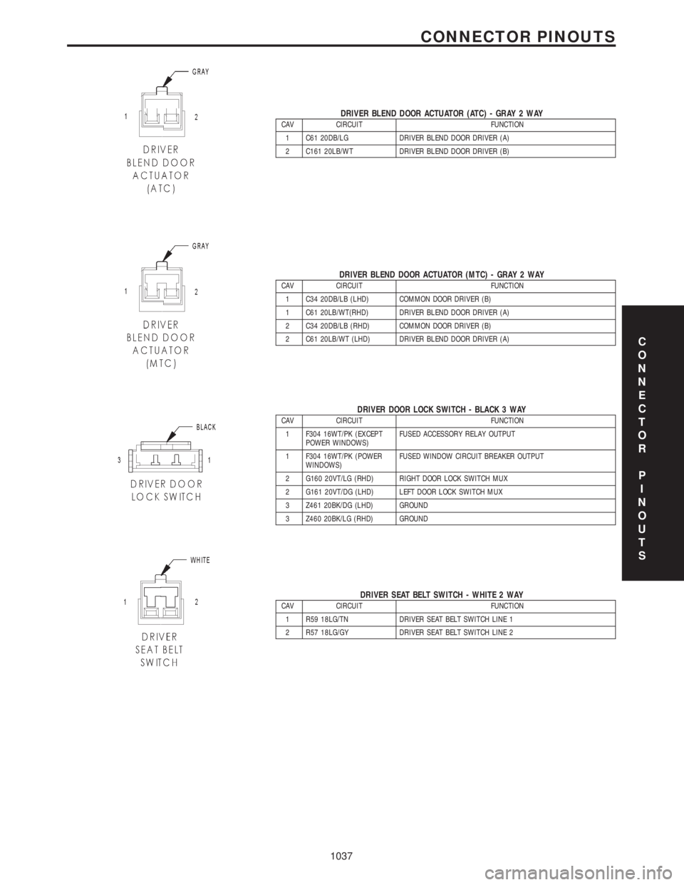
DRIVER BLEND DOOR ACTUATOR (ATC) - GRAY 2 WAYCAV CIRCUIT FUNCTION
1 C61 20DB/LG DRIVER BLEND DOOR DRIVER (A)
2 C161 20LB/WT DRIVER BLEND DOOR DRIVER (B)
DRIVER BLEND DOOR ACTUATOR (MTC) - GRAY 2 WAYCAV CIRCUIT FUNCTION
1 C34 20DB/LB (LHD) COMMON DOOR DRIVER (B)
1 C61 20LB/WT(RHD) DRIVER BLEND DOOR DRIVER (A)
2 C34 20DB/LB (RHD) COMMON DOOR DRIVER (B)
2 C61 20LB/WT (LHD) DRIVER BLEND DOOR DRIVER (A)
DRIVER DOOR LOCK SWITCH - BLACK 3 WAYCAV CIRCUIT FUNCTION
1 F304 16WT/PK (EXCEPT
POWER WINDOWS)FUSED ACCESSORY RELAY OUTPUT
1 F304 16WT/PK (POWER
WINDOWS)FUSED WINDOW CIRCUIT BREAKER OUTPUT
2 G160 20VT/LG (RHD) RIGHT DOOR LOCK SWITCH MUX
2 G161 20VT/DG (LHD) LEFT DOOR LOCK SWITCH MUX
3 Z461 20BK/DG (LHD) GROUND
3 Z460 20BK/LG (RHD) GROUND
DRIVER SEAT BELT SWITCH - WHITE 2 WAYCAV CIRCUIT FUNCTION
1 R59 18LG/TN DRIVER SEAT BELT SWITCH LINE 1
2 R57 18LG/GY DRIVER SEAT BELT SWITCH LINE 2
C
O
N
N
E
C
T
O
R
P
I
N
O
U
T
S
1037
CONNECTOR PINOUTS
Page 1076 of 4284
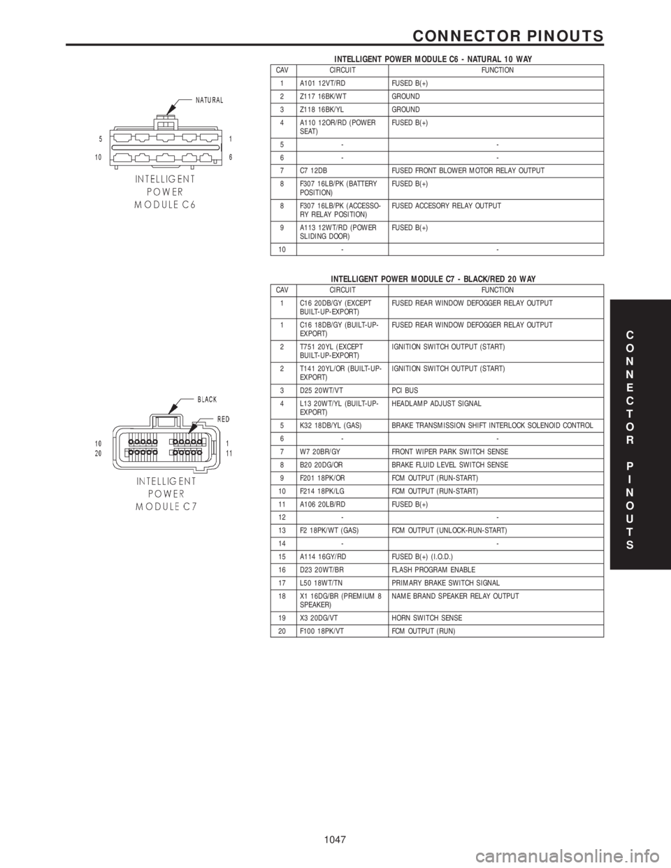
INTELLIGENT POWER MODULE C6 - NATURAL 10 WAYCAV CIRCUIT FUNCTION
1 A101 12VT/RD FUSED B(+)
2 Z117 16BK/WT GROUND
3 Z118 16BK/YL GROUND
4 A110 12OR/RD (POWER
SEAT)FUSED B(+)
5- -
6- -
7 C7 12DB FUSED FRONT BLOWER MOTOR RELAY OUTPUT
8 F307 16LB/PK (BATTERY
POSITION)FUSED B(+)
8 F307 16LB/PK (ACCESSO-
RY RELAY POSITION)FUSED ACCESORY RELAY OUTPUT
9 A113 12WT/RD (POWER
SLIDING DOOR)FUSED B(+)
10 - -
INTELLIGENT POWER MODULE C7 - BLACK/RED 20 WAYCAV CIRCUIT FUNCTION
1 C16 20DB/GY (EXCEPT
BUILT-UP-EXPORT)FUSED REAR WINDOW DEFOGGER RELAY OUTPUT
1 C16 18DB/GY (BUILT-UP-
EXPORT)FUSED REAR WINDOW DEFOGGER RELAY OUTPUT
2 T751 20YL (EXCEPT
BUILT-UP-EXPORT)IGNITION SWITCH OUTPUT (START)
2 T141 20YL/OR (BUILT-UP-
EXPORT)IGNITION SWITCH OUTPUT (START)
3 D25 20WT/VT PCI BUS
4 L13 20WT/YL (BUILT-UP-
EXPORT)HEADLAMP ADJUST SIGNAL
5 K32 18DB/YL (GAS) BRAKE TRANSMISSION SHIFT INTERLOCK SOLENOID CONTROL
6- -
7 W7 20BR/GY FRONT WIPER PARK SWITCH SENSE
8 B20 20DG/OR BRAKE FLUID LEVEL SWITCH SENSE
9 F201 18PK/OR FCM OUTPUT (RUN-START)
10 F214 18PK/LG FCM OUTPUT (RUN-START)
11 A106 20LB/RD FUSED B(+)
12 - -
13 F2 18PK/WT (GAS) FCM OUTPUT (UNLOCK-RUN-START)
14 - -
15 A114 16GY/RD FUSED B(+) (I.O.D.)
16 D23 20WT/BR FLASH PROGRAM ENABLE
17 L50 18WT/TN PRIMARY BRAKE SWITCH SIGNAL
18 X1 16DG/BR (PREMIUM 8
SPEAKER)NAME BRAND SPEAKER RELAY OUTPUT
19 X3 20DG/VT HORN SWITCH SENSE
20 F100 18PK/VT FCM OUTPUT (RUN)
C
O
N
N
E
C
T
O
R
P
I
N
O
U
T
S
1047
CONNECTOR PINOUTS
Page 1077 of 4284
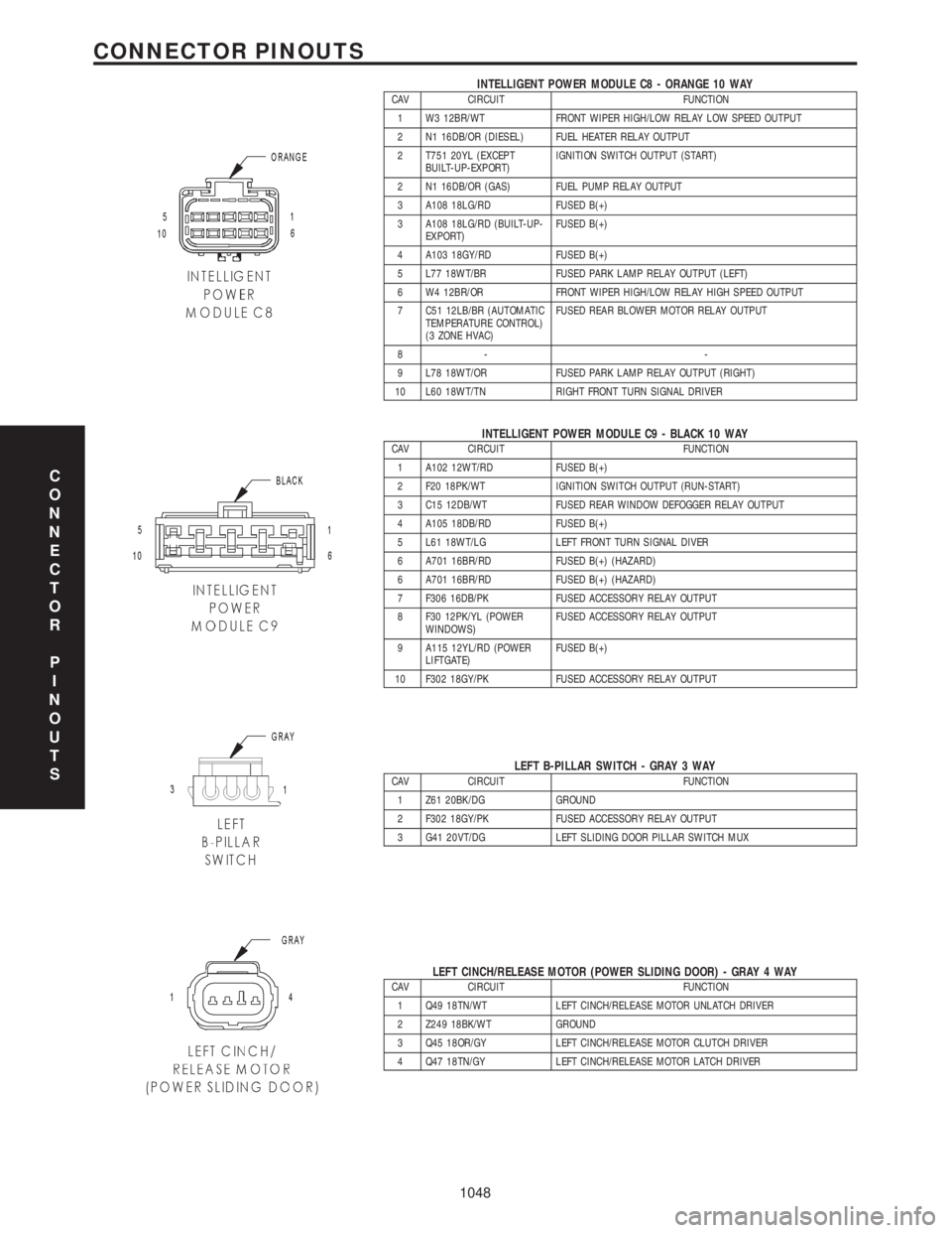
INTELLIGENT POWER MODULE C8 - ORANGE 10 WAYCAV CIRCUIT FUNCTION
1 W3 12BR/WT FRONT WIPER HIGH/LOW RELAY LOW SPEED OUTPUT
2 N1 16DB/OR (DIESEL) FUEL HEATER RELAY OUTPUT
2 T751 20YL (EXCEPT
BUILT-UP-EXPORT)IGNITION SWITCH OUTPUT (START)
2 N1 16DB/OR (GAS) FUEL PUMP RELAY OUTPUT
3 A108 18LG/RD FUSED B(+)
3 A108 18LG/RD (BUILT-UP-
EXPORT)FUSED B(+)
4 A103 18GY/RD FUSED B(+)
5 L77 18WT/BR FUSED PARK LAMP RELAY OUTPUT (LEFT)
6 W4 12BR/OR FRONT WIPER HIGH/LOW RELAY HIGH SPEED OUTPUT
7 C51 12LB/BR (AUTOMATIC
TEMPERATURE CONTROL)
(3 ZONE HVAC)FUSED REAR BLOWER MOTOR RELAY OUTPUT
8- -
9 L78 18WT/OR FUSED PARK LAMP RELAY OUTPUT (RIGHT)
10 L60 18WT/TN RIGHT FRONT TURN SIGNAL DRIVER
INTELLIGENT POWER MODULE C9 - BLACK 10 WAYCAV CIRCUIT FUNCTION
1 A102 12WT/RD FUSED B(+)
2 F20 18PK/WT IGNITION SWITCH OUTPUT (RUN-START)
3 C15 12DB/WT FUSED REAR WINDOW DEFOGGER RELAY OUTPUT
4 A105 18DB/RD FUSED B(+)
5 L61 18WT/LG LEFT FRONT TURN SIGNAL DIVER
6 A701 16BR/RD FUSED B(+) (HAZARD)
6 A701 16BR/RD FUSED B(+) (HAZARD)
7 F306 16DB/PK FUSED ACCESSORY RELAY OUTPUT
8 F30 12PK/YL (POWER
WINDOWS)FUSED ACCESSORY RELAY OUTPUT
9 A115 12YL/RD (POWER
LIFTGATE)FUSED B(+)
10 F302 18GY/PK FUSED ACCESSORY RELAY OUTPUT
LEFT B-PILLAR SWITCH - GRAY 3 WAYCAV CIRCUIT FUNCTION
1 Z61 20BK/DG GROUND
2 F302 18GY/PK FUSED ACCESSORY RELAY OUTPUT
3 G41 20VT/DG LEFT SLIDING DOOR PILLAR SWITCH MUX
LEFT CINCH/RELEASE MOTOR (POWER SLIDING DOOR) - GRAY 4 WAYCAV CIRCUIT FUNCTION
1 Q49 18TN/WT LEFT CINCH/RELEASE MOTOR UNLATCH DRIVER
2 Z249 18BK/WT GROUND
3 Q45 18OR/GY LEFT CINCH/RELEASE MOTOR CLUTCH DRIVER
4 Q47 18TN/GY LEFT CINCH/RELEASE MOTOR LATCH DRIVER
C
O
N
N
E
C
T
O
R
P
I
N
O
U
T
S
1048
CONNECTOR PINOUTS
Page 1081 of 4284
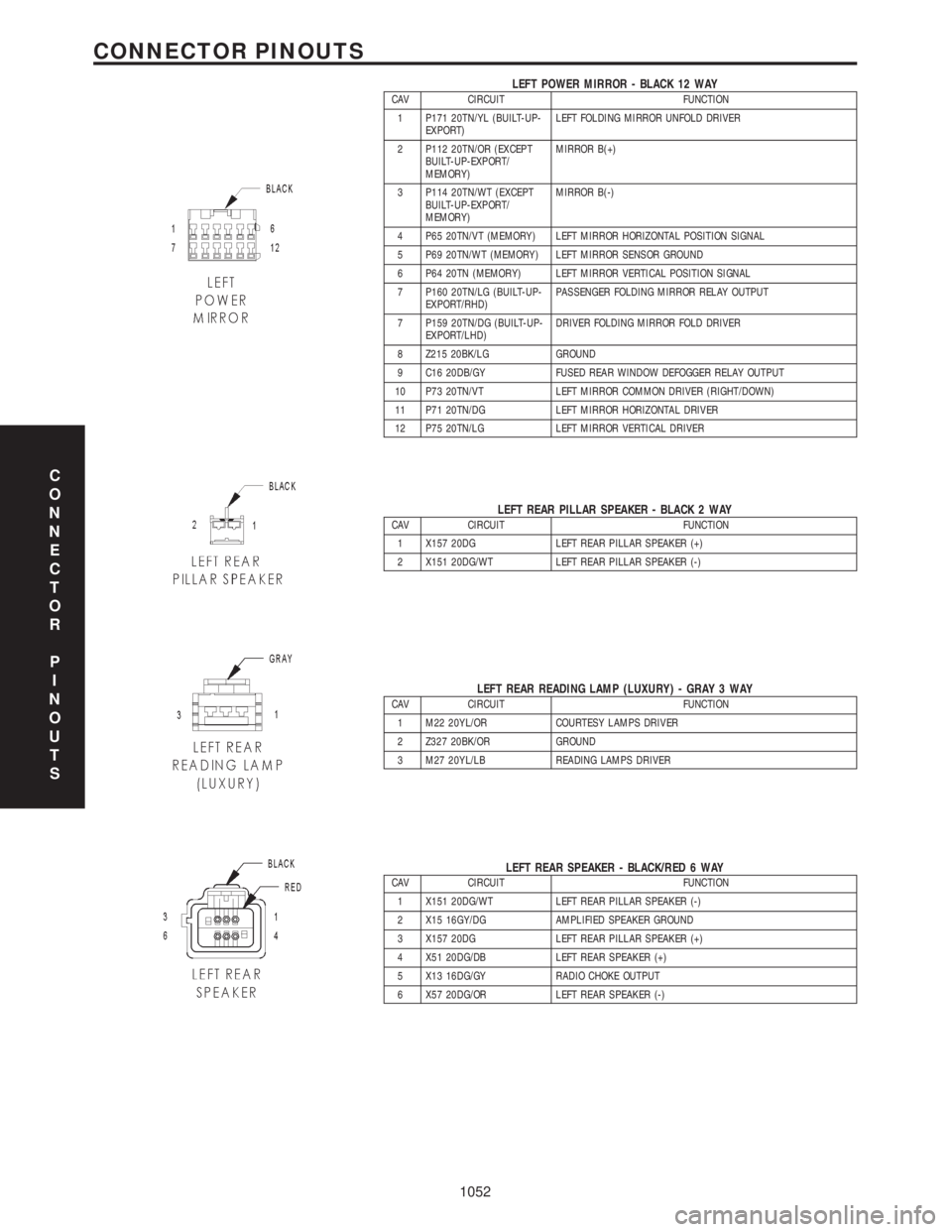
LEFT POWER MIRROR - BLACK 12 WAYCAV CIRCUIT FUNCTION
1 P171 20TN/YL (BUILT-UP-
EXPORT)LEFT FOLDING MIRROR UNFOLD DRIVER
2 P112 20TN/OR (EXCEPT
BUILT-UP-EXPORT/
MEMORY)MIRROR B(+)
3 P114 20TN/WT (EXCEPT
BUILT-UP-EXPORT/
MEMORY)MIRROR B(-)
4 P65 20TN/VT (MEMORY) LEFT MIRROR HORIZONTAL POSITION SIGNAL
5 P69 20TN/WT (MEMORY) LEFT MIRROR SENSOR GROUND
6 P64 20TN (MEMORY) LEFT MIRROR VERTICAL POSITION SIGNAL
7 P160 20TN/LG (BUILT-UP-
EXPORT/RHD)PASSENGER FOLDING MIRROR RELAY OUTPUT
7 P159 20TN/DG (BUILT-UP-
EXPORT/LHD)DRIVER FOLDING MIRROR FOLD DRIVER
8 Z215 20BK/LG GROUND
9 C16 20DB/GY FUSED REAR WINDOW DEFOGGER RELAY OUTPUT
10 P73 20TN/VT LEFT MIRROR COMMON DRIVER (RIGHT/DOWN)
11 P71 20TN/DG LEFT MIRROR HORIZONTAL DRIVER
12 P75 20TN/LG LEFT MIRROR VERTICAL DRIVER
LEFT REAR PILLAR SPEAKER - BLACK 2 WAYCAV CIRCUIT FUNCTION
1 X157 20DG LEFT REAR PILLAR SPEAKER (+)
2 X151 20DG/WT LEFT REAR PILLAR SPEAKER (-)
LEFT REAR READING LAMP (LUXURY) - GRAY 3 WAYCAV CIRCUIT FUNCTION
1 M22 20YL/OR COURTESY LAMPS DRIVER
2 Z327 20BK/OR GROUND
3 M27 20YL/LB READING LAMPS DRIVER
LEFT REAR SPEAKER - BLACK/RED 6 WAYCAV CIRCUIT FUNCTION
1 X151 20DG/WT LEFT REAR PILLAR SPEAKER (-)
2 X15 16GY/DG AMPLIFIED SPEAKER GROUND
3 X157 20DG LEFT REAR PILLAR SPEAKER (+)
4 X51 20DG/DB LEFT REAR SPEAKER (+)
5 X13 16DG/GY RADIO CHOKE OUTPUT
6 X57 20DG/OR LEFT REAR SPEAKER (-)
C
O
N
N
E
C
T
O
R
P
I
N
O
U
T
S
1052
CONNECTOR PINOUTS
Page 1092 of 4284
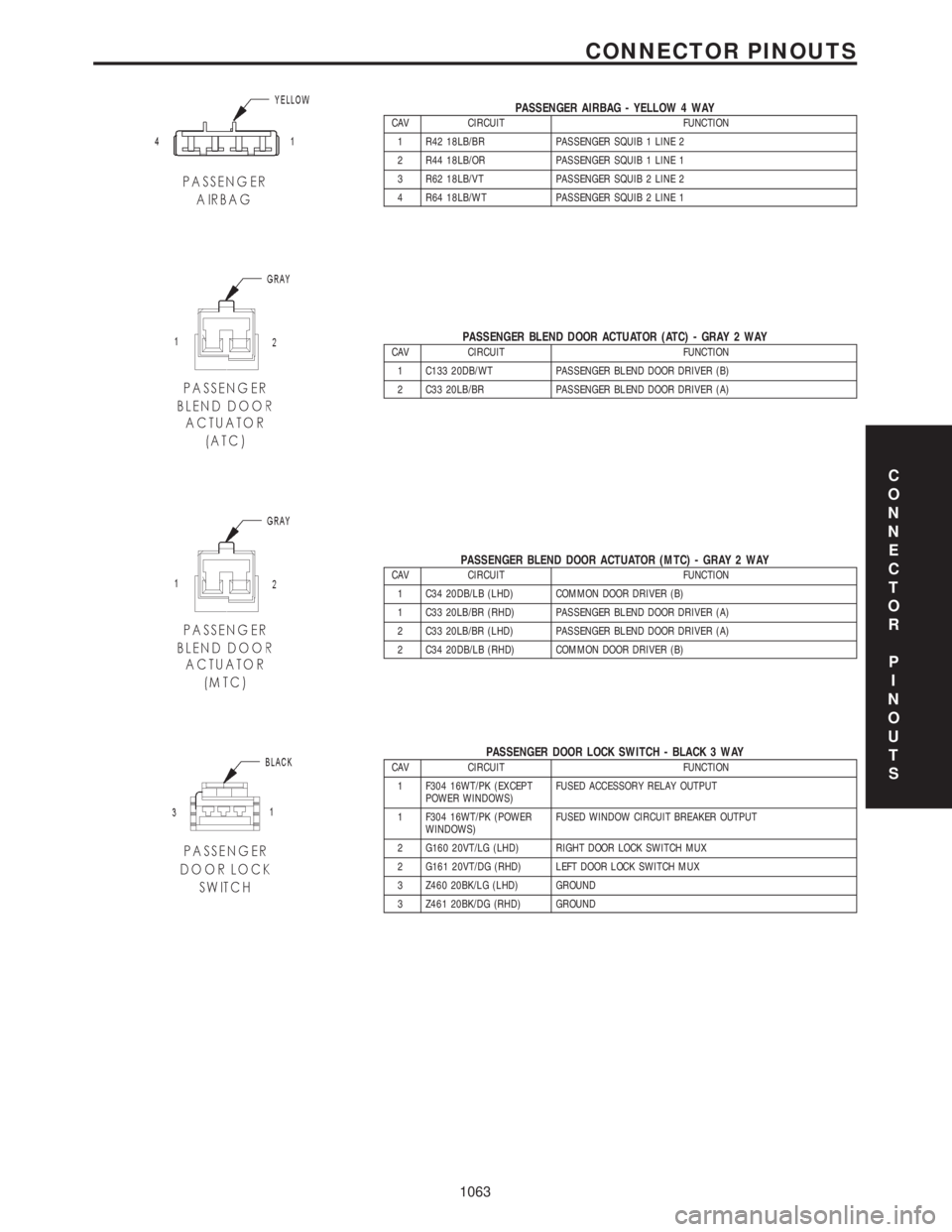
PASSENGER AIRBAG - YELLOW 4 WAYCAV CIRCUIT FUNCTION
1 R42 18LB/BR PASSENGER SQUIB 1 LINE 2
2 R44 18LB/OR PASSENGER SQUIB 1 LINE 1
3 R62 18LB/VT PASSENGER SQUIB 2 LINE 2
4 R64 18LB/WT PASSENGER SQUIB 2 LINE 1
PASSENGER BLEND DOOR ACTUATOR (ATC) - GRAY 2 WAYCAV CIRCUIT FUNCTION
1 C133 20DB/WT PASSENGER BLEND DOOR DRIVER (B)
2 C33 20LB/BR PASSENGER BLEND DOOR DRIVER (A)
PASSENGER BLEND DOOR ACTUATOR (MTC) - GRAY 2 WAYCAV CIRCUIT FUNCTION
1 C34 20DB/LB (LHD) COMMON DOOR DRIVER (B)
1 C33 20LB/BR (RHD) PASSENGER BLEND DOOR DRIVER (A)
2 C33 20LB/BR (LHD) PASSENGER BLEND DOOR DRIVER (A)
2 C34 20DB/LB (RHD) COMMON DOOR DRIVER (B)
PASSENGER DOOR LOCK SWITCH - BLACK 3 WAYCAV CIRCUIT FUNCTION
1 F304 16WT/PK (EXCEPT
POWER WINDOWS)FUSED ACCESSORY RELAY OUTPUT
1 F304 16WT/PK (POWER
WINDOWS)FUSED WINDOW CIRCUIT BREAKER OUTPUT
2 G160 20VT/LG (LHD) RIGHT DOOR LOCK SWITCH MUX
2 G161 20VT/DG (RHD) LEFT DOOR LOCK SWITCH MUX
3 Z460 20BK/LG (LHD) GROUND
3 Z461 20BK/DG (RHD) GROUND
C
O
N
N
E
C
T
O
R
P
I
N
O
U
T
S
1063
CONNECTOR PINOUTS