window CHRYSLER VOYAGER 2001 Owner's Manual
[x] Cancel search | Manufacturer: CHRYSLER, Model Year: 2001, Model line: VOYAGER, Model: CHRYSLER VOYAGER 2001Pages: 4284, PDF Size: 83.53 MB
Page 1095 of 4284
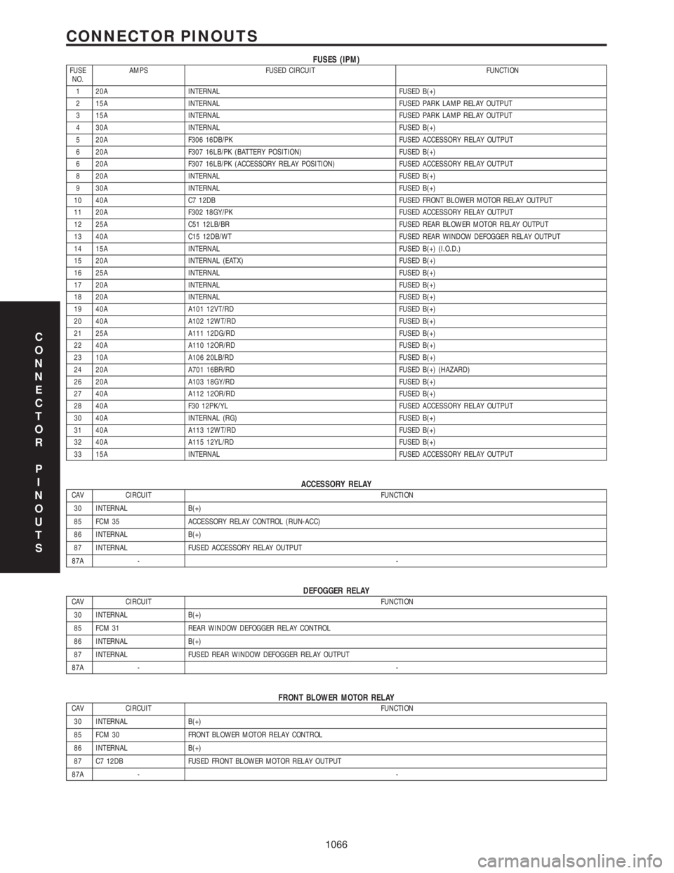
FUSES (IPM)FUSE
NO.AMPS FUSED CIRCUIT FUNCTION
1 20A INTERNAL FUSED B(+)
2 15A INTERNAL FUSED PARK LAMP RELAY OUTPUT
3 15A INTERNAL FUSED PARK LAMP RELAY OUTPUT
4 30A INTERNAL FUSED B(+)
5 20A F306 16DB/PK FUSED ACCESSORY RELAY OUTPUT
6 20A F307 16LB/PK (BATTERY POSITION) FUSED B(+)
6 20A F307 16LB/PK (ACCESSORY RELAY POSITION) FUSED ACCESSORY RELAY OUTPUT
8 20A INTERNAL FUSED B(+)
9 30A INTERNAL FUSED B(+)
10 40A C7 12DB FUSED FRONT BLOWER MOTOR RELAY OUTPUT
11 20A F302 18GY/PK FUSED ACCESSORY RELAY OUTPUT
12 25A C51 12LB/BR FUSED REAR BLOWER MOTOR RELAY OUTPUT
13 40A C15 12DB/WT FUSED REAR WINDOW DEFOGGER RELAY OUTPUT
14 15A INTERNAL FUSED B(+) (I.O.D.)
15 20A INTERNAL (EATX) FUSED B(+)
16 25A INTERNAL FUSED B(+)
17 20A INTERNAL FUSED B(+)
18 20A INTERNAL FUSED B(+)
19 40A A101 12VT/RD FUSED B(+)
20 40A A102 12WT/RD FUSED B(+)
21 25A A111 12DG/RD FUSED B(+)
22 40A A110 12OR/RD FUSED B(+)
23 10A A106 20LB/RD FUSED B(+)
24 20A A701 16BR/RD FUSED B(+) (HAZARD)
26 20A A103 18GY/RD FUSED B(+)
27 40A A112 12OR/RD FUSED B(+)
28 40A F30 12PK/YL FUSED ACCESSORY RELAY OUTPUT
30 40A INTERNAL (RG) FUSED B(+)
31 40A A113 12WT/RD FUSED B(+)
32 40A A115 12YL/RD FUSED B(+)
33 15A INTERNAL FUSED ACCESSORY RELAY OUTPUT
ACCESSORY RELAYCAV CIRCUIT FUNCTION
30 INTERNAL B(+)
85 FCM 35 ACCESSORY RELAY CONTROL (RUN-ACC)
86 INTERNAL B(+)
87 INTERNAL FUSED ACCESSORY RELAY OUTPUT
87A --
DEFOGGER RELAYCAV CIRCUIT FUNCTION
30 INTERNAL B(+)
85 FCM 31 REAR WINDOW DEFOGGER RELAY CONTROL
86 INTERNAL B(+)
87 INTERNAL FUSED REAR WINDOW DEFOGGER RELAY OUTPUT
87A --
FRONT BLOWER MOTOR RELAYCAV CIRCUIT FUNCTION
30 INTERNAL B(+)
85 FCM 30 FRONT BLOWER MOTOR RELAY CONTROL
86 INTERNAL B(+)
87 C7 12DB FUSED FRONT BLOWER MOTOR RELAY OUTPUT
87A --
C
O
N
N
E
C
T
O
R
P
I
N
O
U
T
S
1066
CONNECTOR PINOUTS
Page 1096 of 4284
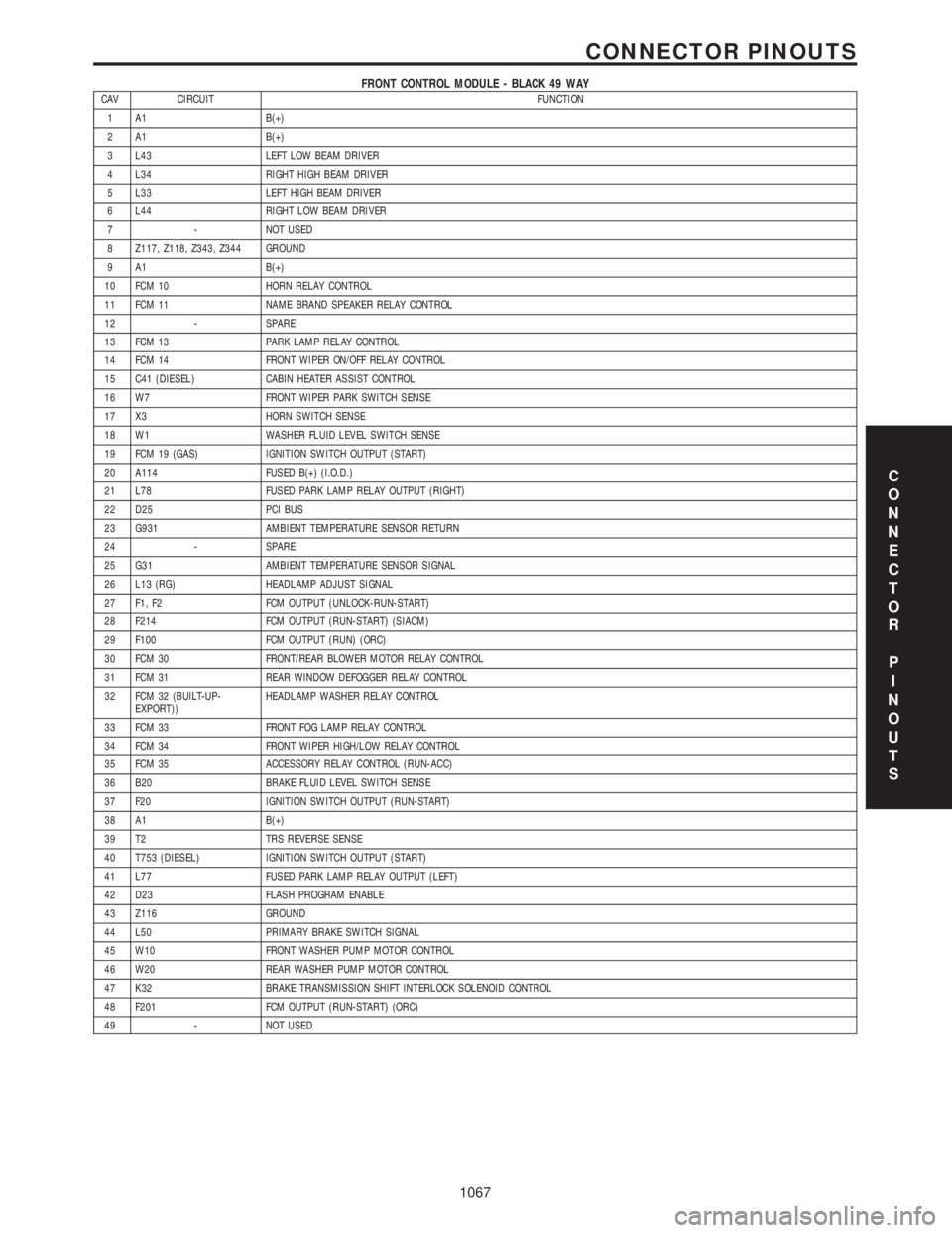
FRONT CONTROL MODULE - BLACK 49 WAYCAV CIRCUIT FUNCTION
1 A1 B(+)
2 A1 B(+)
3 L43 LEFT LOW BEAM DRIVER
4 L34 RIGHT HIGH BEAM DRIVER
5 L33 LEFT HIGH BEAM DRIVER
6 L44 RIGHT LOW BEAM DRIVER
7 - NOT USED
8 Z117, Z118, Z343, Z344 GROUND
9 A1 B(+)
10 FCM 10 HORN RELAY CONTROL
11 FCM 11 NAME BRAND SPEAKER RELAY CONTROL
12 - SPARE
13 FCM 13 PARK LAMP RELAY CONTROL
14 FCM 14 FRONT WIPER ON/OFF RELAY CONTROL
15 C41 (DIESEL) CABIN HEATER ASSIST CONTROL
16 W7 FRONT WIPER PARK SWITCH SENSE
17 X3 HORN SWITCH SENSE
18 W1 WASHER FLUID LEVEL SWITCH SENSE
19 FCM 19 (GAS) IGNITION SWITCH OUTPUT (START)
20 A114 FUSED B(+) (I.O.D.)
21 L78 FUSED PARK LAMP RELAY OUTPUT (RIGHT)
22 D25 PCI BUS
23 G931 AMBIENT TEMPERATURE SENSOR RETURN
24 - SPARE
25 G31 AMBIENT TEMPERATURE SENSOR SIGNAL
26 L13 (RG) HEADLAMP ADJUST SIGNAL
27 F1, F2 FCM OUTPUT (UNLOCK-RUN-START)
28 F214 FCM OUTPUT (RUN-START) (SIACM)
29 F100 FCM OUTPUT (RUN) (ORC)
30 FCM 30 FRONT/REAR BLOWER MOTOR RELAY CONTROL
31 FCM 31 REAR WINDOW DEFOGGER RELAY CONTROL
32 FCM 32 (BUILT-UP-
EXPORT))HEADLAMP WASHER RELAY CONTROL
33 FCM 33 FRONT FOG LAMP RELAY CONTROL
34 FCM 34 FRONT WIPER HIGH/LOW RELAY CONTROL
35 FCM 35 ACCESSORY RELAY CONTROL (RUN-ACC)
36 B20 BRAKE FLUID LEVEL SWITCH SENSE
37 F20 IGNITION SWITCH OUTPUT (RUN-START)
38 A1 B(+)
39 T2 TRS REVERSE SENSE
40 T753 (DIESEL) IGNITION SWITCH OUTPUT (START)
41 L77 FUSED PARK LAMP RELAY OUTPUT (LEFT)
42 D23 FLASH PROGRAM ENABLE
43 Z116 GROUND
44 L50 PRIMARY BRAKE SWITCH SIGNAL
45 W10 FRONT WASHER PUMP MOTOR CONTROL
46 W20 REAR WASHER PUMP MOTOR CONTROL
47 K32 BRAKE TRANSMISSION SHIFT INTERLOCK SOLENOID CONTROL
48 F201 FCM OUTPUT (RUN-START) (ORC)
49 - NOT USED
C
O
N
N
E
C
T
O
R
P
I
N
O
U
T
S
1067
CONNECTOR PINOUTS
Page 1097 of 4284

FRONT FOG LAMP RELAYCAV CIRCUIT FUNCTION
30 INTERNAL FUSED B(+)
85 FCM 33 FRONT FOG LAMP RELAY CONTROL
86 INTERNAL FUSED B(+)
87 INTERNAL FRONT FOG LAMP RELAY OUTPUT
87A --
HEADLAMP WASHER RELAY (BUILT-UP-EXPORT)CAV CIRCUIT FUNCTION
30 INTERNAL FUSED B(+)
57 T55 20YL/VT (AUTOSTICK)
85 FCM 32 HEADLAMP WASHER RELAY CONTROL
86 INTERNAL FUSED B(+)
87 V53 12BR/OR HEADLAMP WASHER RELAY OUTPUT
87A - No Function Defined
NAME BRAND SPEAKER RELAYCAV CIRCUIT FUNCTION
30 INTERNAL FUSED B(+) (I.O.D.)
85 FCM 11 NAME BRAND SPEAKER (NBS) RELAY CONTROL
86 INTERNAL FUSED B(+) (I.O.D.)
87 X1 16DG/BR NAME BRAND SPEAKER (NBS) RELAY OUTPUT
87A --
PARK LAMP RELAYCAV CIRCUIT FUNCTION
30 INTERNAL B(+)
85 FCM 13 PARK LAMP RELAY CONTROL
86 INTERNAL B(+)
87 INTERNAL PARK LAMP RELAY OUTPUT
87A --
POSITIVE TEMPERATURE COEFFICIENTSFUSE
NO.AMPS FUSED CIRCUIT FUNCTION
4 8A C16 18DB/GY FUSED REAR WINDOW DEFOGGER RELAY OUTPUT
7 13A A105 18DB/RD FUSED B(+)
REAR BLOWER MOTOR RELAYCAV CIRCUIT FUNCTION
30 INTERNAL B(+)
85 FCM 30 REAR BLOWER MOTOR RELAY CONTROL
86 INTERNAL B(+)
87 C51 12LB/BR FUSED REAR BLOWER MOTOR RELAY OUTPUT
87A --
C
O
N
N
E
C
T
O
R
P
I
N
O
U
T
S
1068
CONNECTOR PINOUTS
Page 1109 of 4284
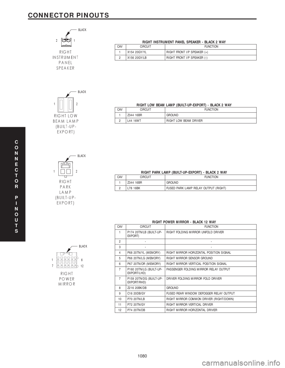
RIGHT INSTRUMENT PANEL SPEAKER - BLACK 2 WAYCAV CIRCUIT FUNCTION
1 X154 20GY/YL RIGHT FRONT I/P SPEAKER (+)
2 X156 20GY/LB RIGHT FRONT I/P SPEAKER (-)
RIGHT LOW BEAM LAMP (BUILT-UP-EXPORT) - BLACK 2 WAYCAV CIRCUIT FUNCTION
1 Z344 16BR GROUND
2 L44 16WT RIGHT LOW BEAM DRIVER
RIGHT PARK LAMP (BUILT-UP-EXPORT) - BLACK 2 WAYCAV CIRCUIT FUNCTION
1 Z344 16BR GROUND
2 L78 16BK FUSED PARK LAMP RELAY OUTPUT (RIGHT)
RIGHT POWER MIRROR - BLACK 12 WAYCAV CIRCUIT FUNCTION
1 P174 20TN/LB (BUILT-UP-
EXPORT)RIGHT FOLDING MIRROR UNFOLD DRIVER
2- -
3- -
4 P68 20TN/YL (MEMORY) RIGHT MIRROR HORIZONTAL POSITION SIGNAL
5 P66 20TN/LG (MEMORY) RIGHT MIRROR SENSOR GROUND
6 P67 20TN/OR (MEMORY) RIGHT MIRROR VERTICAL POSITION SIGNAL
7 P160 20TN/LG (BUILT-UP-
EXPORT/LHD)PASSENGER FOLDING MIRROR RELAY OUTPUT
7 P159 20TN/DG (BUILT-UP-
EXPORT/RHD)DRIVER FOLDING MIRROR FOLD DRIVER
8 Z216 20BK/DB GROUND
9 C16 20DB/GY FUSED REAR WINDOW DEFOGGER RELAY OUTPUT
10 P70 20TN/LB RIGHT MIRROR COMMON DRIVER (RIGHT/DOWN)
11 P72 20TN/GY RIGHT MIRROR VERTICAL DRIVER
12 P74 20TN/DB RIGHT MIRROR HORIZONTAL DRIVER
C
O
N
N
E
C
T
O
R
P
I
N
O
U
T
S
1080
CONNECTOR PINOUTS
Page 1208 of 4284
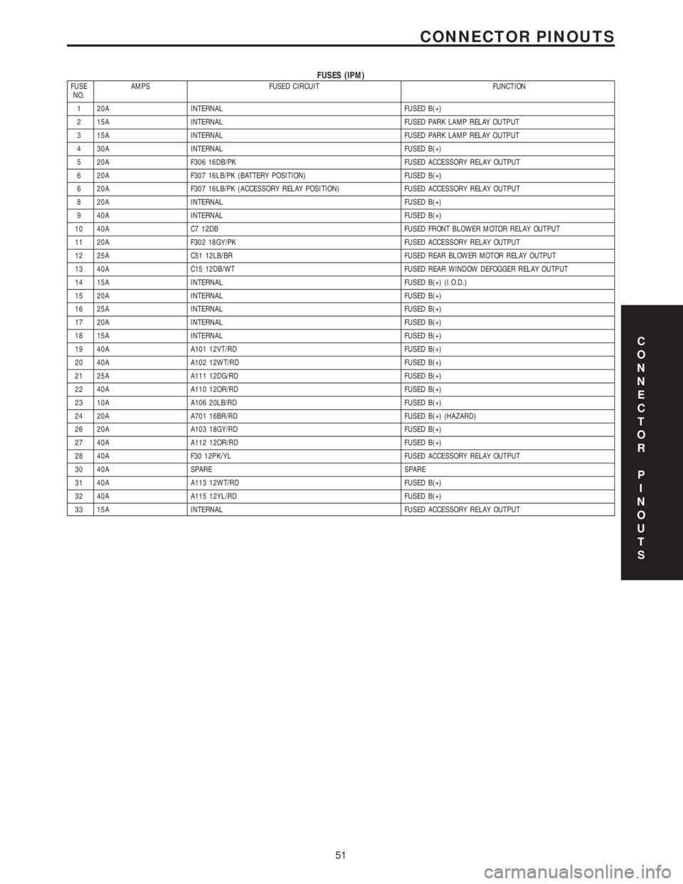
FUSES (IPM)FUSE
NO.AMPS FUSED CIRCUIT FUNCTION
1 20A INTERNAL FUSED B(+)
2 15A INTERNAL FUSED PARK LAMP RELAY OUTPUT
3 15A INTERNAL FUSED PARK LAMP RELAY OUTPUT
4 30A INTERNAL FUSED B(+)
5 20A F306 16DB/PK FUSED ACCESSORY RELAY OUTPUT
6 20A F307 16LB/PK (BATTERY POSITION) FUSED B(+)
6 20A F307 16LB/PK (ACCESSORY RELAY POSITION) FUSED ACCESSORY RELAY OUTPUT
8 20A INTERNAL FUSED B(+)
9 40A INTERNAL FUSED B(+)
10 40A C7 12DB FUSED FRONT BLOWER MOTOR RELAY OUTPUT
11 20A F302 18GY/PK FUSED ACCESSORY RELAY OUTPUT
12 25A C51 12LB/BR FUSED REAR BLOWER MOTOR RELAY OUTPUT
13 40A C15 12DB/WT FUSED REAR WINDOW DEFOGGER RELAY OUTPUT
14 15A INTERNAL FUSED B(+) (I.O.D.)
15 20A INTERNAL FUSED B(+)
16 25A INTERNAL FUSED B(+)
17 20A INTERNAL FUSED B(+)
18 15A INTERNAL FUSED B(+)
19 40A A101 12VT/RD FUSED B(+)
20 40A A102 12WT/RD FUSED B(+)
21 25A A111 12DG/RD FUSED B(+)
22 40A A110 12OR/RD FUSED B(+)
23 10A A106 20LB/RD FUSED B(+)
24 20A A701 16BR/RD FUSED B(+) (HAZARD)
26 20A A103 18GY/RD FUSED B(+)
27 40A A112 12OR/RD FUSED B(+)
28 40A F30 12PK/YL FUSED ACCESSORY RELAY OUTPUT
30 40A SPARE SPARE
31 40A A113 12WT/RD FUSED B(+)
32 40A A115 12YL/RD FUSED B(+)
33 15A INTERNAL FUSED ACCESSORY RELAY OUTPUT
C
O
N
N
E
C
T
O
R
P
I
N
O
U
T
S
51
CONNECTOR PINOUTS
Page 1473 of 4284

FASTENER IDENTIFICATION
DESCRIPTION
The SAE bolt strength grades range from grade 2
to grade 8. The higher the grade number, the greater
the bolt strength. Identification is determined by the
line marks on the top of each bolt head. The actual
bolt strength grade corresponds to the number of line
marks plus 2. The most commonly used metric bolt
strength classes are 9.8 and 10.9. The metric
strength class identification number is imprinted on
the head of the bolt. The higher the class number,
the greater the bolt strength. Some metric nuts are
imprinted with a single-digit strength class on the
nut face. Refer to the Fastener Identification and
Fastener Strength Charts.
FASTENER USAGE
DESCRIPTION - FASTENER USAGE
WARNING: USE OF AN INCORRECT FASTENER
MAY RESULT IN COMPONENT DAMAGE OR PER-
SONAL INJURY.
Figure art, specifications and torque references in
this Service Manual are identified in metric and SAE
format.
During any maintenance or repair procedures, it is
important to salvage all fasteners (nuts, bolts, etc.)
for reassembly. If the fastener is not salvageable, a
fastener of equivalent specification must be used.
International Symbols
1 High Beam 13 Rear Window Washer
2 Fog Lamps 14 Fuel
3 Headlamp, Parking Lamps, Panel Lamps 15 Engine Coolant Temperature
4 Turn Warning 16 Battery Charging Condition
5 Hazard Warning 17 Engine Oil
6 Windshield Washer 18 Seat Belt
7 Windshield Wiper 19 Brake Failure
8 Windshield Wiper and Washer 20 Parking Brake
9 Windscreen Demisting and Defrosting 21 Front Hood
10 Ventilating Fan 22 Rear hood (Decklid)
11 Rear Window Defogger 23 Horn
12 Rear Window Wiper 24 Lighter
RSINTRODUCTION5
INTERNATIONAL SYMBOLS (Continued)
Page 1483 of 4284

FASTENER USAGE
DESCRIPTION
WARNING: USE OF AN INCORRECT FASTENER
MAY RESULT IN COMPONENT DAMAGE OR PER-
SONAL INJURY.
Figure art, specifications and torque references in
this Service Manual are identified in metric and SAE
format.
During any maintenance or repair procedures, it is
important to salvage all fasteners (nuts, bolts, etc.)
for reassembly. If the fastener is not salvageable, a
fastener of equivalent specification must be used.
THREADED HOLE REPAIR
DESCRIPTION
Most stripped threaded holes can be repaired using
a Helicoilt. Follow the vehicle or Helicoiltrecommen-
dations for application and repair procedures.
INTERNATIONAL VEHICLE
CONTROL & DISPLAY
SYMBOLS
DESCRIPTION
The graphic symbols illustrated in the following
International Control and Display Symbols Chart
(Fig. 4) are used to identify various instrument con-
trols. The symbols correspond to the controls and dis-
plays that are located on the instrument panel.
Fig. 4 INTERNATIONAL CONTROL AND DISPLAY SYMBOLS
1 High Beam 13 Rear Window Washer
2 Fog Lamps 14 Fuel
3 Headlamp, Parking Lamps, Panel Lamps 15 Engine Coolant Temperature
4 Turn Warning 16 Battery Charging Condition
5 Hazard Warning 17 Engine Oil
6 Windshield Washer 18 Seat Belt
7 Windshield Wiper 19 Brake Failure
8 Windshield Wiper and Washer 20 Parking Brake
9 Windscreen Demisting and Defrosting 21 Front Hood
10 Ventilating Fan 22 Rear hood (Decklid)
11 Rear Window Defogger 23 Horn
12 Rear Window Wiper 24 Lighter
RGINTRODUCTION5a
Page 1817 of 4284
AUDIO
TABLE OF CONTENTS
page page
QUARTER GLASS INTEGRAL ANTENNA
DESCRIPTION............................1
OPERATION.............................1
DIAGNOSIS AND TESTING..................1
QUARTER GLASS INTEGRAL ANTENNA......1
ANTENNA MODULE
DESCRIPTION............................2OPERATION.............................2
DIAGNOSIS AND TESTING..................2
ANTENNA MODULE......................2
REMOVAL...............................2
INSTALLATION............................2
QUARTER GLASS INTEGRAL
ANTENNA
DESCRIPTION
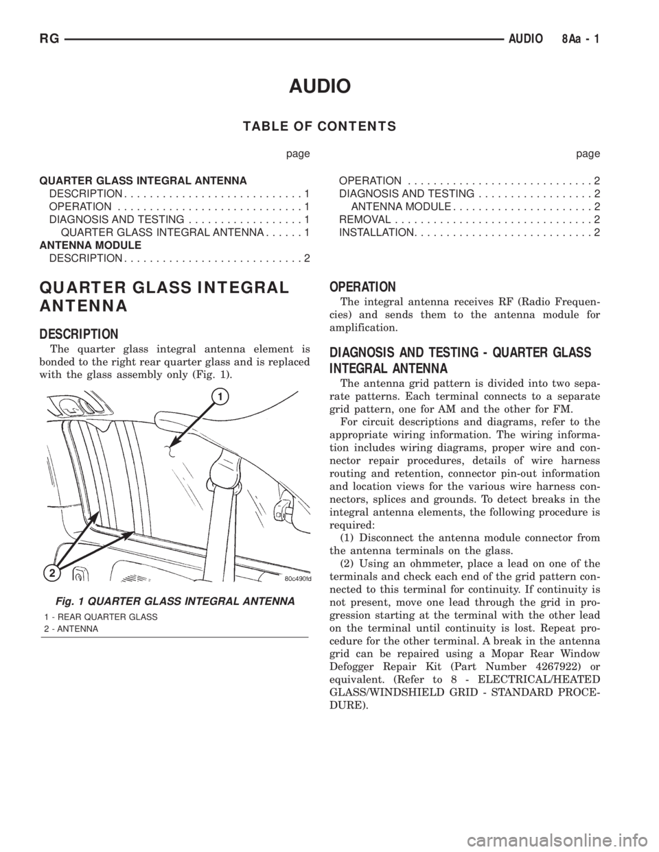
The quarter glass integral antenna element is
bonded to the right rear quarter glass and is replaced
with the glass assembly only (Fig. 1).
OPERATION
The integral antenna receives RF (Radio Frequen-
cies) and sends them to the antenna module for
amplification.
DIAGNOSIS AND TESTING - QUARTER GLASS
INTEGRAL ANTENNA
The antenna grid pattern is divided into two sepa-
rate patterns. Each terminal connects to a separate
grid pattern, one for AM and the other for FM.
For circuit descriptions and diagrams, refer to the
appropriate wiring information. The wiring informa-
tion includes wiring diagrams, proper wire and con-
nector repair procedures, details of wire harness
routing and retention, connector pin-out information
and location views for the various wire harness con-
nectors, splices and grounds. To detect breaks in the
integral antenna elements, the following procedure is
required:
(1) Disconnect the antenna module connector from
the antenna terminals on the glass.
(2) Using an ohmmeter, place a lead on one of the
terminals and check each end of the grid pattern con-
nected to this terminal for continuity. If continuity is
not present, move one lead through the grid in pro-
gression starting at the terminal with the other lead
on the terminal until continuity is lost. Repeat pro-
cedure for the other terminal. A break in the antenna
grid can be repaired using a Mopar Rear Window
Defogger Repair Kit (Part Number 4267922) or
equivalent. (Refer to 8 - ELECTRICAL/HEATED
GLASS/WINDSHIELD GRID - STANDARD PROCE-
DURE).
Fig. 1 QUARTER GLASS INTEGRAL ANTENNA
1 - REAR QUARTER GLASS
2 - ANTENNA
RGAUDIO8Aa-1
Page 1818 of 4284
ANTENNA MODULE
DESCRIPTION
The antenna module is an electromagnetic circuit
component designed to capture and enhance RF
(Radio Frequency) signals in both the AM and FM
broadcast bands. The antenna module is mounted to
the right rear roof rail under the headliner. The mod-
ule is grounded through the mounting bracket and
fastener. The module has a two wire electrical con-
nector that connects to the integral radio antenna,located on the right rear quarter glass. There is also
an electrical connector for battery voltage and a coax
cable connector.OPERATION
The antenna module receives both AM and FM
radio signals supplied by the side window integral
radio antenna system and selectively amplifies them.
The amplified signal is then sent through the body
length coax cable to the radio input.
DIAGNOSIS AND TESTING - ANTENNA MODULE
CONDITION POSSIBLE CAUSES CORRECTION
NO AM RECEPTION,
WEAK FM RECEPTION1. Antenna module to antenna
connector open or disconnected.1. Repair open, reconnect
antenna module connector to
glass mounted antenna.
2. Coax open or disconnected. 2. Repair open, reconnect coax.
3. No battery power at antenna
module.3. Check fuse. if okay, repair
open in battery voltage circuit.
NO AM OR FM
RECEPTION1. Coax disconnected at radio. 1. Reconnect coax.
2. Coax shorted to ground. 2. Repair or Replace coax
WEAK OR NO AM/FM
RECEPTION1. Antenna Module faulty. 1. Substitute known good
module. If reception improves,
Antenna Module was faulty.
REMOVAL
(1) Disconnect and isolate the battery negative
cable.
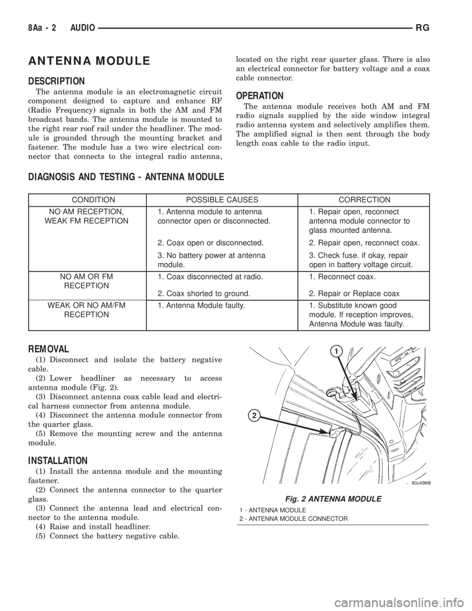
(2) Lower headliner as necessary to access
antenna module (Fig. 2).
(3) Disconnect antenna coax cable lead and electri-
cal harness connector from antenna module.
(4) Disconnect the antenna module connector from
the quarter glass.
(5) Remove the mounting screw and the antenna
module.
INSTALLATION
(1) Install the antenna module and the mounting
fastener.
(2) Connect the antenna connector to the quarter
glass.
(3) Connect the antenna lead and electrical con-
nector to the antenna module.
(4) Raise and install headliner.
(5) Connect the battery negative cable.
Fig. 2 ANTENNA MODULE
1 - ANTENNA MODULE
2 - ANTENNA MODULE CONNECTOR
8Aa - 2 AUDIORG
Page 1897 of 4284
HEATED SYSTEMS
TABLE OF CONTENTS
page page
HEATED GLASS........................... 1
HEATED MIRRORS......................... 5HEATED SEAT SYSTEM..................... 7
HEATED GLASS
TABLE OF CONTENTS
page page
HEATED GLASS
DESCRIPTION............................1
OPERATION.............................2
DEFOGGER RELAY
DESCRIPTION............................2
REAR WINDOW DEFOGGER GRID
STANDARD PROCEDURE...................2
GRID LINE REPAIR-REAR.................2REAR WINDOW DEFOGGER SWITCH
DESCRIPTION............................2
OPERATION.............................2
WINDSHIELD GRID
DIAGNOSIS AND TESTING..................3
SYSTEM TEST..........................3
STANDARD PROCEDURE...................3
GRID LINE AND TERMINAL REPAIR.........3
HEATED GLASS
DESCRIPTION
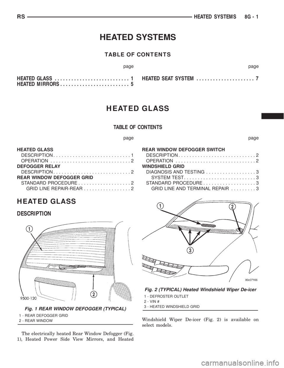
The electrically heated Rear Window Defogger (Fig.
1), Heated Power Side View Mirrors, and HeatedWindshield Wiper De-icer (Fig. 2) is available on
select models.
Fig. 1 REAR WINDOW DEFOGGER (TYPICAL)
1 - REAR DEFOGGER GRID
2 - REAR WINDOW
Fig. 2 (TYPICAL) Heated Windshield Wiper De-icer
1 - DEFROSTER OUTLET
2 - VIN #
3 - HEATED WINDSHIELD GRID
RSHEATED SYSTEMS8G-1