window CHRYSLER VOYAGER 2001 Manual Online
[x] Cancel search | Manufacturer: CHRYSLER, Model Year: 2001, Model line: VOYAGER, Model: CHRYSLER VOYAGER 2001Pages: 4284, PDF Size: 83.53 MB
Page 3532 of 4284
DOOR - FRONT
TABLE OF CONTENTS
page page
APPLIQUE
REMOVAL.............................152
INSTALLATION..........................152
CHECK STRAP
REMOVAL.............................152
INSTALLATION..........................153
DOOR
REMOVAL.............................153
INSTALLATION..........................154
DOOR GLASS
REMOVAL.............................155
INSTALLATION..........................155
FRAME CLOSEOUT MOLDING
REMOVAL.............................155
INSTALLATION..........................156
HINGE
REMOVAL.............................156
INSTALLATION..........................156
LATCH
REMOVAL.............................156
INSTALLATION..........................157
LATCH STRIKER
REMOVAL.............................157INSTALLATION..........................157
LOCK CYLINDER
REMOVAL.............................157
INSTALLATION..........................157
TRIM PANEL
REMOVAL.............................158
INSTALLATION..........................158
TRIM PANEL REFLECTOR
REMOVAL.............................159
INSTALLATION..........................159
WATERSHIELD
REMOVAL.............................159
INSTALLATION..........................159
WINDOW CRANK
REMOVAL.............................159
INSTALLATION..........................159
WINDOW REGULATOR
REMOVAL.............................160
INSTALLATION..........................160
EXTERIOR HANDLE
REMOVAL.............................161
INSTALLATION..........................161
APPLIQUE
REMOVAL
(1) Roll door glass down.
(2) Remove outer door belt molding.
(3) Disengage clips holding front edge of applique
to door frame.
(4) Remove applique from vehicle (Fig. 1) .
INSTALLATION
(1) Position applique on vehicle.
(2)
Hook rear edge of applique over rear edge of door
frame and seat applique bottom edge on sheet metal.
(3) Engage clips to hold front edge of applique to
door frame.
(4) Install outer door belt molding.
CHECK STRAP
REMOVAL
(1) Remove front door watershield. (Refer to 23 -
BODY/DOOR - FRONT/WATERSHIELD -
REMOVAL)
(2) Remove bolts attaching door check strap to
A-pillar (Fig. 4).
(3) Remove nuts attaching check strap to door end
frame (Fig. 2).
(4) Remove check strap from door through speaker
hole.
23 - 152 DOOR - FRONTRS
Page 3535 of 4284
DOOR GLASS
REMOVAL
(1) Remove watershield. (Refer to 23 - BODY/
DOOR - FRONT/WATERSHIELD - REMOVAL)
(2) Remove inner belt molding.(Refer to 23 -
BODY/WEATHERSTRIP/SEALS/FDR INNER BELT
WEATHERSTRIP - REMOVAL)
(3) Remove outer belt molding.(Refer to 23 -
BODY/WEATHERSTRIP/SEALS/FDR OUTER BELT
MOLDING - REMOVAL)
(4) Position glass to gain access to front and rear
regulator lift plates through front and rear access
holes in door panel.
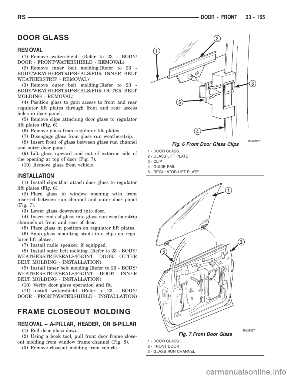
(5) Remove clips attaching door glass to regulator
lift plates (Fig. 6).
(6) Remove glass from regulator lift plates.
(7) Disengage glass from glass run weatherstrip.
(8) Insert front of glass between glass run channel
and outer door panel.
(9) Lift glass upward and out of exterior side of
the opening at top of door (Fig. 7).
(10) Remove glass from vehicle.
INSTALLATION
(1) Install clips that attach door glass to regulator
lift plates (Fig. 6).
(2) Place glass in window opening with front
inserted between run channel and outer door panel
(Fig. 7).
(3) Lower glass downward into door.
(4) Insert ends of glass into glass run weatherstrip
channels at front and rear of door.
(5) Place glass in position on regulator lift plates.
(6) Snap glass mounting studs into clips on regu-
lator lift plates.
(7) Install radio speaker, if equipped.
(8) Install outer belt molding. (Refer to 23 - BODY/
WEATHERSTRIP/SEALS/FRONT DOOR OUTER
BELT MOLDING - INSTALLATION)
(9) Install inner belt molding.(Refer to 23 - BODY/
WEATHERSTRIP/SEALS/FRONT DOOR INNER
BELT MOLDING - INSTALLATION)
(10) Verify door glass operation and fit.
(11) Install watershield. (Refer to 23 - BODY/
DOOR - FRONT/WATERSHIELD - INSTALLATION)
FRAME CLOSEOUT MOLDING
REMOVAL ± A-PILLAR, HEADER, OR B-PILLAR
(1) Roll door glass down.
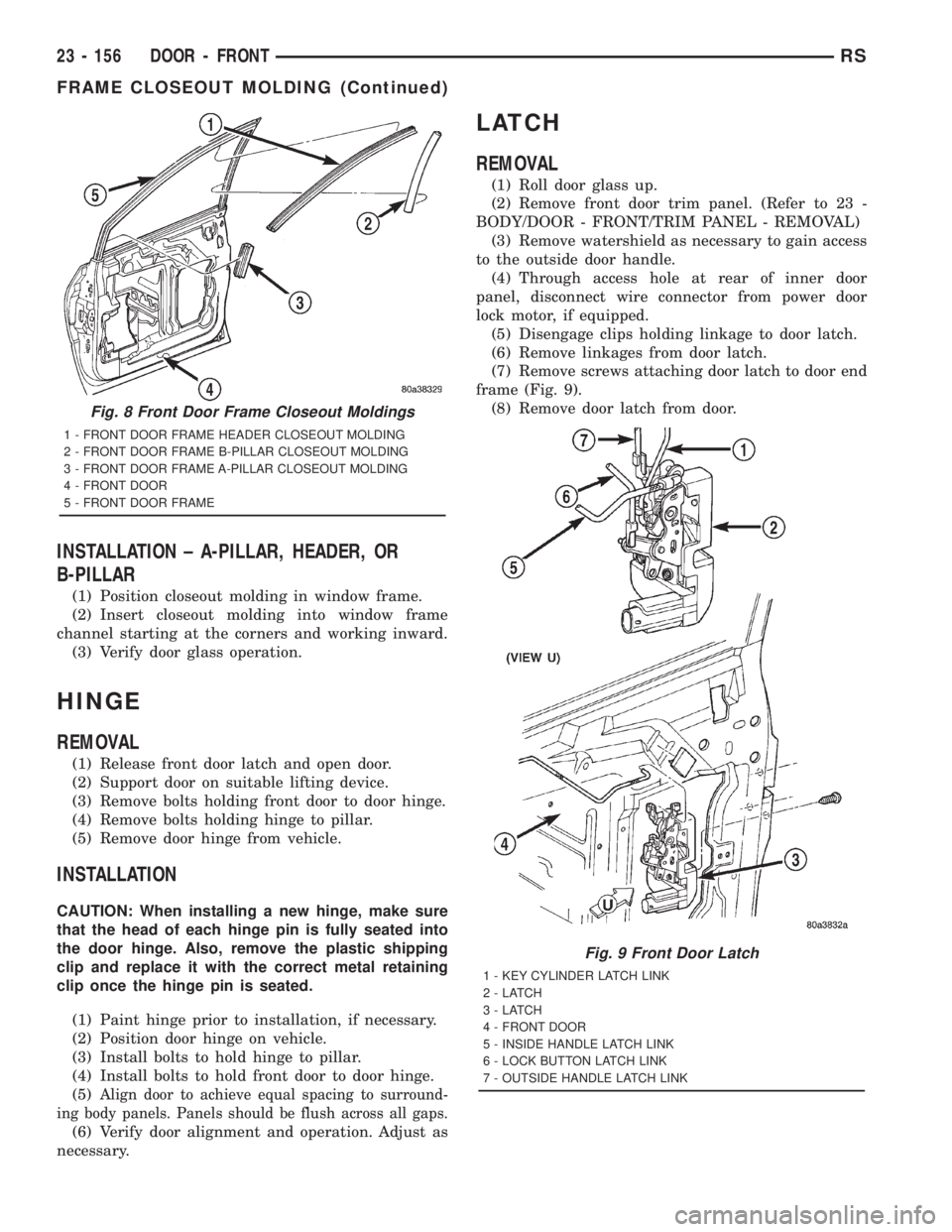
(2) Using a hook tool, pull front door frame close-
out molding from window frame channel (Fig. 8).
(3) Remove closeout molding from vehicle.
Fig. 6 Front Door Glass Clips
1 - DOOR GLASS
2 - GLASS LIFT PLATE
3 - CLIP
4 - GUIDE RAIL
5 - REGULATOR LIFT PLATE
Fig. 7 Front Door Glass
1 - DOOR GLASS
2 - FRONT DOOR
3 - GLASS RUN CHANNEL
RSDOOR - FRONT23 - 155
Page 3536 of 4284
INSTALLATION ± A-PILLAR, HEADER, OR
B-PILLAR
(1) Position closeout molding in window frame.
(2) Insert closeout molding into window frame
channel starting at the corners and working inward.
(3) Verify door glass operation.
HINGE
REMOVAL
(1) Release front door latch and open door.
(2) Support door on suitable lifting device.
(3) Remove bolts holding front door to door hinge.
(4) Remove bolts holding hinge to pillar.
(5) Remove door hinge from vehicle.
INSTALLATION
CAUTION: When installing a new hinge, make sure
that the head of each hinge pin is fully seated into
the door hinge. Also, remove the plastic shipping
clip and replace it with the correct metal retaining
clip once the hinge pin is seated.
(1) Paint hinge prior to installation, if necessary.
(2) Position door hinge on vehicle.
(3) Install bolts to hold hinge to pillar.
(4) Install bolts to hold front door to door hinge.
(5)
Align door to achieve equal spacing to surround-
ing body panels. Panels should be flush across all gaps.
(6) Verify door alignment and operation. Adjust as
necessary.
LATCH
REMOVAL
(1) Roll door glass up.
(2) Remove front door trim panel. (Refer to 23 -
BODY/DOOR - FRONT/TRIM PANEL - REMOVAL)
(3) Remove watershield as necessary to gain access
to the outside door handle.
(4) Through access hole at rear of inner door
panel, disconnect wire connector from power door
lock motor, if equipped.
(5) Disengage clips holding linkage to door latch.
(6) Remove linkages from door latch.
(7) Remove screws attaching door latch to door end
frame (Fig. 9).
(8) Remove door latch from door.
Fig. 8 Front Door Frame Closeout Moldings
1 - FRONT DOOR FRAME HEADER CLOSEOUT MOLDING
2 - FRONT DOOR FRAME B-PILLAR CLOSEOUT MOLDING
3 - FRONT DOOR FRAME A-PILLAR CLOSEOUT MOLDING
4 - FRONT DOOR
5 - FRONT DOOR FRAME
Fig. 9 Front Door Latch
1 - KEY CYLINDER LATCH LINK
2-LATCH
3-LATCH
4 - FRONT DOOR
5 - INSIDE HANDLE LATCH LINK
6 - LOCK BUTTON LATCH LINK
7 - OUTSIDE HANDLE LATCH LINK
23 - 156 DOOR - FRONTRS
FRAME CLOSEOUT MOLDING (Continued)
Page 3538 of 4284
(9) Verify door latch operation.
(10) Install watershield and door trim panel.
TRIM PANEL
REMOVAL
(1) Remove the plug and remove screw attaching
door pull cup to inner door panel.
(2) Remove screws attaching trim panel to door
from below map pocket.
(3) If equipped, remove window crank. (Refer to 23
- BODY/DOOR - FRONT/WINDOW CRANK -
REMOVAL)(4) Remove screw holding door trim to door panel
from behind inside latch release handle .
(5) Disengage clips attaching door trim to door
frame around perimeter of panel.
(6) Lift trim panel upward to disengage flange
from inner belt molding at top of door.
(7) Tilt top of trim panel away from door to gain
access to latch linkage.
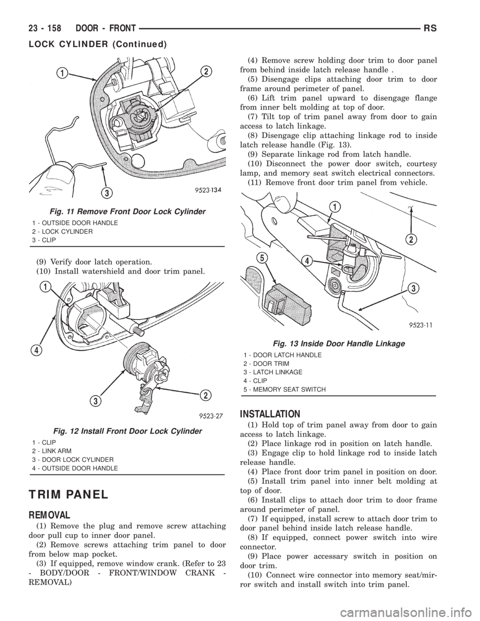
(8) Disengage clip attaching linkage rod to inside
latch release handle (Fig. 13).
(9) Separate linkage rod from latch handle.
(10) Disconnect the power door switch, courtesy
lamp, and memory seat switch electrical connectors.
(11) Remove front door trim panel from vehicle.
INSTALLATION
(1) Hold top of trim panel away from door to gain
access to latch linkage.
(2) Place linkage rod in position on latch handle.
(3) Engage clip to hold linkage rod to inside latch
release handle.
(4) Place front door trim panel in position on door.
(5) Install trim panel into inner belt molding at
top of door.
(6) Install clips to attach door trim to door frame
around perimeter of panel.
(7) If equipped, install screw to attach door trim to
door panel behind inside latch release handle.
(8) If equipped, connect power switch into wire
connector.
(9) Place power accessary switch in position on
door trim.
(10) Connect wire connector into memory seat/mir-
ror switch and install switch into trim panel.
Fig. 11 Remove Front Door Lock Cylinder
1 - OUTSIDE DOOR HANDLE
2 - LOCK CYLINDER
3 - CLIP
Fig. 12 Install Front Door Lock Cylinder
1 - CLIP
2 - LINK ARM
3 - DOOR LOCK CYLINDER
4 - OUTSIDE DOOR HANDLE
Fig. 13 Inside Door Handle Linkage
1 - DOOR LATCH HANDLE
2 - DOOR TRIM
3 - LATCH LINKAGE
4 - CLIP
5 - MEMORY SEAT SWITCH
23 - 158 DOOR - FRONTRS
LOCK CYLINDER (Continued)
Page 3539 of 4284
(11) Install screws to attach accessary switch
panel to door trim.
(12) Install screw cover into switch panel.
(13) If equipped, install window crank.
(14) If equipped, install screws to attach trim
panel to door inside map pocket.
(15) If equipped, install screw to attach door pull
cup to inner door panel.
(16) If equipped, install screws to attach door
assist handle to inner door panel.
(17) Connect wire connector into courtesy lamp.
(18) Install lamp in door trim.
TRIM PANEL REFLECTOR
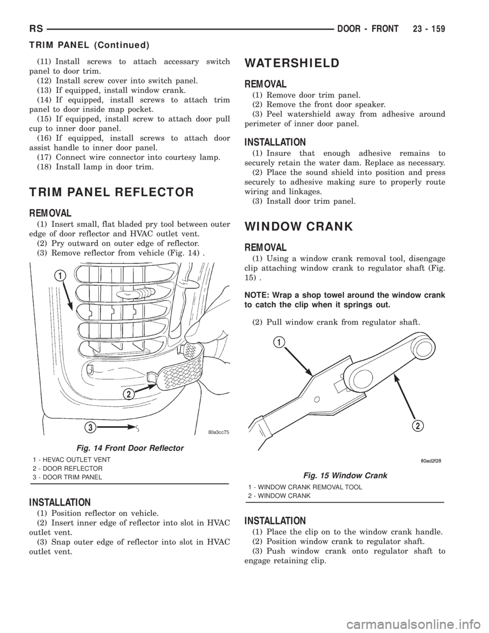
REMOVAL
(1) Insert small, flat bladed pry tool between outer
edge of door reflector and HVAC outlet vent.
(2) Pry outward on outer edge of reflector.
(3) Remove reflector from vehicle (Fig. 14) .
INSTALLATION
(1) Position reflector on vehicle.
(2) Insert inner edge of reflector into slot in HVAC
outlet vent.
(3) Snap outer edge of reflector into slot in HVAC
outlet vent.
WATERSHIELD
REMOVAL
(1) Remove door trim panel.
(2) Remove the front door speaker.
(3) Peel watershield away from adhesive around
perimeter of inner door panel.
INSTALLATION
(1) Insure that enough adhesive remains to
securely retain the water dam. Replace as necessary.
(2) Place the sound shield into position and press
securely to adhesive making sure to properly route
wiring and linkages.
(3) Install door trim panel.
WINDOW CRANK
REMOVAL
(1) Using a window crank removal tool, disengage
clip attaching window crank to regulator shaft (Fig.
15) .
NOTE: Wrap a shop towel around the window crank
to catch the clip when it springs out.
(2) Pull window crank from regulator shaft.
INSTALLATION
(1) Place the clip on to the window crank handle.
(2) Position window crank to regulator shaft.
(3) Push window crank onto regulator shaft to
engage retaining clip.
Fig. 14 Front Door Reflector
1 - HEVAC OUTLET VENT
2 - DOOR REFLECTOR
3 - DOOR TRIM PANEL
Fig. 15 Window Crank
1 - WINDOW CRANK REMOVAL TOOL
2 - WINDOW CRANK
RSDOOR - FRONT23 - 159
TRIM PANEL (Continued)
Page 3540 of 4284
WINDOW REGULATOR
REMOVAL
(1) Remove the watershield. (Refer to 23 - BODY/
DOOR - FRONT/WATERSHIELD - REMOVAL)
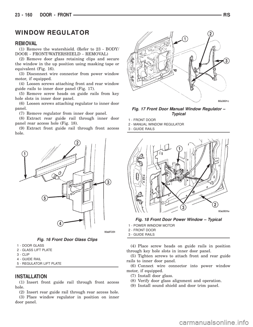
(2) Remove door glass retaining clips and secure
the window in the up position using masking tape or
equivalent (Fig. 16).
(3) Disconnect wire connector from power window
motor, if equipped.
(4) Loosen screws attaching front and rear window
guide rails to inner door panel (Fig. 17).
(5) Remove screw heads on guide rails from key
hole slots in inner door panel.
(6) Loosen screws attaching regulator to inner door
panel.
(7) Remove regulator from inner door panel.
(8) Extract rear guide rail through inner door
panel rear access hole (Fig. 18).
(9) Extract front guide rail through front access
hole.
INSTALLATION
(1) Insert front guide rail through front access
hole.
(2) Insert rear guide rail through rear access hole.
(3) Place window regulator in position on inner
door panel.(4) Place screw heads on guide rails in position
through key hole slots in inner door panel.
(5) Tighten screws to attach front and rear guide
rails to inner door panel.
(6) Connect wire connector into power window
motor, if equipped.
(7) Install door glass.
(8) Verify door glass alignment and operation.
(9) Install sound shield and door trim panel.
Fig. 16 Front Door Glass Clips
1 - DOOR GLASS
2 - GLASS LIFT PLATE
3 - CLIP
4 - GUIDE RAIL
5 - REGULATOR LIFT PLATE
Fig. 17 Front Door Manual Window Regulator ±
Typical
1 - FRONT DOOR
2 - MANUAL WINDOW REGULATOR
3 - GUIDE RAILS
Fig. 18 Front Door Power Window ± Typical
1 - POWER WINDOW MOTOR
2 - FRONT DOOR
3 - GUIDE RAILS
23 - 160 DOOR - FRONTRS
Page 3562 of 4284
(3) Disconnect liftgate wire harness from body
wire harness.
(4) Remove liftgate upper frame molding.
(5) Disconnect rear window washer hose from
spray nozzle.
(6) Support liftgate on a suitable lifting device.
(7) Remove screws attaching support cylinders to
liftgate.
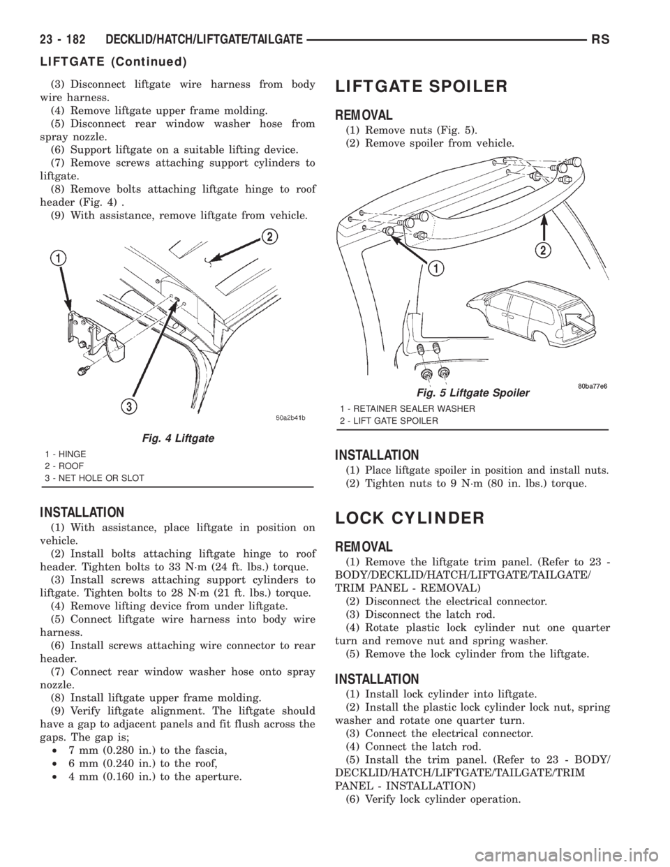
(8) Remove bolts attaching liftgate hinge to roof
header (Fig. 4) .
(9) With assistance, remove liftgate from vehicle.
INSTALLATION
(1) With assistance, place liftgate in position on
vehicle.
(2) Install bolts attaching liftgate hinge to roof
header. Tighten bolts to 33 N´m (24 ft. lbs.) torque.
(3) Install screws attaching support cylinders to
liftgate. Tighten bolts to 28 N´m (21 ft. lbs.) torque.
(4) Remove lifting device from under liftgate.
(5) Connect liftgate wire harness into body wire
harness.
(6) Install screws attaching wire connector to rear
header.
(7) Connect rear window washer hose onto spray
nozzle.
(8) Install liftgate upper frame molding.
(9) Verify liftgate alignment. The liftgate should
have a gap to adjacent panels and fit flush across the
gaps. The gap is;
²7 mm (0.280 in.) to the fascia,
²6 mm (0.240 in.) to the roof,
²4 mm (0.160 in.) to the aperture.
LIFTGATE SPOILER
REMOVAL
(1) Remove nuts (Fig. 5).
(2) Remove spoiler from vehicle.
INSTALLATION
(1)Place liftgate spoiler in position and install nuts.
(2) Tighten nuts to 9 N´m (80 in. lbs.) torque.
LOCK CYLINDER
REMOVAL
(1) Remove the liftgate trim panel. (Refer to 23 -
BODY/DECKLID/HATCH/LIFTGATE/TAILGATE/
TRIM PANEL - REMOVAL)
(2) Disconnect the electrical connector.
(3) Disconnect the latch rod.
(4) Rotate plastic lock cylinder nut one quarter
turn and remove nut and spring washer.
(5) Remove the lock cylinder from the liftgate.
INSTALLATION
(1) Install lock cylinder into liftgate.
(2) Install the plastic lock cylinder lock nut, spring
washer and rotate one quarter turn.
(3) Connect the electrical connector.
(4) Connect the latch rod.
(5) Install the trim panel. (Refer to 23 - BODY/
DECKLID/HATCH/LIFTGATE/TAILGATE/TRIM
PANEL - INSTALLATION)
(6) Verify lock cylinder operation.
Fig. 4 Liftgate
1 - HINGE
2 - ROOF
3 - NET HOLE OR SLOT
Fig. 5 Liftgate Spoiler
1 - RETAINER SEALER WASHER
2 - LIFT GATE SPOILER
23 - 182 DECKLID/HATCH/LIFTGATE/TAILGATERS
LIFTGATE (Continued)
Page 3584 of 4284
(17) Remove the two steering column shroud
retaining screws. Separate the shrouds and remove
from vehicle.
(18) Disconnect the steering column wiring. There
are seven connectors and then unclip the harness
from the column.
(19) Disconnect the ORC harness connector.
(20) Remove the four nuts retaining the steering
column and lower to the floor.
(21) Remove the four nuts attaching the instru-
ment panel to the brake pedal support bracket.
(22) Loosen the left side roll down bolt.
(23) Remove the left side A-pillar retaining bolts.
There are two 13 mm bolts and one 10 mm bolt.
(24) If equipped with a mechanical transmission
range indicator:
(a) Remove the indicator cable loop.
(b) Remove the clip holding gear shift cable end
to the gear selector adapter.
(c) Pull the cable end from gear selector.
(d) Disconnect the clip for the indicator cable
and guide tube from the shift cable bracket and
move out of the way.
(25) Remove the instrument panel top cover. Using
a trim stick or equivalent, gently pry up on the front
edge of the top cover, pull rearward and remove from
vehicle.
(26) Disconnect the right side wire connectors from
the HVAC behind the glove box area and the two
antenna connectors behind the glove box hinge.
(27) Remove the right end cover by pulling out-
board.
(28) Remove the right side A-pillar retaining bolts.
There are two 13 mm bolts and one 10 mm bolt.
(29) Loosen the right side roll down bolt.
(30) Disconnect the two front window defroster
grid wire connectors. One on each side of vehicle.
(31) Remove both the left and right power mirrors:
(a) Using a trim stick or equivalent, gently pry
out on mirror trim cover.
(b) Open door and remove the three torx retain-
ing screws.
(c) Disconnect the wire connector and remove
mirror from the vehicle.
(32) Feed power mirror wire harness inboard
through the A-pillar.
(33) Remove the bolts holding the instrument
panel frame to the dash panel below windshield
opening.
(34) With the help of an assistant remove the
instrument panel from vehicle. Lift the instrument
panel up off the HVAC so you won't damage the seal-
ing surface of the distribution duct.
If the instrument panel is being replaced, transfer
all parts to the new instrument panel assembly.INSTALLATION
(1) With the help of an assistant place the instru-
ment panel into vehicle on roll down bolts. As you
roll the instrument panel up, lift the instrument
panel up so the duct work does not bind or bend and
you can set it down on the HVAC housing to get the
proper seal at the distribution duct. Get one bolt
started in the dash panel.
(2) Install the bolts holding the instrument panel
frame to the dash panel below windshield opening.
(3) Feed power mirror wire harness outboard
through the A-pillar.
(4) Install both the left and right power mirrors:
(a) Connect the wire connector and install the
mirror onto the vehicle.
(b) Install the three torx retaining screws.
(c) Using a firm push, snap the mirror trim
cover into place.
(5) Connect the two front window defroster grid
wire connectors. One on each side of vehicle.
(6) Tighten the right side roll down bolt.
(7) Install the right side A-pillar retaining bolts.
There are two 13 mm bolts and one 10 mm bolt.
(8) Install the right end cover. Position over retain-
ing slots and firmly snap into place.
(9) Connect the right side wire connectors to the
HVAC behind the glove box area and the two
antenna connectors behind the glove box hinge.
(10) Install the instrument panel top cover. Slide
the front edge of the top cover toward dash panel,
and firmly snap down the rear edge of the to cover to
engage clips.
(11) If equipped with a mechanical transmission
range indicator:
(a) Connect the clip for the indicator cable and
guide tube to the shift cable bracket.
(b) Install the cable end to the gear selector.
(c) Install the clip holding the gear shift cable
end to the gear selector adapter.
(d) Install the indicator cable loop.
(12) Install the left side A-pillar retaining bolts.
There are two 13 mm bolts and one 10 mm bolt.
(13) Tighten the left side roll down bolt.
(14) Install the four nuts attaching the instrument
panel to the brake pedal support bracket.
(15) Install the four nuts retaining the steering
column and lower to the floor.
(16) Connect the ORC harness connector.
(17) Connect the steering column wiring. There
are seven connectors and then clip the harness to the
column.
(18) Connect the shrouds and install the two steer-
ing column shroud retaining screws.
(19) Install five screws to the left under column
instrument panel reinforcement brace.
23 - 204 INSTRUMENT PANELRS
INSTRUMENT PANEL ASSEMBLY (Continued)
Page 3623 of 4284
STATIONARY GLASS
TABLE OF CONTENTS
page page
WINDSHIELD
DESCRIPTION..........................243
WARNING.............................243
REMOVAL.............................243
INSTALLATION..........................244
SLIDING DOOR GLASS
REMOVAL.............................245INSTALLATION..........................245
QUARTER WINDOW
REMOVAL.............................246
INSTALLATION..........................246
REAR DOOR GLASS
REMOVAL.............................246
INSTALLATION..........................246
WINDSHIELD
DESCRIPTION
The windshield is attached to the window frame
with urethane adhesive. The urethane adhesive is
applied cold and seals the surface area between the
window opening and the glass. The primer adheres
the urethane adhesive to the windshield.
It is difficult to salvage a windshield during the
removal operation. The windshield is part of the
structural support for the roof. The urethane bonding
used to secure the windshield to the fence is difficult
to cut or clean from any surface. If the moldings are
set in urethane, it would also be unlikely they could
be salvaged. Before removing the windshield, check
the availability of the windshield and moldings from
the parts supplier.
WINDSHIELD SAFETY PRECAUTIONS
WARNING: DO NOT OPERATE THE VEHICLE
WITHIN 24 HOURS OF WINDSHIELD INSTALLATION.
IT TAKES AT LEAST 24 HOURS FOR URETHANE
ADHESIVE TO CURE. IF IT IS NOT CURED, THE
WINDSHIELD MAY NOT PERFORM PROPERLY IN
AN ACCIDENT.
URETHANE ADHESIVES ARE APPLIED AS A SYS-
TEM. USE GLASS CLEANER, GLASS PREP SOL-
VENT, GLASS PRIMER, PVC (VINYL) PRIMER AND
PINCH WELD (FENCE) PRIMER PROVIDED BY THE
ADHESIVE MANUFACTURER. IF NOT, STRUCTURAL
INTEGRITY COULD BE COMPROMISED.
DAIMLERCHRYSLER DOES NOT RECOMMEND
GLASS ADHESIVE BY BRAND. TECHNICIANS
SHOULD REVIEW PRODUCT LABELS AND TECHNI-
CAL DATA SHEETS, AND USE ONLY ADHESIVES
THAT THEIR MANUFACTURES WARRANT WILL
RESTORE A VEHICLE TO THE REQUIREMENTS OF
FMVSS 212. TECHNICIANS SHOULD ALSO INSURE
THAT PRIMERS AND CLEANERS ARE COMPATIBLEWITH THE PARTICULAR ADHESIVE USED.
BE SURE TO REFER TO THE URETHANE MANU-
FACTURER'S DIRECTIONS FOR CURING TIME
SPECIFICATIONS, AND DO NOT USE ADHESIVE
AFTER ITS EXPIRATION DATE.
VAPORS THAT ARE EMITTED FROM THE URE-
THANE ADHESIVE OR PRIMER COULD CAUSE
PERSONAL INJURY. USE THEM IN A WELL-VENTI-
LATED AREA.
SKIN CONTACT WITH URETHANE ADHESIVE
SHOULD BE AVOIDED. PERSONAL INJURY MAY
RESULT.
ALWAYS WEAR EYE AND HAND PROTECTION
WHEN WORKING WITH GLASS.
CAUTION: Protect all painted and trimmed surfaces
from coming in contact with urethane or primers.
Be careful not to damage painted surfaces when
removing moldings or cutting urethane around
windshield.
REMOVAL
WINDSHIELD REMOVAL ± EXTERIOR METHOD
The urethane adhesive holding the windshield to
the opening pinch weld (fence) can be cut using a
sharp cold knife from the exterior of the vehicle.
Using the cold knife method is effective if the wind-
shield is already broken. If the glass must be sal-
vaged, cutting the urethane adhesive from the
interior of the vehicle using a reciprocating or oscil-
lating power knife is recommended.
(1) Remove inside rear view mirror.
(2) Remove windshield wiper arms.
(3) Remove cowl cover.
(4) Remove A-pillar trim panels.
(5) Disconnect wire connectors to windshield
defroster grid.
RSSTATIONARY GLASS23 - 243
Page 3626 of 4284
(4) Install interior trim. (Refer to 23 - BODY/
DOORS - SLIDING/TRIM PANEL - INSTALLATION)
(5) Verify alignment and flushness.
QUARTER WINDOW
REMOVAL
(1) Remove C-pillar trim.
(2) Open quarter glass to vent position.
(3) Disengage quarter window retainer from vent
motor arm.
(4) Remove nuts attaching quarter glass to C-pillar
(Fig. 5) .
(5) Use magnetic socket to prevent dropping into
the pillar.
(6) Remove quarter glass from vehicle.
INSTALLATION
(1) Place quarter glass in position on vehicle.
(2) Install nuts attaching quarter glass to C-pillar.
(3) Engage quarter window retainer to vent motor
arm.
(4) Install screw attaching quarter window
retainer to vent motor arm.
(5) Close quarter glass.
(6) Install C-pillar trim.
REAR DOOR GLASS
REMOVAL
Refer to the Safety Precautions in this section for
description of tools and adhesive systems that are
recommended for use in this procedure.
REAR WINDOW REMOVAL ± EXTERIOR METHOD
(1) Remove rear window wiper arm, if equipped.
(2) Remove screws attaching moldings to liftgate
at the sides of the rear window (Fig. 6).
(3) Using pliers, pull outward on molding at the
top and bottom of liftgate.
(4) Using a sharp cold knife, cut urethane adhe-
sive attaching the rear window to the liftgate. A
power cutting device can be used if available (Fig. 1).
(5) Remove rear window from vehicle.
REAR WINDOW REMOVAL ± INTERIOR METHOD
(1) Remove rear window wiper arm, if equipped.
(2) Remove screws attaching moldings to liftgate
at the sides of the rear window (Fig. 6).
(3) Remove liftgate inside lamps and trim covers.
(4) Remove center high mounted stop lamp.
(5) Using a reciprocating or oscillating power
knife, cut urethane adhesive holding the rear window
to the liftgate. Refer to instructions provided with
the equipment being used.
(6) Remove rear window from vehicle.
INSTALLATION
Refer to the Safety Precautions in this section for
description of tools and adhesive systems that are
recommended for use in this procedure.
Fig. 5 Quarter Glass
1 - VENT CONTROL
2 - QUARTER GLASS
3 - CLIP
Fig. 6 Rear Window Side Moldings
1 - COMPRESSION SPACERS
2 - REAR WINDOW WITH MOLDING
3 - LIFT GATE
23 - 246 STATIONARY GLASSRS
SLIDING DOOR GLASS (Continued)