tow Citroen C4 2015 2.G Service Manual
[x] Cancel search | Manufacturer: CITROEN, Model Year: 2015, Model line: C4, Model: Citroen C4 2015 2.GPages: 494, PDF Size: 20.49 MB
Page 244 of 494
242
C4-2_en_Chap11_info-pratique_ed01-2015
C4-2_en_Chap11_info-pratique_ed01-2015
Changing a bulb
The headlamps are fitted with polycarbonate glass with a protective
c
oating:
F
d
o not clean them using a dr y
or abrasive cloth, nor with a
detergent or solvent product,
F
u
se a sponge and soapy water or a
p
H neutral product,
F
w
hen using a high pressure washer
o
n persistent marks, do not keep
t
he lance directed towards the
lamps
or their edges for too long,
s
o as not to damage their protective
c
oating
a
nd
sea
ls.
Changing
a bulb should only be done
a
fter the headlamp has been switched
o
ff for several minutes (risk of serious
b
urns).
F
d
o n
ot touch the bulb directly with
your
fingers, use a lint-free cloth.
It
is imperative to use only anti-
ultraviolet
(UV) type bulbs to avoid
d
amaging
t
he
h
eadlamp.
al
ways replace a failed bulb with a
new
bulb with the same type and
s
pecification.Front lamps
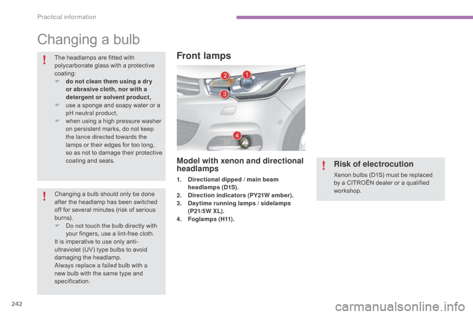
Model with xenon and directional
headlamps
1. Directional dipped / main beam headlamps (D1S).
2.
D
irection indicators (PY21W amber).
3.
D
aytime running lamps / sidelamps
(P21/5W XL).
4.
F
o g l a m p s ( H11) .
Risk of electrocution
Xenon bulbs (D1S) must be replaced by a CITROËN dealer or a qualified
w
orkshop.
Practical information
Page 249 of 494
247
C4-2_en_Chap11_info-pratique_ed01-2015
C4-2_en_Chap11_info-pratique_ed01-2015
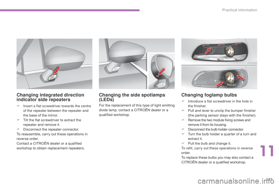
Changing foglamp bulbs
F Introduce a flat screwdriver in the hole in the f inisher.
F
P
ull and lever to unclip the bumper finisher
(
the parking sensor stays with the finisher).
F
R
emove the two module fixing screws and
r
emove it from its housing.
F
D
isconnect the bulb holder connector.
F
T
urn the bulb holder a quarter of a turn and
e
xtract it.
F
P
ull the bulb and change it.
To refit, carry out these operations in reverse
o r d e r.
To
replace these bulbs you may also contact a
C
ITROËN dealer or a qualified workshop.
Changing the side spotlamps
(LEDs)
For the replacement of this type of light emitting diode lamp, contact a CITROËN dealer or a
q
ualified
w
orkshop.
Changing integrated direction
indicator side repeaters
F Insert a flat screwdriver towards the centre of the repeater between the repeater and
the
base of the mirror.
F
T
ilt the flat screwdriver to extract the
r
epeater and remove it.
F
D
isconnect the repeater connector.
To
reassemble, carry out these operations in
r
everse
o
rder.
Contact
a CITROËN dealer or a qualified
w
orkshop to obtain replacement repeaters.
11
Practical information
Page 250 of 494
248
C4-2_en_Chap11_info-pratique_ed01-2015
C4-2_en_Chap11_info-pratique_ed01-2015
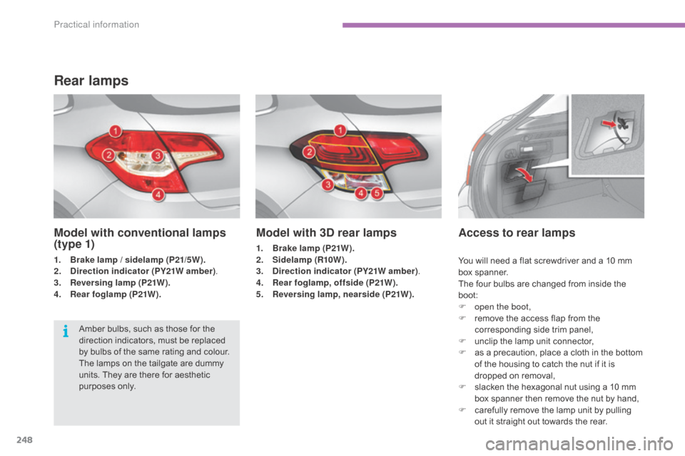
Model with 3D rear lamps
1. Brake lamp (P21W).
2. Sidelamp (R10W ).
3.
D
irection indicator (PY21W amber) .
4.
R
ear foglamp, offside (P21W).
5.
R
eversing lamp, nearside (P21W).
Access to rear lamps
Amber bulbs, such as those for the direction indicators, must be replaced
b
y bulbs of the same rating and colour.
The
lamps on the tailgate are dummy
u
nits. They are there for aesthetic
p
urposes only.
Rear lamps
Model with conventional lamps
(t y p e 1)
1. Brake lamp / sidelamp (P21/5W).
2. Direction indicator (PY21W amber) .
3.
R
eversing lamp (P21W).
4.
R
ear foglamp (P21W). You
will need a flat screwdriver and a 10 mm
b
ox
span
ner.
The
four bulbs are changed from inside the
b
oot:
F
o
pen the boot,
F
r
emove the access flap from the
c
orresponding side trim panel,
F
u
nclip the lamp unit connector,
F
a
s a precaution, place a cloth in the bottom
o
f the housing to catch the nut if it is
d
ropped on removal,
F
s
lacken the hexagonal nut using a 10 mm
b
ox spanner then remove the nut by hand,
F
c
arefully remove the lamp unit by pulling
o
ut it straight out towards the rear.
Practical information
Page 264 of 494
262
C4-2_en_Chap11_info-pratique_ed01-2015
C4-2_en_Chap11_info-pratique_ed01-2015
Very cold climate screen*
* According to country.
Fitting
F Offer up the very cold climate screen to t
he front of the lower section of the front
b u m p e r.
F
P
ress around its edge to engage its fixing
c
lips one by one.
Removal
F Use a screwdriver as a lever to release e
ach fixing clip in turn.
Removable
protective screen which prevents
t
he accumulation of snow at the radiator
c
ooling fan.
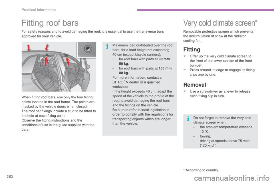
Fitting roof bars
For safety reasons and to avoid damaging the roof, it is essential to use the transverse bars a
pproved for your vehicle.
When
fitting roof bars, use only the four fixing
p
oints located in the roof frame. The points are
m
asked by the vehicle doors when closed.
The
roof bar fixings include a stud to be fitted to
t
he hole at each fixing point.
Observe
the fitting instructions and the
c
onditions of use in the guide supplied with the
b
ars. Do
not forget to remove the very cold
c
limate screen when:
-
t
he ambient temperature exceeds
1
0 °C,
-
tow
ing,
-
d
riving at speeds above 75 mph
(
120 km/h).
Maximum
load distributed over the roof
b
ars, for a load height not exceeding
4
0 cm (except bicycle carriers):
-
f
or roof bars with pads at 90 mm:
5
0 kg,
-
f
or roof bars with pads at 15 0
mm:
8
0 kg.
For
more information, contact a
C
ITROËN dealer or a qualified
w
orkshop.
If
the height exceeds 40 cm, adapt the
s
peed of the vehicle to the profile of the
road
to avoid damaging the roof bars
a
nd the fixings on the vehicle.
Be
sure to refer to local legislation in
o
rder to comply with the regulations for
t
ransporting objects which are longer
t
han the vehicle.
Practical information
Page 265 of 494
263
C4-2_en_Chap11_info-pratique_ed01-2015
C4-2_en_Chap11_info-pratique_ed01-2015
Towing the vehicle
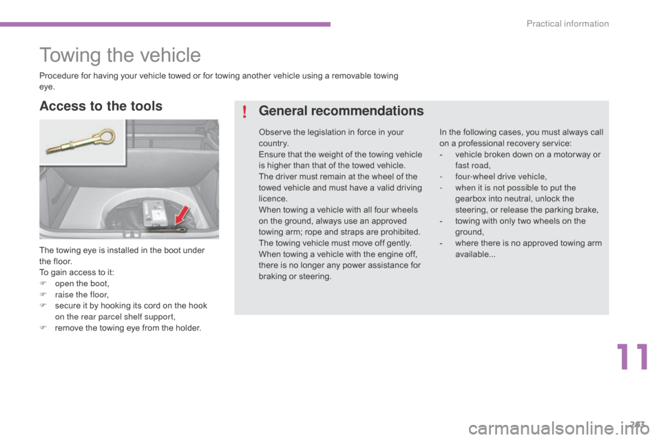
The towing eye is installed in the boot under the floor.
To
gain access to it:
F
o
pen the boot,
F
r
aise the floor,
F
s
ecure it by hooking its cord on the hook
o
n the rear parcel shelf
s
upport,
F
r
emove the towing eye from the holder.
Access to the tools General recommendations
In the following cases, you must always call o
n a professional recovery service:
-
v
ehicle broken down on a motor way or
f
ast road,
-
f
our-wheel drive vehicle,
-
w
hen it is not possible to put the
gearbox
into neutral, unlock the
s
teering, or release the parking brake,
-
t
owing with only two wheels on the
g
round,
-
w
here there is no approved towing arm
a
vailable...
Procedure
for
having
your
vehicle
towed
or
for
towing
another
vehicle
using
a
removable
towing
ey
e.
Observe
the
legislation
in
force
in
your
c
o unt r y.
Ensure
that
the
weight
of
the
towing
vehicle
i
s
higher
than
that
of
the
towed
vehicle.
The
driver
must
remain
at
the
wheel
of
the
t
owed
vehicle
and
must
have
a
valid
driving
l
icence.
When
towing
a
vehicle
with
all
four
wheels
o
n
the
ground,
always
use
an
approved
t
owing
arm;
rope
and
straps
are
prohibited.
The
towing
vehicle
must
move
off
gently.
When
towing
a
vehicle
with
the
engine
off,
t
here
is
no
longer
any
power
assistance
for
b
raking
or
steering.
11
Practical information
Page 266 of 494
264
C4-2_en_Chap11_info-pratique_ed01-2015
C4-2_en_Chap11_info-pratique_ed01-2015
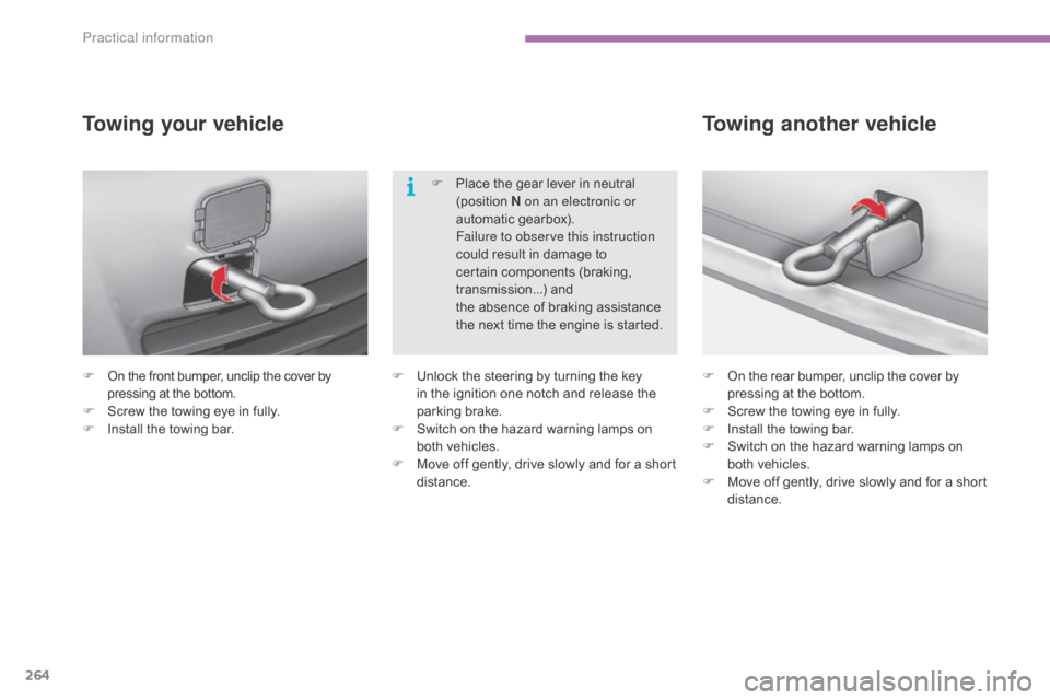
F On the front bumper, unclip the cover by p
ressing at the bottom.
F
S
crew the towing eye in fully.
F
I
nstall the towing bar.
Towing your vehicle
F On the rear bumper, unclip the cover b y p
ressing at the bottom.
F
S
crew the towing eye in fully.
F
I
nstall the towing bar.
F
S
witch on the hazard warning lamps on
b
oth vehicles.
F
M
ove off gently, drive slowly and for a short
di
stance.
Towing another vehicle
F Unlock the steering by turning the key i
n the ignition one notch and release the
par
king
b
rake.
F
S
witch on the hazard warning lamps on
b
oth vehicles.
F
M
ove off gently, drive slowly and for a short
di
stance.F
P
lace the gear lever in neutral
(
position
N
on an electronic or
automatic gearbox).
F
ailure to observe this instruction
could result in damage to
c
ertain components (braking,
t
ransmission...) and
the absence of braking assistance
t
he next time the engine is started.
Practical information
Page 267 of 494
265
C4-2_en_Chap11_info-pratique_ed01-2015
C4-2_en_Chap11_info-pratique_ed01-2015
Towing a trailer
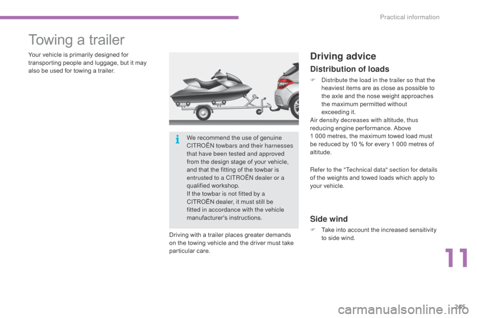
Your vehicle is primarily designed for transporting people and luggage, but it may
a
lso be used for towing a trailer.
Driving
with a trailer places greater demands
o
n the towing vehicle and the driver must take
par
ticular
c
are.Driving advice
Distribution of loads
F distribute the load in the trailer so that the heaviest items are as close as possible to
t
he axle and the nose weight approaches
t
he maximum permitted without
e
xceeding it.
ai
r density decreases with altitude, thus
reducing
engine per formance. Above
1 0
00 metres, the maximum towed load must
b
e reduced by 10 % for every 1 000 metres of
al
titude.
Side wind
F Take into account the increased sensitivity t
o side wind.
Refer to the "Technical data" section for details
of
the weights and towed loads which apply to
y
our vehicle.
We
recommend
the
use
of
genuine
C
ITR
oËn
towbars and their harnesses
that have been tested and approved
from
the
design
stage
of
your
vehicle,
a
nd
that
the
fitting
of
the
towbar
is
e
ntrusted to a CITR
oËn
dealer or a
qualified
w
orkshop.
If the towbar is not fitted by a
CITROËN
dealer,
it
must
still
be
f
itted in accordance with the vehicle
manufacturer's
i
nstructions.
11
Practical information
Page 268 of 494
266
C4-2_en_Chap11_info-pratique_ed01-2015
C4-2_en_Chap11_info-pratique_ed01-2015
F If the warning lamp and the S
TOP warning lamp come on,
s
top the vehicle and switch off
the
engine as soon as possible.
Braking
Towing a trailer increases the braking distance.
T o avoid overheating of the brakes on a long
m
ountain type of descent, the use of engine
b
raking is recommended.
Ty r e s
F Check the tyre pressures of the
towing vehicle and of the trailer, observing
t
he
re
commended
p
ressures.
Lighting
F Check the electrical lighting and signalling o
n the trailer.
The
rear parking sensors will be
d
eactivated automatically if a genuine
C
ITROËN towbar is used.
Cooling
Towing a trailer on a slope increases the temperature of the coolant.
As
the fan is electrically controlled, its cooling
c
apacity is not dependent on the engine speed.
F
T
o lower the engine speed, reduce your
s
peed.
The
maximum towed load on a long incline
d
epends on the gradient and the ambient
t
emperature.
In
all cases, keep a check on the
c
oolant
t
emperature.
Practical information
Page 269 of 494
267
C4-2_en_Chap11_info-pratique_ed01-2015
C4-2_en_Chap11_info-pratique_ed01-2015
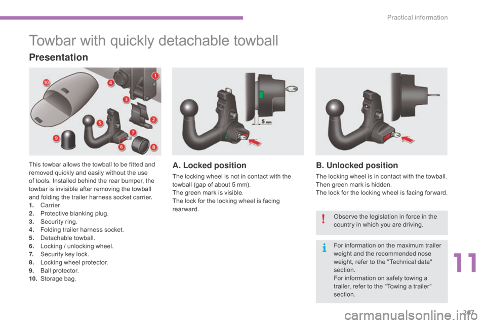
Towbar with quickly detachable towball
Presentation
This towbar allows the towball to be fitted and
removed quickly and easily without the use
o
f tools. Installed behind the rear bumper, the
t
owbar is invisible after removing the towball
a
nd folding the trailer harness socket carrier.
1.
Carrier
2.
P
rotective blanking plug.
3.
S
ecurity ring.
4.
F
olding trailer harness socket.
5.
D
etachable
t
owball.
6.
L
ocking / unlocking wheel.
7.
S
ecurity key lock.
8.
L
ocking wheel protector.
9.
Ba
ll
pro
tector.
10.
St
orage
b
ag.A. Locked position
The locking wheel is not in contact with the towball (gap of about 5 mm).
The
green mark is visible.
The
lock for the locking wheel is facing
r
earward.
B. Unlocked position
The locking wheel is in contact with the towball.
T hen green mark is hidden.
The
lock for the locking wheel is facing for ward.
Observe
the legislation in force in the
c
ountry in which you are driving.
For
information on the maximum trailer
w
eight and the recommended nose
w
eight, refer to the "Technical data"
s
ection.
For
information on safely towing a
t
railer, refer to the "Towing a trailer"
s
ection.
11
Practical information
Page 270 of 494
268
C4-2_en_Chap11_info-pratique_ed01-2015
C4-2_en_Chap11_info-pratique_ed01-2015
Before each use
Check that the towball is correctly fitted by verifying the following points:
- t he towball is correctly locked in place (position A),
-
t
he security key lock is on and the key removed; the locking wheel can no longer be
ope
rated,
-
t
he towball must no longer move at all in its carrier; try to shake it by hand.
During use
Never unlock the device when a trailer or load carrier is fitted to the towball.
N ever exceed the maximum authorised weight for the vehicle plus trailer (Gross Train
W
eight - GTW).
After use
For journeys made without a trailer or load carrier, the trailer harness socket must be folded away, the towball removed and the blanking plug inserted in the carrier. This measure
a
pplies particularly if the towball could hinder visibility of the number plate or lighting.
Practical information