CITROEN C6 2005 Owners Manual
Manufacturer: CITROEN, Model Year: 2005, Model line: C6, Model: CITROEN C6 2005Pages: 223, PDF Size: 4.26 MB
Page 101 of 223
![CITROEN C6 2005 Owners Manual Downloaded from www.Manualslib.com manuals search engine 95
INJECTION
CHECKS: TURBO PRESSURE
Engine: DT17BTED4
Tools.
[1]Pressure gauge for checking the pressure: 7073-T.A
[2]Tool for checking the inl CITROEN C6 2005 Owners Manual Downloaded from www.Manualslib.com manuals search engine 95
INJECTION
CHECKS: TURBO PRESSURE
Engine: DT17BTED4
Tools.
[1]Pressure gauge for checking the pressure: 7073-T.A
[2]Tool for checking the inl](/img/9/57744/w960_57744-100.png)
Downloaded from www.Manualslib.com manuals search engine 95
INJECTION
CHECKS: TURBO PRESSURE
Engine: DT17BTED4
Tools.
[1]Pressure gauge for checking the pressure: 7073-T.A
[2]Tool for checking the inlet air pressure/vacuum: (-).0171.G3
[3] LEXIAdiagnostic tool: 4171-T
[4] PROXIAdiagnostic tool: 4165-T
Checks.
IMPERATIVE: Respect the safety and cleanliness specific to high pressure diesel injection
engines.
Preliminary operations.
WARNING: Prior to any intervention, check the connections of the turbocharger pressure
regulation actuators.
NOTE:If an air flow fault is memorised by the diagnostic tool, refer to the chapter "Air flow from
the turbochargers".
Turbo pressure sensor.
Remove the engine cover.
Disconnect the connector "a".
Remove the turbo pressure sensor (1).
B1BP3CZC
Angl-C6-page83-100-2005 4/02/05 17:22 Page 95
Page 102 of 223
![CITROEN C6 2005 Owners Manual Downloaded from www.Manualslib.com manuals search engine 96
INJECTION
CHECKS: TURBO PRESSURE
Engine: DT17BTED4
Connect:
- The tool [2a]in place of the turbo pressure sensor (1).
- The turbo pressure s CITROEN C6 2005 Owners Manual Downloaded from www.Manualslib.com manuals search engine 96
INJECTION
CHECKS: TURBO PRESSURE
Engine: DT17BTED4
Connect:
- The tool [2a]in place of the turbo pressure sensor (1).
- The turbo pressure s](/img/9/57744/w960_57744-101.png)
Downloaded from www.Manualslib.com manuals search engine 96
INJECTION
CHECKS: TURBO PRESSURE
Engine: DT17BTED4
Connect:
- The tool [2a]in place of the turbo pressure sensor (1).
- The turbo pressure sensor (1)on the tool [2b].
- Tool [1]on tool [2], at "b".
Connect the diagnostic tool [3]or [4]to the vehicle's diagnostic socket:
- Put the diagnostic tool [3]or [4]in parameter measures.
Start the engine.
Accelerate to 2500 rpm.
Compare the pressure values read on the diagnostic tool and on the pressure gauge [1].
NOTE:If there is a significant difference in pressure, replace the turbo pressure sensor.
Air/air exhanger.
Check the condition of the following components:
- Air inlet pipe.
- Airoutlet pipe.
- Air /air exchanger.
Air flow from the turbochargers.
NOTE: If an air flow fault is memorised by the diagnostic tool, check the air flow from the turbocharger
incriminated.
Connect the diagnostic tool [3]or [4]to the vehicle's diagnostic socket:
- Put the diagnostic tool [3]or [4]in parameter measures.
Start the engine.
Accelerate to 2500 rpm.
Compare the air flows (mg/stroke)from the two turbochargers.
B1BP3D0C
Angl-C6-page83-100-2005 4/02/05 17:22 Page 96
Page 103 of 223
Downloaded from www.Manualslib.com manuals search engine 97
INJECTION
CHECKS: TURBO PRESSURE
Engine: DT17BTED4
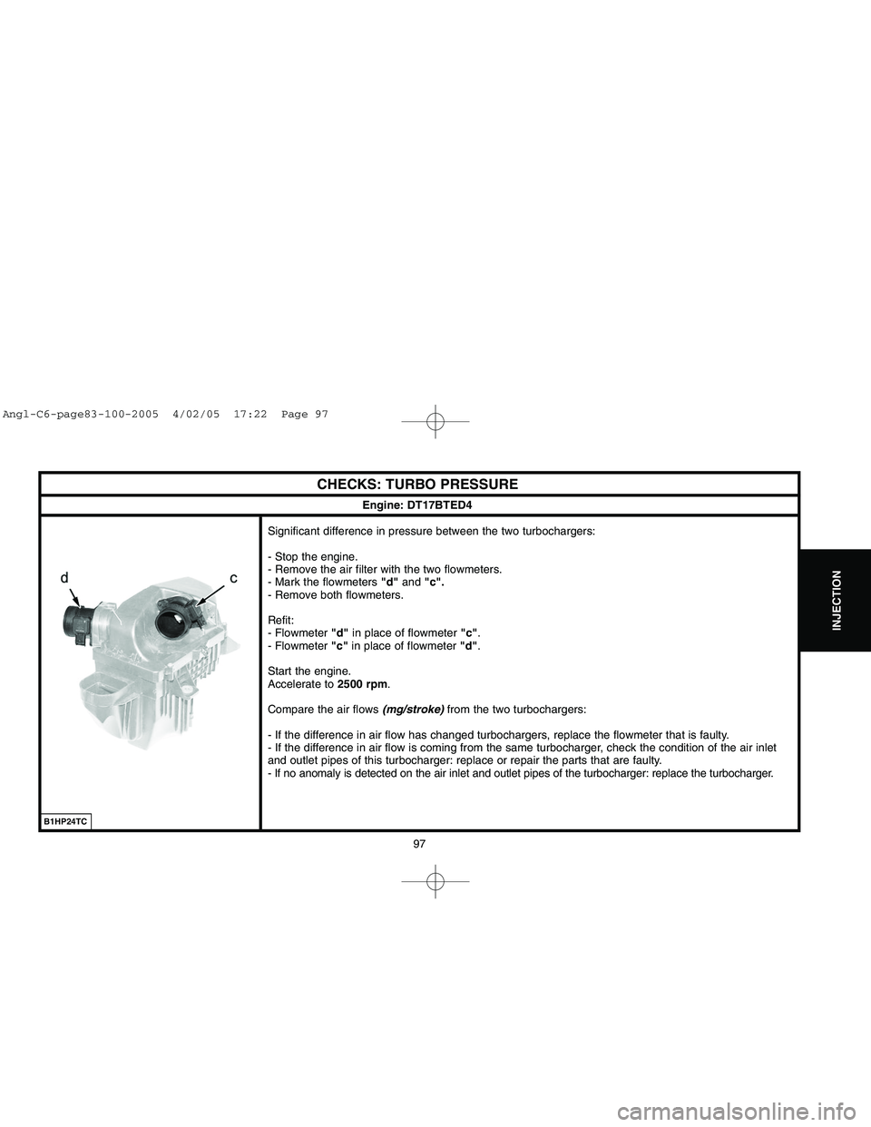
Significant difference in pressure between the two turbochargers:
- Stop the engine.
- Remove the air filter with the two flowmeters.
- Mark the flowmeters "d"and "c".
- Remove both flowmeters.
Refit:
- Flowmeter "d"in place of flowmeter "c".
- Flowmeter "c"in place of flowmeter "d".
Start the engine.
Accelerate to 2500 rpm.
Compare the air flows (mg/stroke)from the two turbochargers:
- If the difference in air flow has changed turbochargers, replace the flowmeter that is faulty.
- If the difference in air flow is coming from the same turbocharger, check the condition of the air inlet
and outlet pipes of this turbocharger: replace or repair the parts that are faulty.
- If no anomaly is detected on the air inlet and outlet pipes of the turbocharger: replace the turbocharger.
B1HP24TC
Angl-C6-page83-100-2005 4/02/05 17:22 Page 97
Page 104 of 223
Downloaded from www.Manualslib.com manuals search engine 98
INJECTION
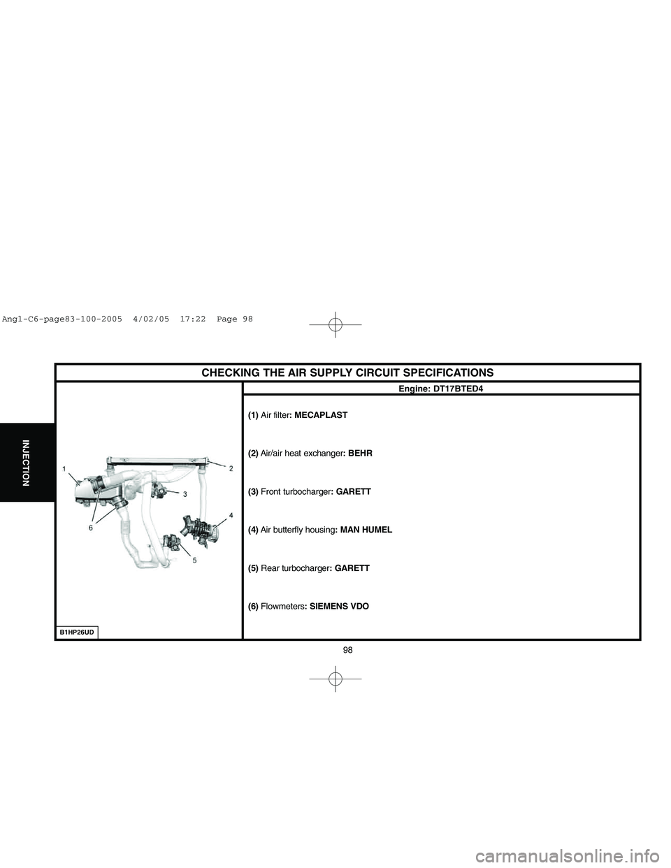
CHECKING THE AIR SUPPLY CIRCUIT SPECIFICATIONS
Engine: DT17BTED4
(1) Air filter: MECAPLAST
(2)Air/air heat exchanger: BEHR
(3) Front turbocharger: GARETT
(4)Air butterfly housing: MAN HUMEL
(5)Rear turbocharger: GARETT
(6)Flowmeters: SIEMENS VDO
B1HP26UD
Angl-C6-page83-100-2005 4/02/05 17:22 Page 98
Page 105 of 223
![CITROEN C6 2005 Owners Manual Downloaded from www.Manualslib.com manuals search engine 99
INJECTION
CHECKING THE AIR SUPPLY CIRCUIT
Tool.
[1]Manual pressure-vacuum pump : FACOM DA 16
Checks.
IMPERATIVE: Respect the safety and clea CITROEN C6 2005 Owners Manual Downloaded from www.Manualslib.com manuals search engine 99
INJECTION
CHECKING THE AIR SUPPLY CIRCUIT
Tool.
[1]Manual pressure-vacuum pump : FACOM DA 16
Checks.
IMPERATIVE: Respect the safety and clea](/img/9/57744/w960_57744-104.png)
Downloaded from www.Manualslib.com manuals search engine 99
INJECTION
CHECKING THE AIR SUPPLY CIRCUIT
Tool.
[1]Manual pressure-vacuum pump : FACOM DA 16
Checks.
IMPERATIVE: Respect the safety and cleanliness specific to high pressure
diesel injection engines.
Checking the vacuum source (vacuum pump).
Connect the tool [1]on the take-off "a"of the vacuum pump (1).
Start the engine.
The value should be 0,85 ± 0,2 bar.
"Swirl" control electrovalve.
Connect the tool [1]on the vacuum supply "b"of the electrovalve (2).
Start the engine.
The value should be 0,85 ± 0,2 bar.
"Swirl" control diaphragm.
Connect the tool [1]on the "Swirl"control diaphragms (3)at "c".
Apply a vacuum of approx. 0,7 ± 0,2 bar, the "Swirl"butterfly should be fully
open.
Engine: DT17BTED4
B1HP26ECB1HP26DC
B1HP26FC
Angl-C6-page83-100-2005 4/02/05 17:22 Page 99
Page 106 of 223
Downloaded from www.Manualslib.com manuals search engine 100
IGNITION
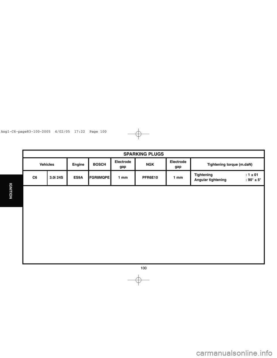
Vehicles Engine BOSCHElectrode
NGKElectrode
Tightening torque (m.daN)
gap gap
C6 3.0i 24S ES9A FGR8MQPE 1 mm PFR6E10 1 mmTightening : 1 ± 01
Angular tightening : 90° ± 5°
SPARKING PLUGS
Angl-C6-page83-100-2005 4/02/05 17:22 Page 100
Page 107 of 223

Downloaded from www.Manualslib.com manuals search engine 101
CLUTCH
GEARBOX
TRANSMISSION
SPEEDOMETER
An E.E.C. decree of 25 June 1976, regulates the speed displayed by the speedmeter in relation to the actual speed travelled.
This decree stipulates:
- The speed indicated by a speedometer must never be lower than the actual vehicle speed.
- Between the speed displayed «SD»and the speed travelled «ST», there must always be the following relationship:
ST < SD < 1.10 ST + 4 Kph
Example:For an actual speed of 100 Kphthe speed displayed by the speedometer may be between 100and 11 4 K p h.
The speed indicated by the speedometer may be influenced by:
- The speedometer.
- The tyres fitted to the vehicle.
- The final drive ratio.
- The speedometer drive ratio.
Any of these components can be checked without removing them from the vehicle (see information note N° 78-85 TT of 19 October 1978).
NOTE:Before replacing the speedometer, check the conformity of the following points:
- The tyres fitted to the vehicle.
- The gearbox final drive ratio.
- The speedometer drive ratio.
Angl-C6-page101-120-2005 4/02/05 17:25 Page 101
Page 108 of 223
Downloaded from www.Manualslib.com manuals search engine 102
CLUTCH
GEARBOX
TRANSMISSION
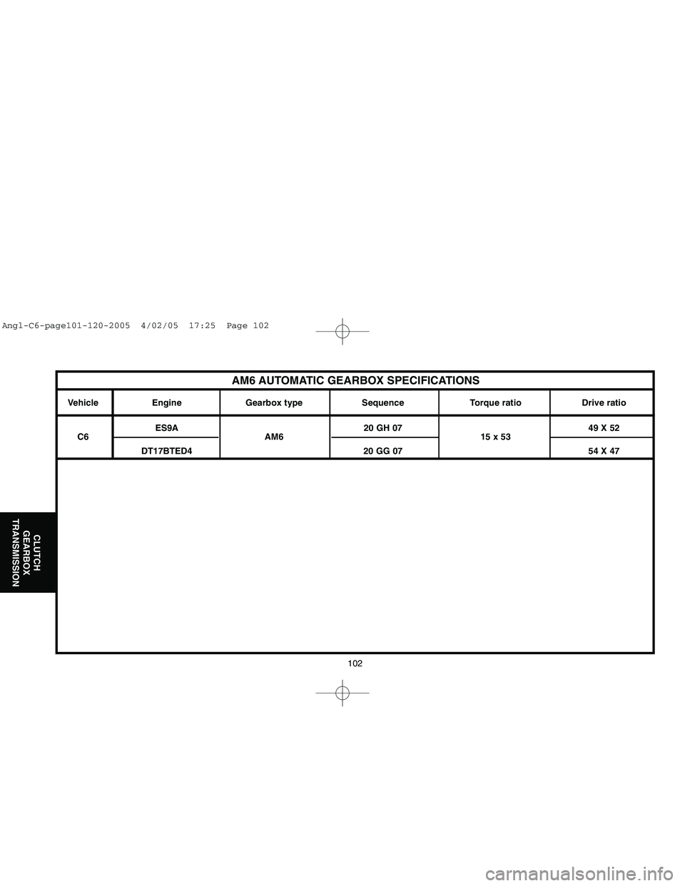
AM6 AUTOMATIC GEARBOX SPECIFICATIONS
Vehicle Engine Gearbox type Sequence Torque ratio Drive ratio
ES9A 20 GH 07 49 X 52
C6 AM6 15 x 53
DT17BTED4 20 GG 07 54 X 47
Angl-C6-page101-120-2005 4/02/05 17:25 Page 102
Page 109 of 223
Downloaded from www.Manualslib.com manuals search engine 103
CLUTCH
GEARBOX
TRANSMISSION
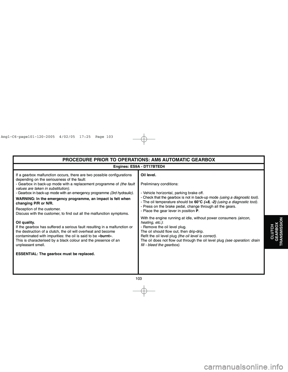
PROCEDURE PRIOR TO OPERATIONS: AM6 AUTOMATIC GEARBOX
If a gearbox malfunction occurs, there are two possible configurations
depending on the seriousness of the fault:
- Gearbox in back-up mode with a replacement programme of (the fault
values are taken in substitution).
- Gearbox in back-up mode with an emergency programme (3rd hydraulic).
WARNING: In the emergency programme, an impact is felt when
changing P/R or N/R.
Reception of the customer.
Discuss with the customer, to find out all the malfunction symptoms.
Oil quality.
If the gearbox has suffered a serious fault resulting in a malfunction or
the destruction of a clutch, the oil will overheat and become
contaminated with impurities: the oil is said to be «burnt».
This is characterised by a black colour and the presence of an
unpleasant smell.
ESSENTIAL: The gearbox must be replaced.Oil level.
Preliminary conditions:
- Vehicle horizontal, parking brake off.
- Check that the gearbox is not in back-up mode (using a diagnostic tool).
- The oil temperature should be 60°C (+8, -2)(using a diagnostic tool).
- Press on the brake pedal, change through all the gears.
- Place the gear lever in position P.
With the engine running at idle, without power consumers (aircon,
heating, etc.):
- Remove the oil level plug.
The oil should flow out, then drip-drip.
Refit the oil level plug (the oil level is correct).
The oil does not flow out through the oil level plug (see operation: drain
fill - bleed the gearbox).
Engines: ES9A - DT17BTED4
Angl-C6-page101-120-2005 4/02/05 17:25 Page 103
Page 110 of 223
Downloaded from www.Manualslib.com manuals search engine 104
CLUTCH
GEARBOX
TRANSMISSION
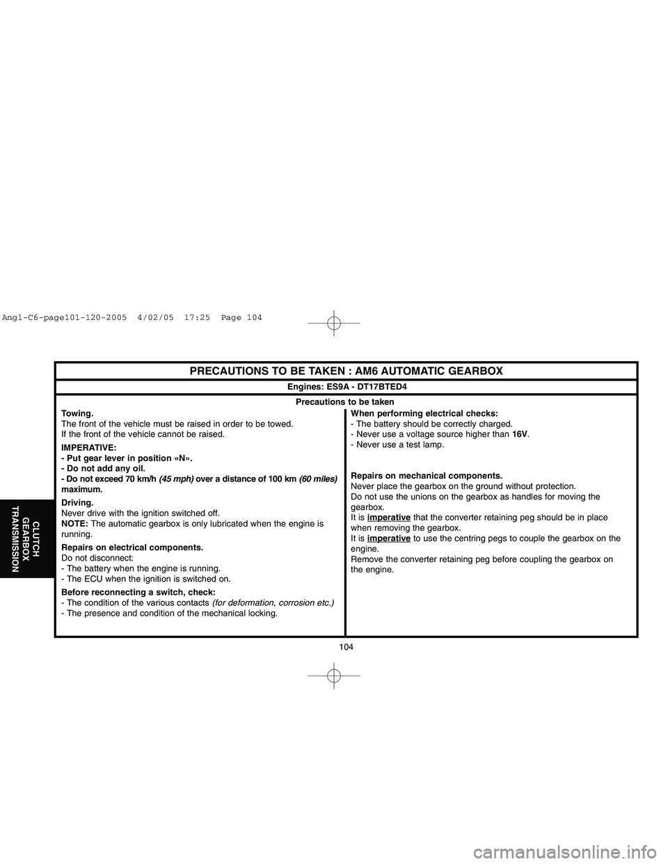
PRECAUTIONS TO BE TAKEN : AM6 AUTOMATIC GEARBOX
Towing.
The front of the vehicle must be raised in order to be towed.
If the front of the vehicle cannot be raised.
IMPERATIVE:
- Put gear lever in position «N».
- Do not add any oil.
- Do not exceed 70 km/h (45 mph)over a distance of 100 km (60 miles)
maximum.
Driving.
Never drive with the ignition switched off.
NOTE:The automatic gearbox is only lubricated when the engine is
running.
Repairs on electrical components.
Do not disconnect:
- The battery when the engine is running.
- The ECU when the ignition is switched on.
Before reconnecting a switch, check:
- The condition of the various contacts (for deformation, corrosion etc.)
- The presence and condition of the mechanical locking.When performing electrical checks:
- The battery should be correctly charged.
- Never use a voltage source higher than 16V.
- Never use a test lamp.
Repairs on mechanical components.
Never place the gearbox on the ground without protection.
Do not use the unions on the gearbox as handles for moving the
gearbox.
It is imperative
that the converter retaining peg should be in place
when removing the gearbox.
It is imperativeto use the centring pegs to couple the gearbox on the
engine.
Remove the converter retaining peg before coupling the gearbox on
the engine.
Engines: ES9A - DT17BTED4Precautions to be taken
Angl-C6-page101-120-2005 4/02/05 17:25 Page 104