CITROEN C6 2005 Manual Online
C6 2005
CITROEN
CITROEN
https://www.carmanualsonline.info/img/9/57744/w960_57744-0.png
CITROEN C6 2005 Manual Online
Trending: wheel torque, light, oil filter, brake, stop start, oil, recommended oil
Page 81 of 223
Downloaded from www.Manualslib.com manuals search engine 75
ENGINE
COOLING SYSTEM SPECIFICATIONS
Engine: DT17BTED4
(1)Header tank
(2)Coolant outlet housing
(3)Coolant/oil heat exchanger
(4)Coolant/EGR heat exchanger (rear cylinder bank)
(5)Bleed screw
(6)Heater matrix
(7)Additional heating unit
(8)Engine cooling radiator
(9)Engine cooling radiator drain tap
(10)Coolant/EGR heat exchanger (front cylinder bank)
B1GP0D4P
Angl-C6-page022-82-2005 4/02/05 17:19 Page 75
Page 82 of 223
Downloaded from www.Manualslib.com manuals search engine 76
ENGINE
CHECKING THE OIL PRESSURE
Engine ES9A DT17BTED4
Temperature (°C) 80°C
Pressure (bars) 2
Rpm 900
Pressure (bars) 5 1 to 4
Rpm 3000 2500
Pressure (bars)
Rpm
2279-T.BisX
4103-TX
(-).1503.KX
4202-T X
NOTE: Oil pressure should be checked with the engine cold, after checking the oil level.
Angl-C6-page022-82-2005 4/02/05 17:19 Page 76
Page 83 of 223
Downloaded from www.Manualslib.com manuals search engine 77
ENGINE
VALVE CLEARANCES
●Inlet
All types
Hydraulic adjustmentExhaust
Angl-C6-page022-82-2005 4/02/05 17:19 Page 77
Page 84 of 223
Downloaded from www.Manualslib.com manuals search engine 78
ENGINE
DRAINING, FILLING AND BLEEDING THE ENGINE COOLING CIRCUIT
Tools.
[1]Filling cylinder: 4520-T
[2]Adaptor for filling cylinder: 4222-T
[3]Control rod for filling cylinder: 4370-T
IMPERATIVE: Respect the safety and cleanliness requirements.
The draining and refilling operations can be carried out using coolant fluid replacement equipment.
It is essential to follow the instructions as stated for that equipment.
Draining.
Remove the header tank cap with caution (engine cold).
Open the bleed screw of the radiator.
Slacken the drain screw (1)of the radiator
Open the plug (2)to drain the first bank of cylinders.
NOTE:The plug (2)is provided with a drain tube.
B1GP0BPC
Engine: ES9A
B1BP2BNC
Angl-C6-page022-82-2005 4/02/05 17:19 Page 78
Page 85 of 223
Downloaded from www.Manualslib.com manuals search engine 79
ENGINE
DRAINING, FILLING AND BLEEDING THE ENGINE COOLING CIRCUIT
Open the plug (3)to drain the second bank of cylinders.
Remove the drain plugs (2)and (3).
Filling and bleeding the circuit.
Prior to any filling, rinse the cooling with fresh water.
WARNING: Check the sealing of the cooling circuit.
Open the bleed screws of the following components:
- Heater matrix outlet.
- Coolant outlet housing.
- Radiator.
Close the drain screw (1)of the radiator.
Refit the plugs (2)and (3)with a new seal ; tighten to3 ± 0,3 m.daN.
Fit the filling cylinder assembly [1], [3], and [2]on the filler aperture.
Fill the cooling circuit.
NOTE:Keep the filling cylinder full to the maximum.
B1GP08TC
Engine: ES9A
B1GP0BQC
Angl-C6-page022-82-2005 4/02/05 17:19 Page 79
Page 86 of 223
Downloaded from www.Manualslib.com manuals search engine 80
ENGINE
DRAINING, FILLING AND BLEEDING THE ENGINE COOLING CIRCUIT
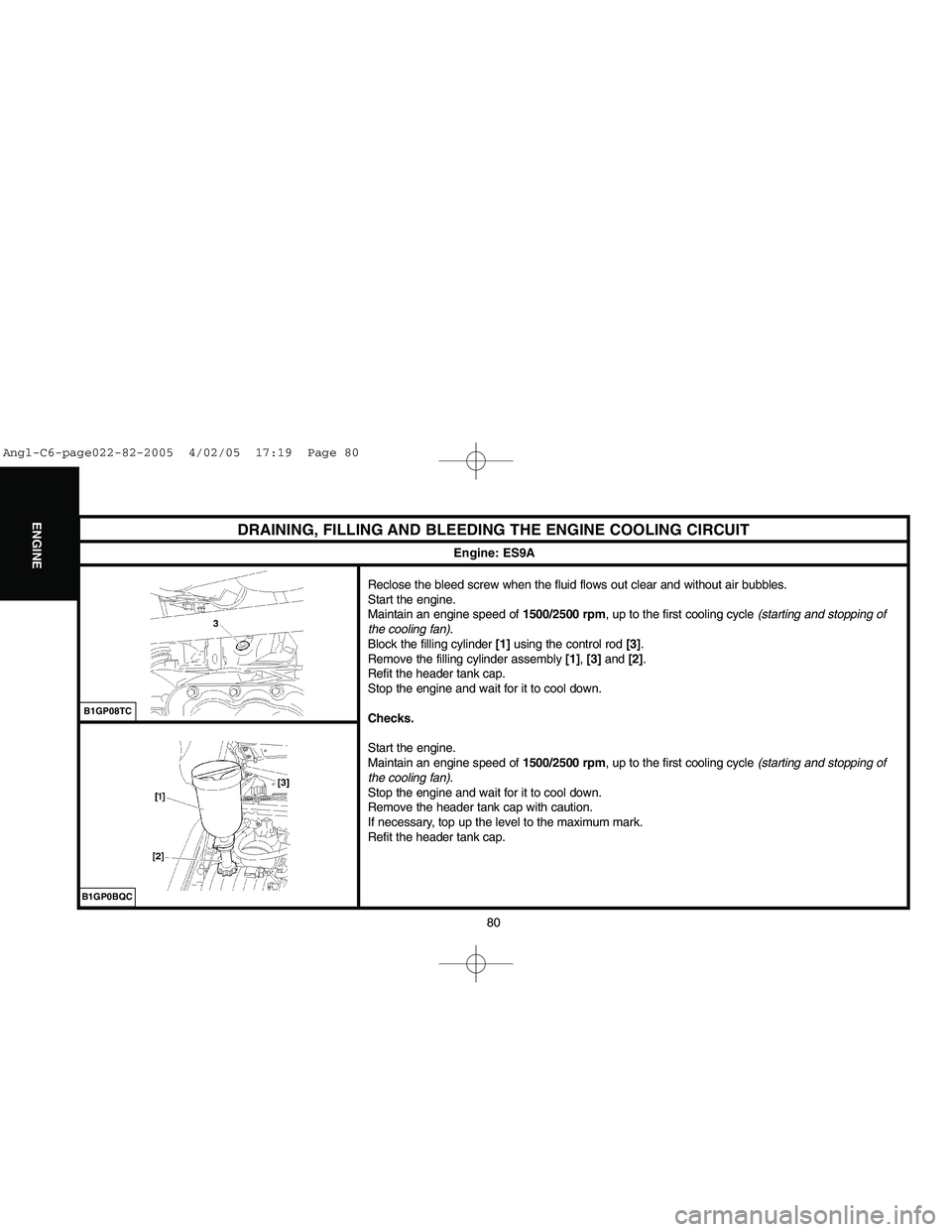
Reclose the bleed screw when the fluid flows out clear and without air bubbles.
Start the engine.
Maintain an engine speed of 1500/2500 rpm, up to the first cooling cycle (starting and stopping of
the cooling fan).
Block the filling cylinder [1]using the control rod [3].
Remove the filling cylinder assembly [1], [3]and [2].
Refit the header tank cap.
Stop the engine and wait for it to cool down.
Checks.
Start the engine.
Maintain an engine speed of 1500/2500 rpm, up to the first cooling cycle (starting and stopping of
the cooling fan).
Stop the engine and wait for it to cool down.
Remove the header tank cap with caution.
If necessary, top up the level to the maximum mark.
Refit the header tank cap.
B1GP08TC
Engine: ES9A
B1GP0BQC
Angl-C6-page022-82-2005 4/02/05 17:19 Page 80
Page 87 of 223
Downloaded from www.Manualslib.com manuals search engine 81
ENGINE
DRAINING, FILLING AND BLEEDING THE ENGINE COOLING CIRCUIT
Tools.
[1]Filling cylinder: 4520-T
[2]Adaptor for filling cylinder: 4222-T
[3]Control rod for filling cylinder: 4370-T
IMPERATIVE: Respect the safety and cleanliness requirements.
The draining and refilling operations can be carried out using coolant fluid replacement equipment.
It is essential to follow the instructions as stated for that equipment.
Draining.
Remove the header tank cap.
Open the bleed screw of the engine cooling radiator, located under the radiator on the LH side.
Remove the drain screw (1).
Drain the cylinder block.
Engine: DT17BTED4
B1GP0CNC
Angl-C6-page022-82-2005 4/02/05 17:19 Page 81
Page 88 of 223

Downloaded from www.Manualslib.com manuals search engine 82
ENGINE
DRAINING, FILLING AND BLEEDING THE ENGINE COOLING CIRCUIT
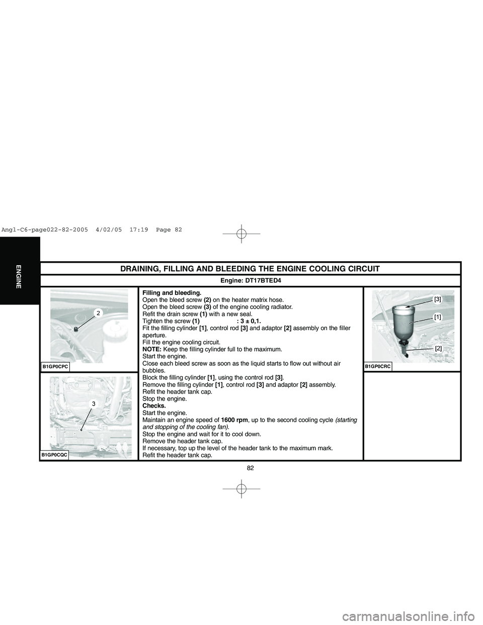
Filling and bleeding.
Open the bleed screw (2)on the heater matrix hose.
Open the bleed screw (3)of the engine cooling radiator.
Refit the drain screw (1)with a new seal.
Tighten the screw (1) : 3 ± 0,1.
Fit the filling cylinder [1], control rod [3]and adaptor [2]assembly on the filler
aperture.
Fill the engine cooling circuit.
NOTE:Keep the filling cylinder full to the maximum.
Start the engine.
Close each bleed screw as soon as the liquid starts to flow out without air
bubbles.
Block the filling cylinder [1], using the control rod [3].
Remove the filling cylinder [1], control rod [3]and adaptor [2] assembly.
Refit the header tank cap.
Stop the engine.
Checks.
Start the engine.
Maintain an engine speed of 1600 rpm, up to the second cooling cycle (starting
and stopping of the cooling fan).
Stop the engine and wait for it to cool down.
Remove the header tank cap.
If necessary, top up the level of the header tank to the maximum mark.
Refit the header tank cap.
Engine: DT17BTED4
B1GP0CQCB1GP0CPC
B1GP0CRC
Angl-C6-page022-82-2005 4/02/05 17:19 Page 82
Page 89 of 223
Downloaded from www.Manualslib.com manuals search engine 83
INJECTION
BOSCH ME 7.4.7 INJECTION SYSTEM
Engine: ES9A
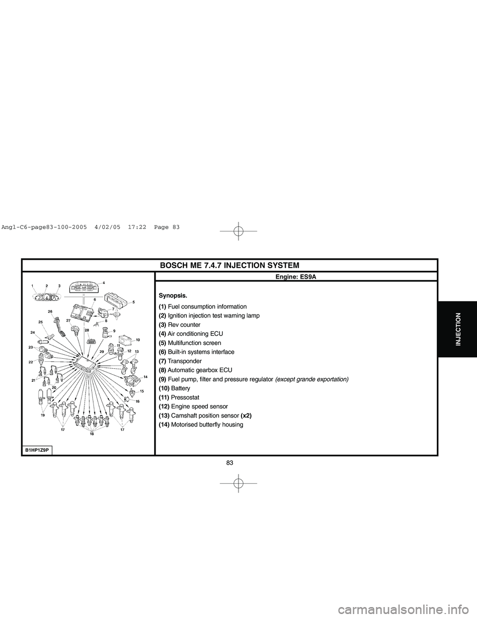
Synopsis.
(1) Fuel consumption information
(2)Ignition injection test warning lamp
(3)Rev counter
(4)Air conditioning ECU
(5)Multifunction screen
(6)Built-in systems interface
(7)Transponder
(8)Automatic gearbox ECU
(9)Fuel pump, filter and pressure regulator (except grande exportation)
(10)Battery
(11)Pressostat
(12)Engine speed sensor
(13)Camshaft position sensor (x2)
(14)Motorised butterfly housing
B1HP1Z9P
Angl-C6-page83-100-2005 4/02/05 17:22 Page 83
Page 90 of 223
Downloaded from www.Manualslib.com manuals search engine 84
INJECTION
BOSCH ME 7.4.7 INJECTION SYSTEM
Engine: ES9A
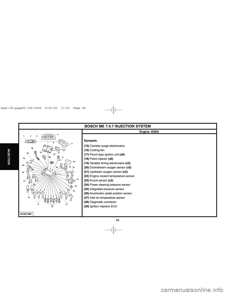
Synopsis.
(15) Canister purge electrovalve
(16)Cooling fan
(17)Pencil type ignition coil (x6)
(18)Petrol injector (x6)
(19)Variable timing electrovalve (x2)
(20)Downstream oxygen sensor (x2)
(21)Upstream oxygen sensor (x2)
(22)Engine coolant temperature sensor
(23)Knock sensor (x2)
(24) Power steering pressure sensor
(25)Integrated pressure sensor
(26)Accelerator pedal position sensor
(27)Inlet air temperature sensor
(28)Diagnostic connector
(29)Ignition injection ECU
B1HP1Z9P
Angl-C6-page83-100-2005 4/02/05 17:22 Page 84
Trending: engine oil capacity, tailgate, overheating, gas type, transmission oil, check engine, ABS


![CITROEN C6 2005 Manual Online Downloaded from www.Manualslib.com manuals search engine 78
ENGINE
DRAINING, FILLING AND BLEEDING THE ENGINE COOLING CIRCUIT
Tools.
[1]Filling cylinder: 4520-T
[2]Adaptor for filling cylinder: 4222-T CITROEN C6 2005 Manual Online Downloaded from www.Manualslib.com manuals search engine 78
ENGINE
DRAINING, FILLING AND BLEEDING THE ENGINE COOLING CIRCUIT
Tools.
[1]Filling cylinder: 4520-T
[2]Adaptor for filling cylinder: 4222-T](/img/9/57744/w960_57744-83.png)


![CITROEN C6 2005 Manual Online Downloaded from www.Manualslib.com manuals search engine 81
ENGINE
DRAINING, FILLING AND BLEEDING THE ENGINE COOLING CIRCUIT
Tools.
[1]Filling cylinder: 4520-T
[2]Adaptor for filling cylinder: 4222-T CITROEN C6 2005 Manual Online Downloaded from www.Manualslib.com manuals search engine 81
ENGINE
DRAINING, FILLING AND BLEEDING THE ENGINE COOLING CIRCUIT
Tools.
[1]Filling cylinder: 4520-T
[2]Adaptor for filling cylinder: 4222-T](/img/9/57744/w960_57744-86.png)


![CITROEN C6 2005 Manual Online Downloaded from www.Manualslib.com manuals search engine 78
ENGINE
DRAINING, FILLING AND BLEEDING THE ENGINE COOLING CIRCUIT
Tools.
[1]Filling cylinder: 4520-T
[2]Adaptor for filling cylinder: 4222-T CITROEN C6 2005 Manual Online Downloaded from www.Manualslib.com manuals search engine 78
ENGINE
DRAINING, FILLING AND BLEEDING THE ENGINE COOLING CIRCUIT
Tools.
[1]Filling cylinder: 4520-T
[2]Adaptor for filling cylinder: 4222-T](/img/9/57744/w960_57744-83.png)


![CITROEN C6 2005 Manual Online Downloaded from www.Manualslib.com manuals search engine 81
ENGINE
DRAINING, FILLING AND BLEEDING THE ENGINE COOLING CIRCUIT
Tools.
[1]Filling cylinder: 4520-T
[2]Adaptor for filling cylinder: 4222-T CITROEN C6 2005 Manual Online Downloaded from www.Manualslib.com manuals search engine 81
ENGINE
DRAINING, FILLING AND BLEEDING THE ENGINE COOLING CIRCUIT
Tools.
[1]Filling cylinder: 4520-T
[2]Adaptor for filling cylinder: 4222-T](/img/9/57744/w960_57744-86.png)


