Citroen GRAND C4 PICASSO RHD 2016 2.G Owner's Manual
Manufacturer: CITROEN, Model Year: 2016, Model line: GRAND C4 PICASSO RHD, Model: Citroen GRAND C4 PICASSO RHD 2016 2.GPages: 523, PDF Size: 13.63 MB
Page 291 of 523
289
Spare wheel
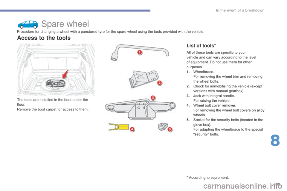
The tools are installed in the boot under the fl o o r.
Remove
the boot carpet for access to them.
Access to the tools
List of tools*
Procedure for changing a wheel with a punctured tyre for the spare wheel using the tools provided with the vehicle.
A ll of these tools are specific to your
vehicle
and can vary according to the level
o
f equipment. Do not use them for other
p
urposes.
1.
W
heelbrace.
F
or removing the wheel trim and removing
t
he wheel bolts.
2.
C
hock for immobilising the vehicle (except
v
ersions with manual gearbox).
3.
J
ack with integral handle.
F
or raising the vehicle.
4.
W
heel bolt cover remover.
F
or removing the wheel bolt covers on alloy
w
heels.
5.
S
ocket for the security bolts (located in the
g
love box).
F
or adapting the wheelbrace to the special
"s
ecurity"
b
olts.
*
According to equipment.
8
In the event of a breakdown
Page 292 of 523
290
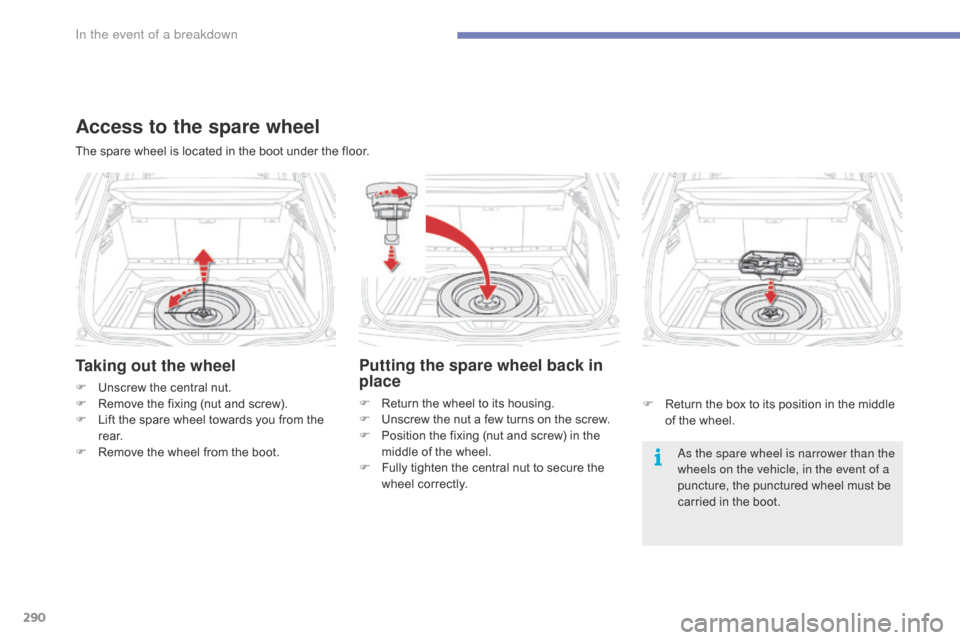
Taking out the wheel
F Unscrew the central nut.
F R emove the fixing (nut and screw).
F
L
ift the spare wheel towards you from the
r
e a r.
F
R
emove the wheel from the boot. As the spare wheel is narrower than the
wheels on the vehicle, in the event of a
puncture,
the punctured wheel must be
c
arried in the boot.
The
spare wheel is located in the boot under the floor.
Access to the spare wheel
Putting the spare wheel back in
place
F Return
the wheel to its housing.
F U nscrew the nut a few turns on the screw.
F
P
osition the fixing (nut and screw) in the
m
iddle of the wheel.
F
F
ully tighten the central nut to secure the
w
heel correctly. F
R eturn the box to its position in the middle
o
f the wheel.
In the event of a breakdown
Page 293 of 523
291
Spare wheelProcedure for changing a wheel with a punctured tyre for the spare wheel using the tools provided with the vehicle.
S
ome
of
the
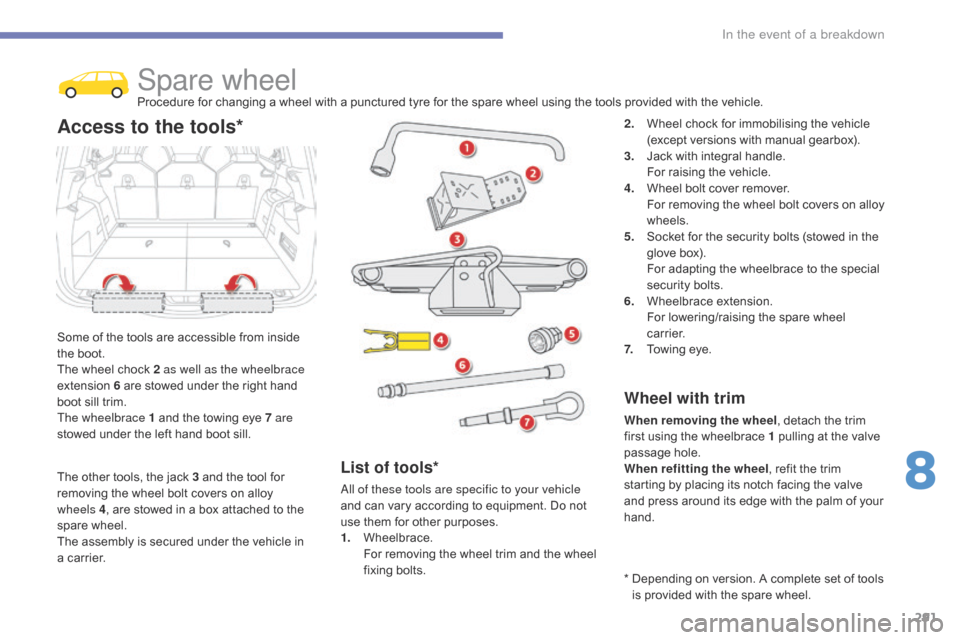
tools are accessible from inside
t
he
boot.
The
wheel
chock 2 as well as the wheelbrace
extension
6
are stowed under the right hand
b
oot
sill
trim.
The wheelbrace 1
and the towing eye 7 are
stowed
under
the left hand boot sill.
Access to the tools*2. Wheel chock for immobilising the vehicle (
except versions with manual gearbox).
3.
J
ack with integral handle.
F
or raising the vehicle.
4.
W
heel bolt cover remover.
F
or removing the wheel bolt covers on alloy
w
heels.
5.
S
ocket for the security bolts (stowed in the
g
love box).
F
or adapting the wheelbrace to the special
s
ecurity bolts.
6.
W
heelbrace
e
xtension.
F
or lowering/raising the spare wheel
c
a r r i e r.
7.
T
owing eye.
Wheel with trim
When removing the wheel , detach the trim f
irst using the wheelbrace 1 pulling at the valve
p
assage hole.
When refitting the wheel ,
refit the trim
s
tarting by placing its notch facing the valve
a
nd press around its edge with the palm of your
han
d.
List of tools*
All of these tools are specific to your vehicle
and can vary according to equipment. Do not
u
se them for other purposes.
1.
W
heelbrace.
F
or removing the wheel trim and the wheel
f
ixing
bol
ts. *
D
epending on version. A complete set of tools
i
s provided with the spare wheel.
The
other
tools,
the
jack
3
and
the
tool
for
r
emoving
the
wheel
bolt
covers
on
alloy
w
heels
4 ,
are
stowed
in
a
box
attached
to
the
spar
e
w
heel.
The
assembly
is
secured
under
the
vehicle
in
a
carrier.
8
In the event of a breakdown
Page 294 of 523
292
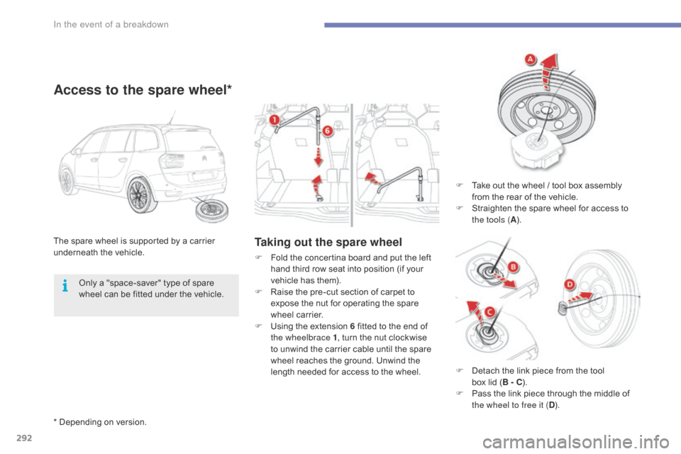
Taking out the spare wheelThe spare wheel is supported by a carrier underneath t he v ehicle.
Access to the spare wheel*
F Take out the wheel / tool box assembly f
rom the rear of the vehicle.
F
S
traighten the spare wheel for access to
t
he tools ( A).
F
F
old
the
concertina
board
and
put
the
left
h
and
third
row
seat
into
position
(if
your
v
ehicle
has
them).
F
R
aise
the
pre-cut
section
of
carpet
to
e
xpose
the
nut
for
operating
the
spare
w
heel
carrier.
F
U
sing
the
extension
6
fitted
to
the
end
of
t
he wheelbrace 1 ,
turn
the
nut
clockwise
t
o
unwind
the
carrier
cable
until
the
spare
w
heel
reaches
the
ground.
Unwind
the
l
ength
needed
for
access
to
the
wheel.
Only
a
"space-saver"
type
of
spare
w
heel
can
be
fitted
under
the
vehicle.
*
Depending
on
version. F
D
etach the link piece from the tool
b
ox lid ( B - C).
F
P
ass the link piece through the middle of
t
he wheel to free it ( D).
In the event of a breakdown
Page 295 of 523
293
A punctured wheel from the vehicle cannot be fitted under the vehicle. It
m
ust
b
e
c
arried
i
n
t
he
b
oot.
U
se
a
c
over
t
o protect the boot.
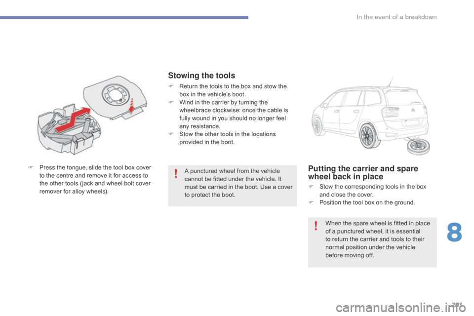
F
P
ress
the
tongue,
slide
the
tool
box
cover
t
o
the
centre
and
remove
it
for
access
to
t
he
other
tools
( jack
and
wheel
bolt
cover
r
emover
for
alloy
wheels).Putting the carrier and spare
wheel back in place
F Stow the corresponding tools in the box a
nd close the cover.
F
P
osition the tool box on the ground.
Stowing the tools
F Return the tools to the box and stow the b
ox in the vehicle's boot.
F
W
ind in the carrier by turning the
w
heelbrace clockwise: once the cable is
f
ully wound in you should no longer feel
an
y
r
esistance.
F
S
tow the other tools in the locations
provided
in the boot.
When
the spare wheel is fitted in place
o
f a punctured wheel, it is essential
t
o return the carrier and tools to their
n
ormal position under the vehicle
b
efore moving off.
8
In the event of a breakdown
Page 296 of 523
294
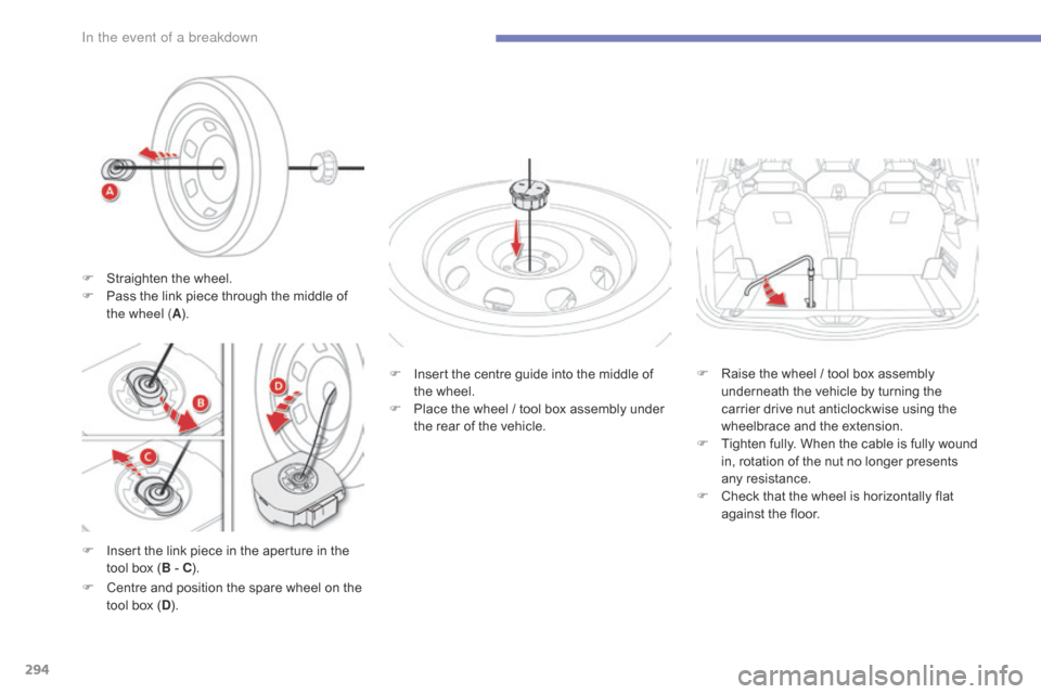
F Insert the link piece in the aperture in the t
ool box (B
- C). F
I
nsert the centre guide into the middle of
t
he wheel.
F
P
lace the wheel / tool box assembly under
t
he rear of the vehicle.
F
C
entre and position the spare wheel on the
t
ool box (D ). F
R
aise the wheel / tool box assembly
u
nderneath the vehicle by turning the
c
arrier drive nut anticlockwise using the
w
heelbrace and the extension.
F
T
ighten fully. When the cable is fully wound
i
n, rotation of the nut no longer presents
an
y
r
esistance.
F
C
heck that the wheel is horizontally flat
a
gainst the floor.
F
S
traighten the wheel.
F
P
ass the link piece through the middle of
t
he wheel (
A).
In the event of a breakdown
Page 297 of 523

295
Removing a wheel
Parking the vehicle
Immobilise the vehicle where it does not block traffic: the ground must be level,
s
table and not slippery.
Apply
the parking brake unless it has
b
een programmed to automatic mode,
s
witch off the ignition and engage first
g
ear* to block the wheels.
Check
that the braking warning lamp
a
nd the P warning lamp in the parking
b
rake control lever come on.
For
greater safety, place the chock 2
against
the wheel opposite to the one
b
eing
c
hanged.
The
occupants must get out of the
v
ehicle and wait where they are safe.
Never
go underneath a vehicle
s
upported by a jack; use an axle stand.
List of operations
F Remove the wheel bolt cover(s) using the t
ool 4 (depending on equipment).
F
F
it the security socket 5 on the
wheelbrace
1 to slacken the security bolt
(
if fitted).
F
S
lacken the other bolts (no more than a
1
/4 turn) using the wheelbrace 1
o
n l y.
* Position P
for
an
automatic
gearbox. Do
not use:
-
t
he jack for any purpose other than
l
ifting the vehicle,
-
a
ny other jack than the one
s
upplied by the manufacturer.F
P
lace the foot of the jack 3 on the ground
a
nd check that it is directly below the
f
ront A or rear B jacking point provided on
t
he underbody, whichever is closest to the w
heel to be changed.
Ensure that the jack is stable. If the
g
round is slippery or loose, the jack
m
ay slip or drop - Risk of injury!
Ensure
that the jack is positioned only
a
t one of the jacking points A or B
under
the vehicle, making sure that the
v
ehicle's contact sur face is centred on
t
he head of the jack. Other wise there is
a
risk of damage to the vehicle and/or of
t
he jack dropping - Risk of injury!
8
In the event of a breakdown
Page 298 of 523
296
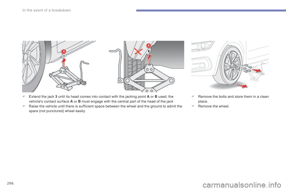
F Extend the jack 3 until its head comes into contact with the jacking point A or B used; the v
ehicle's contact sur face A or B must engage with the central part of the head of the jack
F
R
aise the vehicle until there is sufficient space between the wheel and the ground to admit the
s
pare (not punctured) wheel easily. F
R emove the bolts and store them in a clean p
lace.
F
R
emove the wheel.
In the event of a breakdown
Page 299 of 523
297
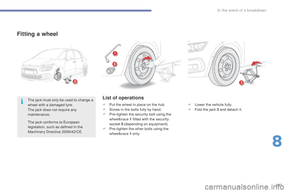
Fitting a wheel
F Lower the vehicle fully.
F F old the jack 3 and detach it.
List of operations
F Put the wheel in place on the hub.
F S crew in the bolts fully by hand.
F
P
re-tighten the security bolt using the
w
heelbrace 1 fitted with the security
s
ocket 5
(depending on equipment).
F
P
re-tighten the other bolts using the
w
heelbrace 1
o
n l y.
The
jack
must
only
be
used
to
change
a
w
heel
with
a
damaged
tyre.
The
jack
does
not
require
any
m
aintenance.
The
jack
conforms
to
European
l
egislation,
such
as
defined
in
the
M
achinery
Directive
2006/42/CE.
8
In the event of a breakdown
Page 300 of 523
298
Fitting the "space-saver"
spare wheel
If your vehicle is fitted with alloy wheels, when tightening the bolts on fitting, it
i
s normal to notice that the washers
d
o not come into contact with the
"
space-saver" spare wheel. The wheel
i
s secured by the conical sur face of
e
ach bolt.
After changing a wheel
To correctly store the punctured wheel in the boot ( not in the location for the
space-saver wheel ),
first remove the
c
entral cover.
When
using the "space-saver" type
s
pare wheel, do not exceed 50 mph
(
80 km/h).
Have
the tightening of the bolts and the
p
ressure of the spare wheel checked
b
y a CITROËN dealer or a qualified
w
orkshop without delay.
Have
the punctured wheel repaired
a
nd refitted to the vehicle as soon as
p
ossible.
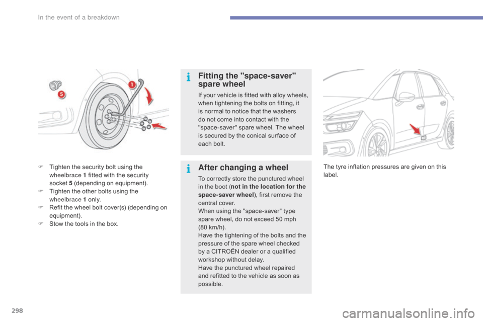
F
T
ighten
the
security
bolt
using
the
w
heelbrace 1
fitted
with
the
security
s
ocket 5
(depending
on
equipment).
F
T
ighten
the
other
bolts
using
the
w
heelbrace 1
o
n l y.
F
R
efit
the
wheel
bolt
cover(s)
(depending
on
e
quipment).
F
S
tow
the
tools
in
the
box. The
tyre inflation pressures are given on this lab
el.
In the event of a breakdown