lock DATSUN 210 1979 Service Manual
[x] Cancel search | Manufacturer: DATSUN, Model Year: 1979, Model line: 210, Model: DATSUN 210 1979Pages: 548, PDF Size: 28.66 MB
Page 368 of 548

1
Control
lever
2
Front
cable
3
Rear
cable
adjuster
4
Rear
cable
S
Strap
6
Oevis
1
Return
spring
REMOVAL
Removal
of
control
lever
and
front
ceble
Disconnect
terminal
from
hand
Brake
System
HAND
BRAKE
BA120A
Fig
BR
34
Hand
Broke
3
Remove
lock
plate
Disconnect
cable
adjuster
brake
warning
switch
2
Remove
bolts
securing
hand
brake
lever
to
floor
@
BR005A
Fig
BR
36
Removi1l
1
Front
Cable
1
Hand
brake
warning
switch
2
Terminal
3
Bolt
4
Pin
4
Pull
front
cable
out
into
driver
s
compartment
and
remove
it
together
with
control
assembly
5
If
necessary
separate
front
cable
from
hand
brake
lever
by
breaking
pin
and
replace
front
cable
B
R036A
CAUTION
Be
careful
not
to
deform
or
damage
control
lever
Fig
BR
35
Hand
Brake
Lever
BR
14
Page 369 of 548
Note
Front
cable
clevis
pin
and
cotter
pin
are
available
as
service
parts
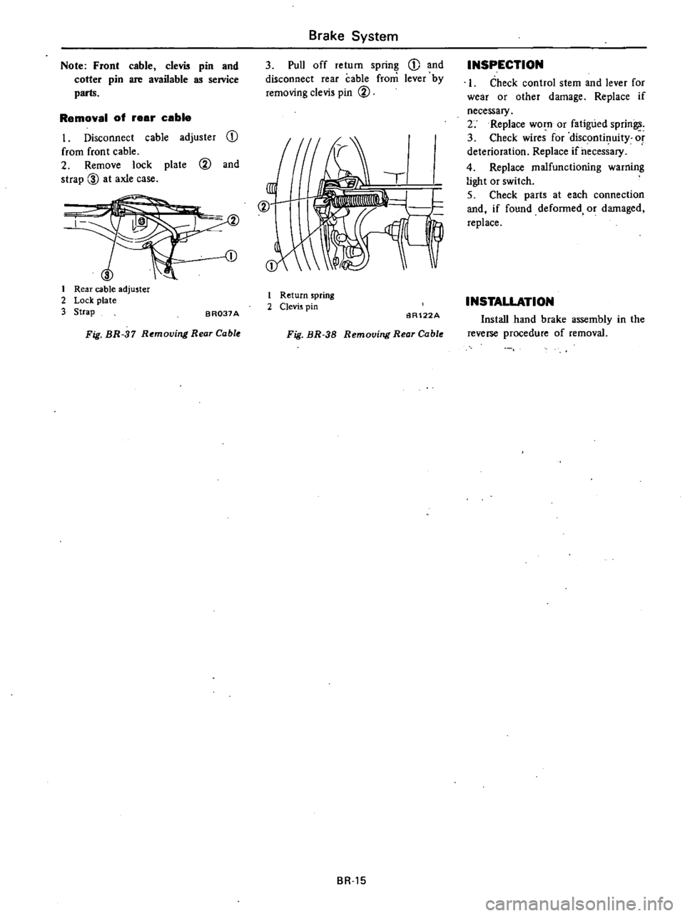
Removal
of
eer
ceble
I
Disconnect
cable
adjuster
CD
from
front
cable
2
Remove
lock
plate
@
and
strap
00
at
axle
case
1
I
Rear
cable
adjuster
2
Lock
plate
3
Strap
BR037A
Fig
BR
37
Removing
Rear
Cable
Brake
System
3
Pull
off
return
spring
CD
and
disconnect
rear
cable
from
lever
by
removing
clevis
pin
@
@
I
Return
spring
2
Clevis
pin
6R122A
Fig
BR
38
Removing
Rear
Cable
BR
15
INSPECTION
I
Check
control
stem
and
lever
for
wear
or
other
damage
Replace
if
necessary
2
Replace
worn
or
fatigued
sprin
3
Check
wires
for
discontinuity
or
deterioration
Replace
ifheces
ary
4
Replace
malfunctioning
warning
light
or
switch
5
Check
parts
at
each
connection
and
if
found
defonned
or
damaged
replace
INSTALLATION
Install
hand
brake
assembly
in
the
reverse
procedure
of
removal
Page 372 of 548
FRONT
DISC
BRAKE
Pad
wear
limit
Minim
urn
thickness
Rotor
repair
limit
Runout
Parallelism
Thickness
DRUM
BRAKE
Lining
wear
limit
Minimum
thickness
Drum
repair
limit
Maximum
inner
diameter
Initial
stage
203
2
nun
8
in
Out
of
roundness
Radial
cunout
Taper
Wheel
cylinder
repair
limit
Piston
to
cylinder
clearance
TIGHTENING
TORQUE
Master
cylinder
to
brake
booster
Brake
booster
to
body
Brake
tube
flare
nut
Brake
hose
connector
Air
bleeder
valve
3
way
connector
mounting
bolt
Brake
warning
lamp
switch
lock
nut
Caliper
fixing
bolt
Rotor
fixing
bolt
Rear
brake
wheel
cylinder
mounting
bolts
Front
brake
baffle
plate
fixing
bolts
Rear
brake
disc
fixing
bolts
BRAKE
BOOSTER
Brake
booster
to
body
Operating
rod
lock
nut
Flange
io
shell
cover
Push
rod
adjusting
nut
nun
in
nun
in
nun
in
mm
in
nun
in
nun
in
mm
in
nun
in
mm
in
nun
in
kg
m
ft
lb
kg
m
ft
lb
kg
m
ft
Ib
kg
m
ft
lb
kg
m
ft
Ib
kg
m
ft
lb
kg
m
ft
Ib
kg
m
ft
lb
kg
m
ft
Ib
kg
m
ft
lb
kg
m
ft
Ib
kg
m
ft
Ib
kg
m
ft
lb
kg
m
ft
lb
kg
m
ft
lb
kg
m
ft
lb
Brake
System
BR
1B
1
6
0
063
less
than
0
12
0
0047
less
than
0
03
0
0012
more
than
8
4
0
331
1
5
0
059
204
5
8
05
less
than
0
02
0
0008
less
than
0
1
0
004
less
than
0
02
0
0008
less
than
0
15
0
0059
0
8
to
1
1
5
8
to
8
0
0
8
to
1
1
5
8
to
8
0
1
5
to
1
8
II
to
13
1
7
to
2
0
12
to
14
0
7
to
0
9
5
1
to
6
5
0
8
to
1
1
5
8
to
8
0
l
2
to
1
5
9
to
II
7
3
to
9
9
53
to
72
3
9
to
5
3
28
to
38
0
6
to
0
8
4
3
to
5
8
0
34
to
0
44
2
5
to
3
2
2
2
to
2
7
16
to
20
0
8
to
1
1
5
8
to
8
0
1
6
to
2
2
12
to
16
0
8
to
1
1
5
8
to
8
0
1
6
to
2
2
12
to
16
Page 375 of 548
Condition
Brakes
drag
Brake
chatters
Brake
squeals
Pedal
pulsates
Rear
lock
under
light
brake
pedal
force
Rear
lock
under
heavy
brake
pedal
force
Brake
System
Probable
cause
Clogged
brake
lines
Incorrect
adjustment
of
wheel
bearings
Improper
shoe
to
drum
clearance
Weak
shoe
return
springs
No
free
travel
in
brake
shoe
return
Groove
or
out
of
round
brake
drum
or
rotor
Loose
or
bent
support
plate
Distorted
brake
shoes
or
pads
Grease
or
brake
fluid
on
linings
Dirty
or
scored
brake
drums
Distorted
brake
shoes
or
bent
support
plate
Weak
or
broken
brake
shoe
retaining
spring
or
return
spring
Glazed
or
contaminated
brake
lining
Out
of
round
or
off
center
drum
On
disc
brakes
lateral
runout
of
brake
rotor
is
excessive
Excessive
variation
in
thickness
of
brake
rotor
surfaces
Improper
tire
pressures
Excessive
wear
of
tires
Faulty
NP
valve
Improper
tire
pressures
Excessive
wear
of
tires
Poor
front
braking
effect
Grease
oil
mud
or
water
on
linings
or
pads
Excessive
wear
of
linings
or
pads
Local
fit
of
linings
or
pads
Master
cylinder
or
wheel
cylinder
in
poor
condition
BR
2t
Corrective
action
Check
and
clean
Adjust
or
repair
Adjust
Replace
Adjust
pedal
height
Grind
or
replace
as
required
Tighten
support
plate
bolts
to
specified
torque
or
replace
plate
Replace
as
necessary
Replace
linings
Blowout
assembly
with
compressed
air
or
refinish
drum
Replace
faulty
unit
Replace
if
faulty
Cam
ground
lining
to
elilninate
glaze
If
it
doesn
t
replace
linings
Turn
drum
or
replace
as
necessary
Check
with
dial
indicator
turning
disc
by
hand
If
runout
exceeds
specifications
re
place
disc
Measure
around
disc
face
with
micrometer
Replace
disc
as
required
Check
and
adjust
Check
and
replace
Replace
Check
and
adjust
Check
and
replace
Clean
or
replace
Replace
Shave
or
replace
Repair
or
replace
Page 384 of 548
DATSUN
210
Model
8310
Series
SECTIONST
STEERING
SYSTEM
CONTENTS
STEERING
COLUMN
AND
GEAR
STEERING
WHEEL
STEERING
LOCK
STEERING
COLUMN
Collapsible
type
STEERING
GEAR
RB45L
STEERING
LINKAGE
SERVICE
DATA
AND
SPECIFICATIONS
ST
2
ST
2
ST
3
ST
3
ST
5
ST
9
GENERAL
SPECIFICATIONS
INSPECTION
AND
ADJUSTMENT
TIGHTENING
TORQUE
TROUBLE
DIAGNOSES
AND
CORRECTIONS
SPECIAL
SERVICE
TOOLS
ST
12
ST
12
ST
13
ST
14
ST
15
ST
12
Page 385 of 548
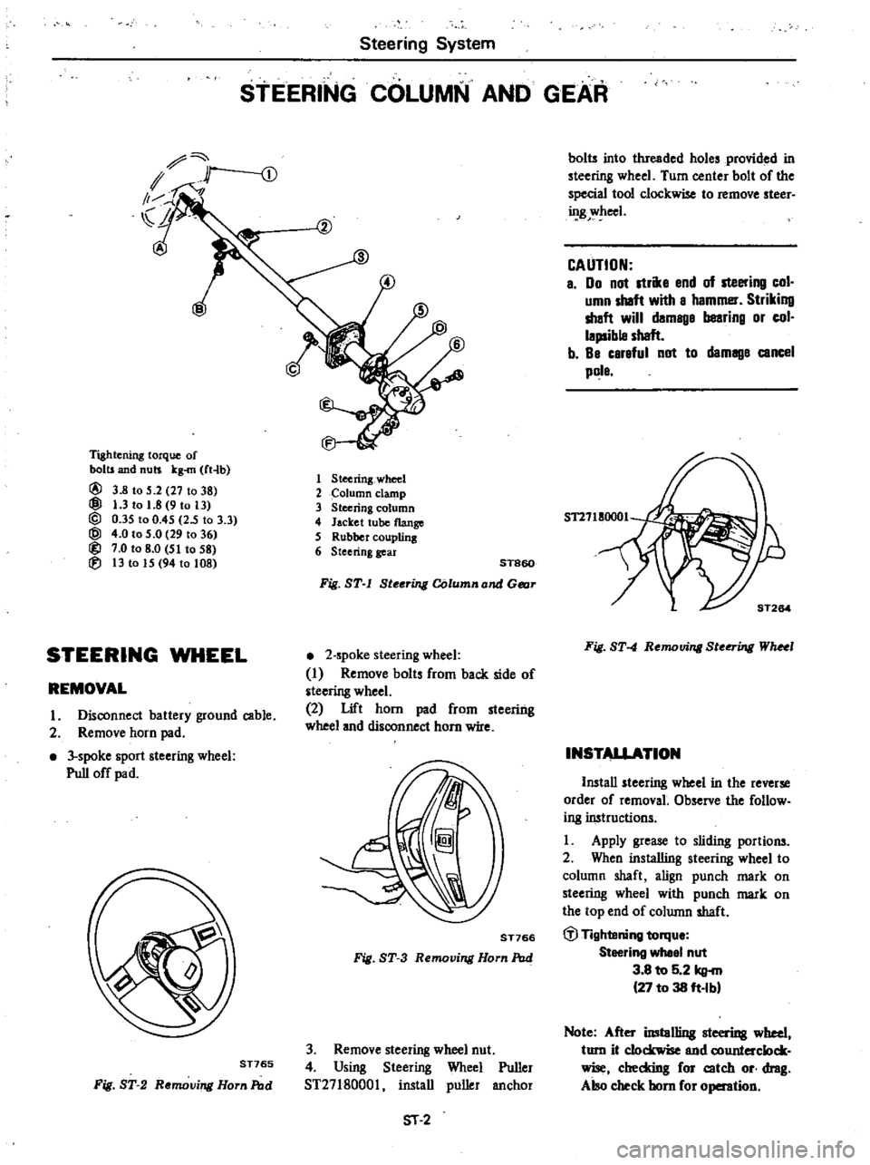
Steering
System
STEERING
COLUMN
AND
GEAR
Tightening
torque
of
bolts
and
nuts
kg
rn
ft4b
@
3
8
to
5
2
27
to
38
@
1
3
to
1
8
9
to
13
@
0
35
to
0
45
25
to
3
3
@
4
0
to
5
0
29
to
36
@
7
0
to
8
0
51
to
58
lEi
13
to
15
94
to
108
1
Steering
wheel
2
olumn
clamp
3
Steering
column
4
Jacket
tube
flange
S
RUbbercoupling
6
Steering
gear
ST860
Fig
ST
l
Steering
Column
and
Gear
STEERING
WHEEL
2
spoke
steering
wheel
I
Remove
bolts
from
back
side
of
steering
wheel
2
Lift
horn
pad
from
steering
wheel
and
disconnect
horn
wire
REMOVAL
I
Disconnect
battery
ground
cable
2
Remove
horn
pad
3
spoke
sport
steering
wheel
Pull
off
pad
ST766
Fig
ST
3
Removing
Horn
Pod
ST765
Fig
ST
2
Removing
Horn
Pod
3
Remove
steering
wheel
nut
4
Using
Steering
Wheel
Puller
ST2718000l
install
puller
anchor
51
2
bolts
into
threaded
holes
provided
in
steering
wheel
Turn
center
bolt
of
the
special
tool
clockwise
to
remove
steer
ing
wheel
CAUTION
a
00
not
strike
end
of
steering
col
umn
shaft
with
a
hammer
Striking
shaft
will
damage
bearing
or
col
lapsible
shaft
b
Be
careful
not
to
damage
cancel
pole
Fig
ST
4
Removing
Ste
ing
WhHl
INSTALLATION
Install
steering
wheel
in
the
reverse
order
of
removal
Observe
the
follow
ing
instructions
Apply
grease
to
sliding
portions
2
When
installing
steering
wheel
to
column
shaft
align
punch
mark
on
steering
wheel
with
punch
mark
on
the
top
end
of
column
shaft
til
Tightening
torqu
Steering
whee
nut
3
8
to
5
2
kg
27
to
38
ft
Ibl
Note
After
imtol1ing
steering
wheel
turn
it
clockwise
end
counterclock
wise
cheddng
for
catch
or
drag
Also
check
horn
for
operation
Page 386 of 548
STEERING
LOCK
To
provide
tamper
proof
self
shear
type
screws
are
used
and
their
heads
are
sheared
off
when
installed
so
that
the
steering
lock
system
cannot
be
removed
easily
REMOVAL
I
Break
two
self
shear
type
screws
with
a
drill
or
other
proper
tool
Steering
System
2
Remove
two
screws
and
dismount
steering
lock
from
steering
jacket
tube
ST393
Fig
ST
5
Removing
Steering
Lock
Securing
Screw
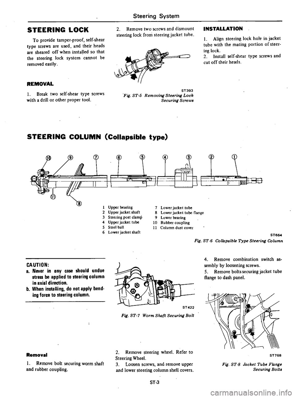
STEERING
COLUMN
Collapsible
type
1
H
f
II
CAUTION
a
Never
in
any
case
should
undue
strass
be
applied
to
steering
column
in
axial
direction
b
Whan
installing
do
not
apply
bend
ing
force
to
steering
column
Removel
I
Remove
bolt
securing
worm
shaft
and
rubber
coupling
INSTALLATION
I
Align
steering
lock
hole
in
jacket
tube
with
the
mating
portion
of
steer
ing
lock
2
Install
self
shear
type
screws
and
cut
off
their
heads
i
4
T
C
F
Lu
J
r
1
V
F
1
Upper
bearing
2
Upper
jacket
shaft
3
Steering
post
clamp
4
Upper
jacket
tube
5
Steel
ball
6
Lower
jacket
shaft
7
Lower
jacket
tube
8
Lower
jacket
tube
flange
9
Lower
bearing
10
Rubber
coupling
11
Column
dust
cover
it
j
a
ST
422
Fig
ST
7
Worm
8lwft
Securing
Bolt
2
Remove
steering
wheel
Refer
to
Steering
Wheel
3
Loosen
screws
and
remove
upper
and
lower
steering
column
shell
covers
ST
3
ST664
Fig
8T
6
Collapsibte
Type
Steoring
Column
4
Remove
combination
switch
as
sembly
by
loosening
screws
5
Remove
baIts
securing
jacket
tube
flange
to
dash
panel
ST768
Fig
8T
8
Jacket
Tube
Flange
Securing
Bolt
Page 388 of 548
Inspection
I
When
steering
wheel
can
not
be
rotated
smoothly
but
steering
gear
steering
linkage
and
suspension
system
are
normal
check
the
steering
system
for
the
following
matters
and
replace
faulty
parts
I
Check
column
bearings
for
dam
age
or
unevenness
If
so
lubricate
with
recommended
multi
purpose
grease
or
replace
with
a
new
one
as
steering
column
assembly
2
Check
jacket
tube
for
deforma
tion
or
breakage
and
replace
if
neces
sary
3
Check
column
spring
and
re
place
if
damaged
or
weakened
2
When
the
car
comes
into
light
collision
check
the
following
parts
and
replace
if
necessary
I
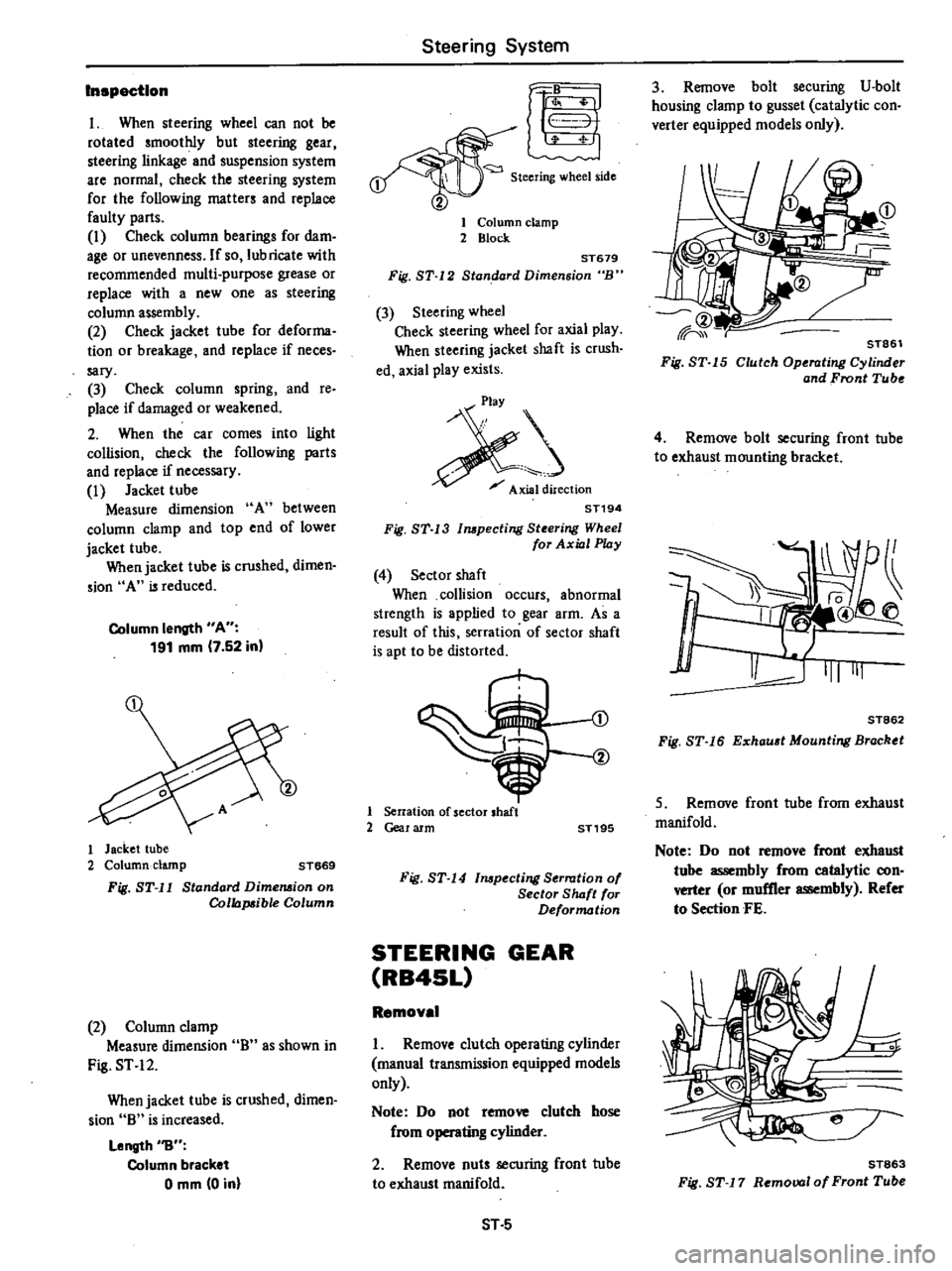
Jacket
tube
Measure
dimension
A
between
column
clamp
and
top
end
of
lower
jacket
tube
When
jacket
tube
is
crushed
dimen
sion
A
is
reduced
Column
length
A
191
mm
7
52
in
1
Jacket
tube
2
Column
clamp
ST669
Fig
ST
l1
Standard
Dimension
on
Collapsible
Column
2
Column
clamp
Measure
dimension
0
as
shown
in
Fig
ST
12
When
jacket
tube
is
crushed
dimen
sion
0
is
increased
Length
1J
Column
bracket
o
mm
0
in
Steering
System
r
1
Steering
wheel
side
1
Column
clamp
2
Block
ST679
Fig
ST
12
Standard
Dimension
B
3
Steering
wheel
Check
steering
wheel
for
axial
play
When
steering
jacket
shaft
is
crush
ed
axial
play
exists
j
Axial
direction
ST194
Fig
ST
13
mpecting
Steering
Wheel
for
Axial
Play
4
Sector
shaft
When
collision
occurs
abnormal
strength
is
applied
to
gear
arm
As
a
result
of
this
serration
of
sector
shaft
is
apt
to
be
distorted
1
Serration
of
sector
shaft
2
Gear
arm
ST195
Fig
ST
14
mpeeting
Serration
of
Sector
S
IuJft
for
Deformation
STEERING
GEAR
RB4SL
Removal
I
Remove
clutch
operating
cylinder
manual
transmission
equipped
models
only
Note
Do
not
remove
clutch
hose
from
8
cylinder
2
Remove
nuts
securing
front
tube
to
exhaust
manifold
ST
5
3
Remove
bolt
securing
V
bolt
housing
clamp
to
gusset
catalytic
con
verter
equipped
models
only
STa6l
Fig
ST
5
Clutch
Operating
Cylinder
and
Front
Tube
4
Remove
bolt
securing
front
tube
to
exhaust
mounting
bracket
1
Q
I
II
@
J
111111
ST862
Fig
ST
16
Exhau
t
Mounting
Bracktt
5
Remove
front
tube
from
exhaust
manifold
Note
Do
not
remove
front
exhaust
tube
assembly
from
catalytic
con
verter
or
muffler
assembly
Refer
to
Section
FE
ST863
Fig
ST
7
Removal
of
Front
Tube
Page 389 of 548
Steering
System
6
Reriiovebolt
Securing
worm
shaft
to
rubber
coupling
7
Remove
nut
and
lock
washer
se
curing
gear
arm
to
sector
shaft
Using
Steering
Gear
Arm
Puller
512902000
I
remove
steering
gear
arm
from
sector
shaft
Gear
housinif
I
0
Cearar
8
Remove
bolts
securing
steering
gear
housing
to
body
side
member
and
withdraw
steering
gear
housing
from
engine
compartment
n
ST289
Fig
ST
IB
Removing
Ste
i1l
Gear
Arm
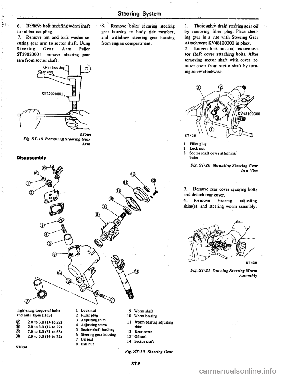
Disassembly
f
Tightening
torque
of
bolts
and
nuts
kg
m
ft
Ib
@
2
0
to
3
0
14
to
22
@
2
0
to
3
0
14
to
22
@
7
0
to
8
0
51
to
58
@
2
0
to
3
0
14
to
22
ST864
1
Lock
nut
2
Filler
plug
3
Adjusting
shim
4
Adjusting
screw
5
Sector
shaft
bushing
6
Steering
gearhou
ing
7
Oil
seal
8
BaU
nut
9
Worm
shaft
10
Wonn
bearing
11
Wann
bearing
adjUsting
shim
12
Rear
cover
13
Oil
seal
14
Sector
shaft
Fig
ST
19
Steeri1l
Gear
SHi
Thoroughly
drail
steCring
gear
oil
by
removing
filler
plug
Place
steer
ing
gear
in
a
vise
with
Steering
Gear
Attachment
KV48100300
in
place
2
Loosen
lock
nut
and
remove
see
tor
shaft
cover
attaching
bolts
After
removing
sector
shaft
with
cover
re
move
cover
from
sector
shaft
by
turn
ing
screw
clockwise
1
Filler
plug
2
Lock
nut
3
Sector
shaft
cover
attaching
bolts
Fig
ST
20
Mounti1l
Steeri1l
Gear
in
a
Vue
3
Remove
rear
cover
securing
bolts
and
detach
rear
cover
4
Remove
bearing
adjusting
shim
s
and
steering
worm
assembly
ST
426
Fig
ST
21
Drawi1l
Steeri1l
Worm
A
em
b
y
Page 391 of 548
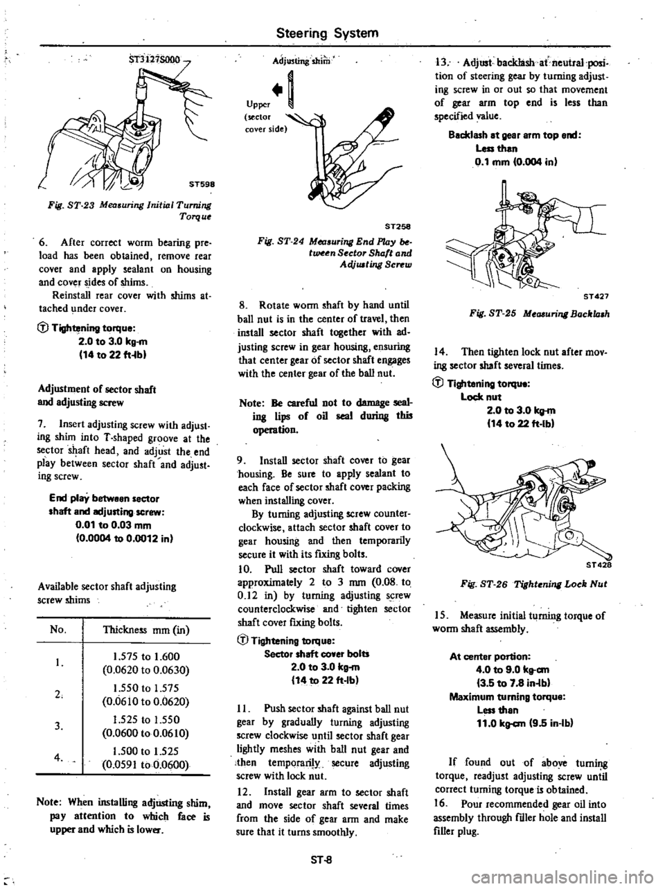
Fig
ST
23
Mea
uring
Initial
Turning
Torque
6
After
correct
worm
bearing
pre
load
has
been
obtained
remove
rear
cover
and
apply
sealant
on
housing
and
cover
sides
of
shims
Reinstall
rear
cover
with
shims
at
tached
under
cover
fJ
Tightening
torque
2
0
to
3
0
kg
m
14
to
22
fHbl
Adjustment
of
sector
shaft
and
adjusting
screw
7
Insert
adjusting
screw
with
adjust
ing
shUn
into
T
shaped
groove
at
the
sector
aft
head
and
adjust
the
end
play
between
sector
shaft
and
adjust
ing
screw
End
play
betwean
sector
shaft
and
IKljusting
screw
0
01
to
0
03
mm
0
0004
to
0
0012
in
Available
sector
shaft
adjusting
screw
shims
No
Thickness
mm
in
2
1
575
to
1
600
0
0620
to
0
0630
1
550
to
1
575
0
0610
to
0
0620
1
525
to
1
550
0
0600
to
0
0610
1
500
to
1
525
0
0591
to
0
0600
3
4
Note
When
installing
adjUsting
shim
pay
attention
to
which
face
is
upper
and
which
is
lower
Steering
System
Adjusting
shilli
Upper
1
sector
l
cover
side
ST258
Fig
ST
24
Measuri
End
l
UJy
tween
Sector
Shaft
and
AeVusting
Screw
8
Rotate
wonn
shaft
by
hand
until
ball
nut
is
in
the
center
of
travel
then
install
sector
shaft
together
with
ad
justing
screw
in
gear
housing
ensuring
that
center
gear
of
sector
shaft
engages
with
the
center
gear
of
the
ball
nut
Note
Be
careful
not
to
damage
seal
ing
lips
of
oil
seal
during
thi5
operation
9
Install
sector
shaft
cover
to
gear
chousing
Be
sure
to
apply
sealant
to
each
face
of
sector
shaft
cover
packing
when
installing
cover
By
turning
adjusting
screw
counter
clockwise
attach
sector
shaft
cover
to
gear
housing
and
then
temporarily
secure
it
with
its
futing
bolts
10
Pull
sector
shaft
toward
cover
approxUnately
2
to
3
mm
0
08
to
0
12
in
by
turning
adjusting
screw
counterclockwise
and
tighten
sector
shaft
cover
fIXing
bolts
fJ
Tightening
torque
Sector
shaft
co
er
bolts
2
0
to
3
0
kg
m
14
to
22
ft
Ib
II
Push
sector
shaft
against
ball
nut
gear
by
gradually
turning
adjusting
screw
clockwise
until
sector
shaft
gear
lightly
meshes
with
ball
nut
gear
and
then
temporarily
secure
adjusting
screw
with
lock
nut
12
Install
gear
arm
to
sector
shaft
and
move
sector
shaft
several
times
from
the
side
of
gear
ann
and
make
sure
that
it
turns
smoothly
SHl
13
Adjust
backIashat
neutral
posic
tion
of
steering
gear
by
turning
adjust
iog
screw
in
or
out
so
that
movement
of
gear
arm
top
end
is
less
than
specified
value
Backlash
at
gear
arm
top
end
Less
than
0
1
mm
0
004
in
ST
427
Fig
ST
25
Measuri
Bocklash
14
Then
tighten
lock
nut
after
mov
ing
sector
shaft
several
tUnes
fJ
Tightening
torqu
Lock
nut
2
0
to
3
0
kg
m
14
to
22
ft
Ibl
ST
428
Fig
ST
26
Tighteni
Loek
Nut
15
Measure
initial
turning
torque
of
wonn
shaft
assembly
At
center
portion
4
0
to
9
0
kt
c
m
3
5
to
7
8
in
lbl
Maximum
turning
torque
Less
than
11
0
kg
c
m
9
5
in
Ib
If
found
out
of
above
turning
torque
readjust
adjusting
screw
uniil
correct
turning
torque
is
obtained
16
Pour
recommended
gear
oil
into
assembly
through
fdler
hole
and
install
filler
plug