lock DATSUN 210 1979 Manual Online
[x] Cancel search | Manufacturer: DATSUN, Model Year: 1979, Model line: 210, Model: DATSUN 210 1979Pages: 548, PDF Size: 28.66 MB
Page 276 of 548

X
F
1
2
dll
U
Sflift
lllvI
21
I
S
nd
lock
6
Ir
II
P
UX
6
I
Mo
ol
f
L
t
u
uu
u
u
I
f5
LI
P
OI
I
Go
o
fo
d
P
I
ren
e
2nd
eer
Torqul
con
rter
Oil
pump
Oil
tool
RIAr
Ivbri
cor
ion
D
Orain
fa
hi
Front
lubrici
lti
0
0
0
1
I
tU
x
j
Pr
l
UQU
010r
Yol
u
1
Automatic
Transmission
Front
lulch
Riot
x
l
N
r
N
N
I
I
i
l
I
18
16
ahl
J
@
Vacuum
Huottl
Vol
if
J
II
Throttl
drain
yol
l
II
@2ft
3rd
Shiff
101
1
iii
1J
g
2nd
3rd
timino
101
11
8
Goy
rnor
prlUUAI
Torque
Cony
tar
pr
r
Th
toni
pt
ure
Slcondor
governor
vol
1
Primo
00
vlrnor
va
AT461
Fig
AT
21
Oil
Pr
Circuit
Dwgrom
12
ro
2nd
ear
AT
24
Page 277 of 548
Automatic
Transmission
REMOVAL
AND
INSTALLATION
TRANSMISSION
ASSEMBLY
When
dismounting
the
automatic
transmission
from
a
car
pay
attention
to
the
following
points
I
Before
dismounting
the
trans
mission
rigidly
inspect
it
by
aid
of
the
Trouble
shooting
Chart
and
dis
mount
it
only
when
coll5idered
to
be
necessary
2
Dismount
the
transmission
with
utmost
care
and
when
mounting
observe
the
tightening
torque
indi
cated
on
another
table
not
to
exert
excessive
force
REMOVAL
In
dismounting
automatic
transmis
sion
from
car
proceed
as
follows
I
Disconnect
battery
ground
cable
from
terminal
2
Disengage
torsion
shaft
from
ac
eelerator
linkage
3
Jack
up
vehicle
and
support
its
weight
on
safety
stands
Recommend
a
hydraulic
hoist
or
open
pit
be
utilized
if
available
Make
sure
that
safety
is
insured
4
Remove
propeller
shaft
Note
Pl
ll
up
the
openina
in
the
rear
extension
to
prevent
oil
from
flow
ing
out
S
Disconnect
front
exhaust
tube
6
Disconnect
selector
ra
8e
lever
from
manual
shaft
7
Disconnect
wire
connections
at
inhibitor
switch
8
Disconnect
vacuum
lube
from
vacuum
diaphragm
and
wire
connee
tions
at
downshift
solenoid
9
Disconnect
speedometer
cable
from
rear
exlension
10
Disconnect
oil
charging
pipe
II
Disconnect
oil
cooler
inlet
and
outlet
tubes
al
transmission
case
12
Support
engine
by
locating
a
jack
under
oil
pan
with
a
wooden
block
used
between
oil
pan
and
jack
Support
transmission
by
means
of
a
transmission
jack
CAUTION
Do
not
plecs
the
jack
under
the
oil
pin
dnin
plug
13
Detach
converter
housing
dust
cover
Remove
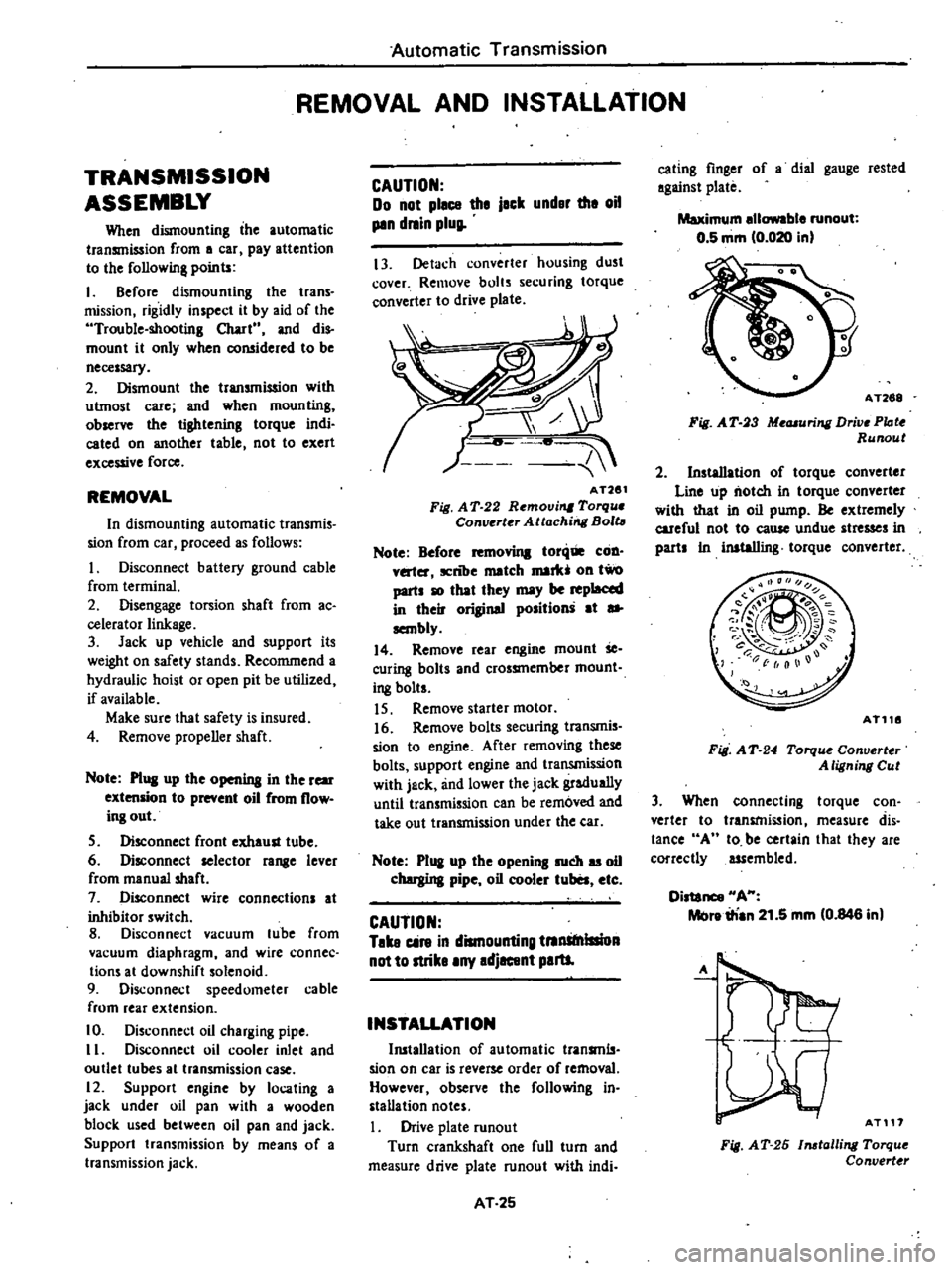
bolts
securing
torque
converter
to
drive
plate
AT261
Fig
A
T
22
Removi
Torqu
Converter
Attachirrg
Bolt
Note
Before
toni
COD
v
ter
ICnlJe
match
mark
011
two
parts
10
that
they
may
be
replaced
in
their
original
position
at
sa
sembly
14
Remove
rear
engine
mount
Se
curing
bolts
and
crossmember
mount
i
8
bolts
IS
Remove
starter
motor
16
Remove
bolts
securing
transmis
sion
to
engine
After
removing
these
bolts
support
engine
and
transmission
with
jack
and
lower
the
jack
gradually
until
transmission
can
be
removed
and
take
out
transmission
under
the
ear
Note
P1
I
up
the
opening
such
u
oil
chergina
pipe
oil
cooler
tuba
etc
CAUTION
Take
cin
in
dismounting
tnnStnlllioA
not
to
strike
any
adjacent
paru
INSTALLATION
Ill5tallation
of
automatic
transmls
sian
on
car
is
reverse
order
of
removal
However
observe
the
following
in
stallation
notes
Drive
plate
runout
Turn
crankshaft
one
full
turn
and
measure
drive
plate
runout
with
indi
AT
25
eating
finger
of
a
dial
gauge
rested
against
plate
Maximum
ellowable
runout
0
5
mm
0
020
in
AT268
Fig
A
T
3
Me
uring
Drive
PIote
Runout
2
Installation
of
torque
converter
Line
up
notch
in
torque
converter
with
that
in
oil
pump
Be
extremely
careful
not
to
eause
undue
stresses
in
parts
In
inataIIing
torque
converter
AT116
Fig
A
T
24
Torqu
Converter
A
ligning
Cut
3
When
connecting
torque
con
verter
to
transmission
measure
dis
tance
A
10
be
certain
that
they
are
correctly
assembled
Distance
HA
Melre
irian
21
5
mm
0
846
in
A
AT117
Fig
AT
26
1116talling
Torque
Convert
r
Page 279 of 548

Automatic
Transmission
MAJOR
REPAIR
OPERATION
SERVICE
NOTICE
FOR
DISASSEMBLY
AND
ASSEMBLY
I
It
is
advisable
that
repair
opera
tions
be
carried
out
in
a
dust
proof
room
2
Due
to
the
differences
of
the
engine
capacities
the
specifications
of
component
parts
for
each
model
s
transmission
may
be
different
They
do
however
have
common
adjust
ment
and
repair
procedures
as
well
as
cleaning
and
inspection
procedures
outlined
hereinafter
3
During
repair
operations
refer
to
Service
Data
and
Specific3ti
H1s
see
tion
for
the
correct
parts
for
each
model
4
Before
removing
any
of
subas
semblies
thoroughly
clean
the
outside
of
the
transmission
to
prevent
dirt
from
entering
the
mechanical
parts
5
Do
not
use
a
waste
rag
Use
a
nylon
or
paper
cloth
6
After
disassembling
wash
all
dis
assembled
parts
and
examine
them
to
see
if
there
3re
any
worn
damaged
or
defective
parts
and
how
they
are
affected
Refer
to
Service
Data
for
the
extent
of
damage
that
justifies
replacement
7
As
a
rule
packings
seals
and
similar
parts
once
disassembled
should
be
replaced
with
new
ones
TORQUE
CONVERTER
The
torque
converter
is
a
welded
construction
and
can
not
be
disas
sembled
INSPECTION
I
Check
torque
convert
for
any
sign
of
damage
bending
oil
leak
or
deformation
If
necessary
replace
2
Remove
rust
from
pilots
and
bosses
completely
If
torque
converter
oil
is
fouled
or
contaminated
due
to
burnt
clutch
flush
the
torque
converter
as
follows
I
Drain
oil
in
torque
converter
2
Pour
non
lead
gasoline
or
kero
sene
into
torque
converter
approxi
mately
0
5
liter
I
J
V
S
pt
U
Imp
pt
3
Blow
air
into
torque
converter
and
flush
and
drain
out
gasoline
4
Fill
torque
converter
with
torque
converter
oil
approximately
0
5
liter
I
J
V
S
pt
U
Imp
pt
5
Again
blow
air
into
torque
con
verter
and
drain
torque
converter
oil
TRANSMISSION
DISASSEM
LY
I
Drain
oil
from
the
end
of
rear
extension
Mount
transmission
on
Transmission
Case
Stand
ST07g70000
or
ST07860000
Remove
oil
pan
AT118
Fig
A
T
26
R
movin
g
Oil
Pan
2
Remove
bolts
securing
converter
housing
to
transmission
case
Remove
torque
converter
housing
3
Remove
speedometer
pinion
sleeve
bolt
Withdraw
pinion
4
Remove
downshift
solenoid
and
vacuum
diaphragm
Do
not
leave
dia
phragm
rod
at
this
stage
of
dis
assembly
Rod
is
assembled
in
top
of
vacuum
diaphragm
Fig
A
T
27
Dowmhift
Solenoid
and
Vacuum
Diaphragm
AT
27
5
Remove
bolts
which
hold
valve
body
to
transmission
case
Fig
AT
28
Removing
Valve
Body
6
Loosen
lock
nut
CV
on
piston
stem
CD
Then
tighten
piston
stem
in
order
to
prevent
front
clutch
drum
from
falling
when
oil
pump
is
withdrawn
AT121
Fig
AT
29
Loosening
Band
Se11
Jo
7
Pull
out
input
shaft
8
Withdraw
oil
pump
using
Sliding
Hammer
ST25850000
Do
not
allow
front
clutch
to
come
out
of
position
and
drop
onto
floor
AT122
Fig
AT
30
Removing
Oil
Pump
Page 281 of 548
Note
If
difficulty
is
encountered
in
removing
retainer
direct
8
jet
of
air
toward
release
side
Ph
i
AT132
Fig
AT
40
Remov
I
Band
Servo
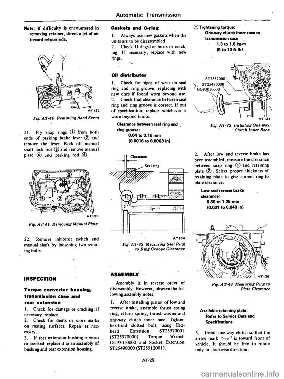
21
Pry
snap
rings
CD
from
both
ends
of
parking
brake
lever
@
and
remove
the
lever
Back
off
manual
shan
lock
nut
CID
and
remove
manual
plate
@
and
parking
rod
CID
Fig
AT
41
Rtmoving
Manual
Pl4tt
22
Remove
inhibitor
switch
and
manual
shaft
by
loosening
two
secur
ing
bolts
INSPECTION
Torque
converter
houslns
trensmlsslon
use
end
reer
extension
I
Check
for
damage
or
cracking
if
necessary
replace
2
Check
for
dents
or
score
marks
on
mating
surfaces
Repair
as
nee
essary
3
If
rear
extelUlion
bushing
is
worn
or
cracked
replace
it
an
mbly
of
bushing
and
rear
extension
housing
Automatic
Transmission
Geskots
end
Gorin
J
Always
use
new
gaskets
when
the
units
are
to
be
disassembled
2
Check
O
rings
for
burrs
or
crack
ing
If
necessary
replace
with
new
rings
011
distributor
I
Check
for
signs
of
wear
on
seal
ring
and
ring
groove
replacing
with
new
ones
if
found
worn
beyond
use
2
Check
that
clearance
between
seal
ring
and
ring
groove
is
correct
If
out
of
specification
replace
whichever
is
worn
beyond
limits
Clearence
1
n
58el
ring
end
ring
groove
0
04
to
0
16
mm
0
0016
to
0
0063
in
Clearance
Seal
ring
0
o
ii
J
0
1
FI
AT13
Fig
AT
42
Mea
uring
Seal
Ring
to
Ring
Groove
Clearance
ASSEMBLY
Assembly
is
in
reverse
order
of
disassembly
However
observe
the
fol
lowing
assembly
notes
After
installing
piston
of
low
and
reverse
Drake
assemble
thrust
spring
ring
return
spring
thrust
washer
and
one
way
clutch
inner
race
Tighten
hex
head
slotted
bolt
using
Hex
head
Extension
ST2SS7000J
ST2SS70000
Torque
Wrench
GG930JOOOO
and
Socket
Extension
ST2S490000
ST2SSI200J
AT
29
J
Tightening
torque
One
way
clutch
inner
race
to
transminion
case
1
3
to
1
8
kg
m
9
to
13
ft
b
ST25570001
h
ST25490000
GG9
30
10000
Fig
AT
43
1
lalli
ll
One
way
Clutch
Inner
Race
2
After
low
and
reverse
brake
has
been
assembled
measure
the
clearance
between
snap
ring
CD
and
retaining
plate
@
Select
proper
thickness
of
retaining
plate
to
give
correct
ring
to
plate
clearance
Low
and
revene
br
ke
de
r
nce
0
80
to
1
25
mm
0
031
to
0
049
in
Fig
A
T
44
Measuring
Ring
to
Plate
Clearance
Available
retaining
plete
Refer
to
Service
Oeta
and
Specifications
3
Install
one
way
clutch
so
that
the
arrow
mark
4
is
toward
front
of
vehicle
It
should
be
free
to
rotate
only
in
clockwise
direction
Page 282 of 548
ITU
lmQO
d
fJ
AT137
Fig
A
T
45
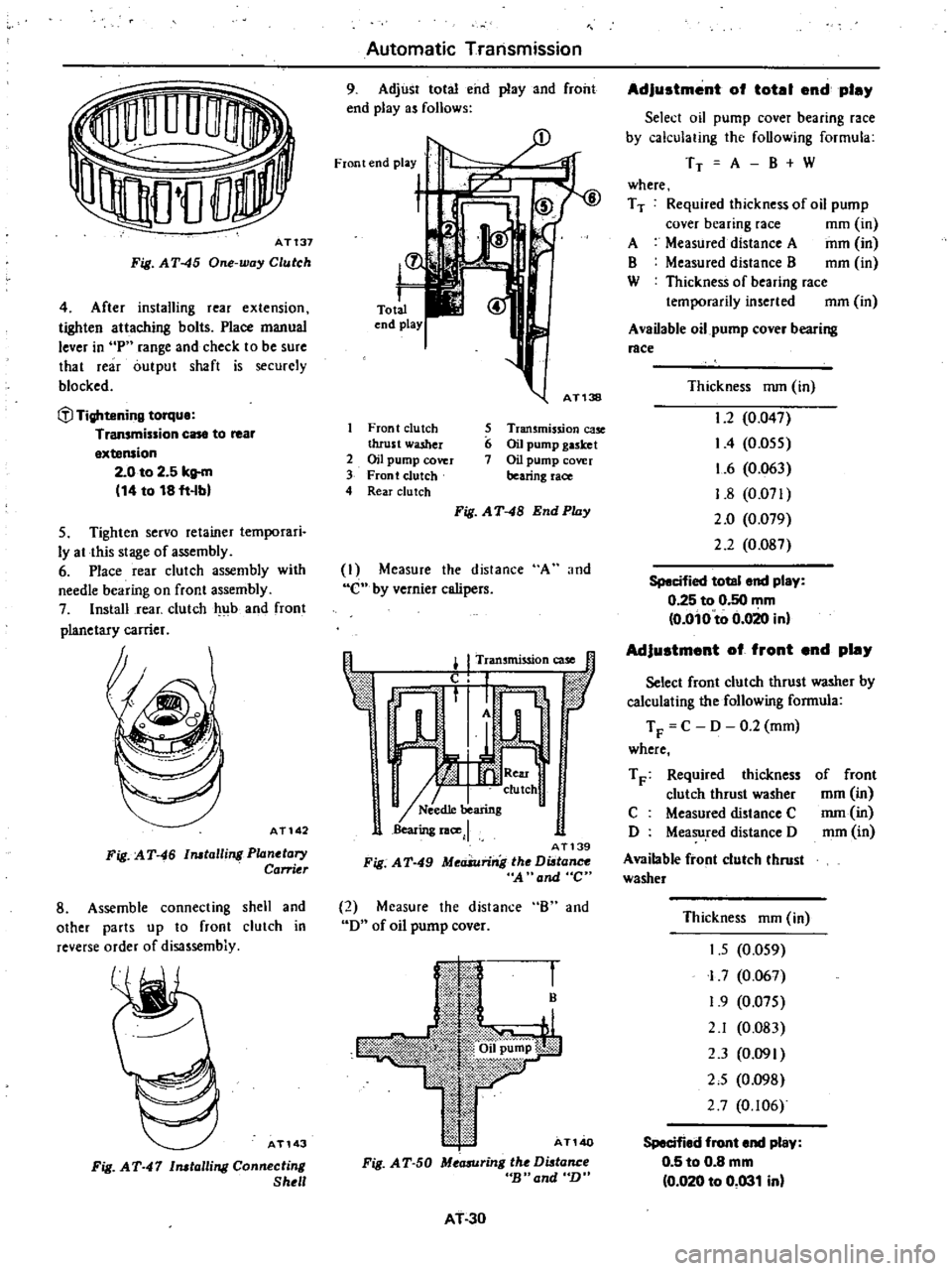
One
way
Cluleh
4
After
installing
rear
extension
tighten
attaching
bolts
Place
manual
lever
in
P
range
and
check
to
be
sure
that
rear
outpul
shaft
is
securely
blocked
fl
Tightening
torque
Transmission
case
to
rear
extension
2
0
to
2
5
kg
m
14
to
18
fHbl
5
Tighten
servo
retainer
temporari
Iy
at
this
stage
of
assembly
6
Place
rear
clutch
assembly
with
needle
bearing
on
front
assembly
7
Install
rear
clutch
4
lb
and
front
planetary
carrier
AT142
Fig
AT
46
talling
Planetary
Carrier
8
Assemble
connecting
shell
and
other
parts
up
to
front
clutch
in
reverse
order
of
disassembiy
AT143
Fig
AT
47
talling
Canneetin
Shell
Automatic
Transmission
9
Adjust
total
end
play
and
front
end
playas
follows
Front
end
play
t
Zl
L
r
Total
end
play
AT138
Front
clutch
5
Transmission
ca5e
thrust
washer
6
Oil
pump
gasket
2
OH
pump
cover
7
Oil
pump
cover
3
Front
clutch
bearing
race
4
Rear
clu
tch
Fig
AT
48
End
Play
I
Measure
the
distance
A
and
C
by
vernier
calipers
I
I
Tran
mission
case
t
f
l
1
I
n
0
tic
r
1
A
W
I
I
II
clulch
I
N
ed1e
bearing
Bearing
lace
J
AT139
Fig
A
T
49
MeaSuring
the
Di
tance
A
and
C
2
Measure
the
distance
B
and
D
of
oil
pump
cover
B
AT140
Fig
A
T
50
Measuring
the
Di
tance
cB
and
n
AT
30
Adjustment
of
totel
end
pley
Select
oil
pump
cover
bearing
race
by
calculating
thc
following
formula
TT
A
B
W
where
T
T
Required
thickness
of
oD
pump
cover
bearing
race
mm
in
A
Measured
distance
A
mm
in
B
Measured
distance
B
mm
in
W
Thickness
of
bearing
race
temporarily
inserted
mm
in
A
vaDable
oil
pump
cover
bearing
race
Thickness
nun
in
1
2
0
047
I
4
0
055
1
6
0
063
1
8
0
071
2
0
0
079
2
2
0
Og7
Specified
totel
end
play
0
25
to
0
50
mm
o
oio
to
0
020
inl
Adjustment
of
front
end
pley
Select
front
clutch
thrust
washer
by
calculating
the
following
formula
T
F
C
D
0
2
mm
where
T
F
Required
thickness
clutch
thrust
washer
C
Measured
distance
C
D
Measu
red
distance
D
Available
front
clutch
thrust
washer
of
front
mm
in
nun
in
mm
in
Thickness
mm
in
1
5
0
059
I
7
0
067
1
9
0
075
2
1
0
083
2
3
0
091
2
5
0
098
2
7
0
106
Specified
front
end
pley
0
5
to
0
8
mm
0
020
to
0
031
inl
Page 283 of 548
Note
L
C
llTect
thid
ness
of
bearing
race
end
thrust
washer
is
always
the
one
which
is
nearest
the
calculated
one
b
InsteJled
thid
noss
of
oil
pump
gasket
is
0
4
mm
0
016
in
10
Check
to
b
sure
that
brake
servo
piston
moves
freely
For
detailed
procedure
refer
to
page
AT
33
for
Servo
Piston
Use
care
to
prevent
piston
from
coming
out
of
place
dur
ing
testing
since
servo
retainer
is
not
tightened
at
this
point
of
assembly
II
Make
sure
that
brake
band
strut
is
correctly
installed
Tighten
piston
stem
Back
off
two
full
turns
end
secure
with
lock
nul
l
l
Tightening
torqUl
Piston
stem
1
2
to
1
5
kg
m
9
to
11
ft
lbl
Piston
tem
lock
nut
1
5
to
4
0
kg
m
11
to
29
ft
lbl
Available
diaphragm
rod
Distance
measured
L
mm
in
Under
25
55
1
0059
25
65
to
26
05
1
0098
to
1
0256
26
15
to
26
55
1
0295
to
1
0453
26
65
to
27
05
1
0492
to
1
0650
Over
27
15
1
0689
COMPONENT
PARTS
The
transmission
consists
of
many
all
parts
that
are
quite
alike
in
oonstruction
yet
machined
to
very
close
tolerances
When
disassembling
parts
be
sure
to
place
them
in
order
in
part
rack
so
they
can
be
restored
in
the
unit
in
their
proper
positions
It
is
also
very
important
to
perform
func
lional
test
whenever
it
is
designated
Automatic
Transmission
12
After
inhibitor
switch
is
in
stalled
check
to
be
sure
that
it
op
erates
properly
in
each
range
For
detailed
procedure
refer
to
page
AT
40
for
Checking
and
Adjusting
lnhibi
tor
Switch
13
Check
the
length
L
between
case
end
to
rod
end
of
vacuum
throttle
valve
fully
pushed
in
Then
select
adequate
diaphragm
rod
of
corre
sponding
measured
length
1
11f1
n
1
11
1
1
f
c
dllidf
i
L
AT145
Fig
A
T
51
M
asuring
the
Dutance
L
Diaphragm
rod
length
mm
in
29
0
1
142
295
1
161
30
0
I
181
30
5
1
201
31
0
1
220
FRONT
CLUTCH
Dl
mbly
@
@
@
I
Piston
2
Coil
spring
3
Front
clutch
drum
4
Dished
plate
5
Driven
plate
I
6
R
I
etammg
plate
7
Snap
ring
8
Drive
plate
A
T146
9
Spring
retainer
10
Snip
ring
Fig
AT
52
Section
1
View
of
Fronl
Clulch
AT31
I
Pry
off
snap
ring
j
with
a
suitable
screwdriver
or
a
pair
of
pliers
Remove
a
retaining
plate
@
drive
plate
@
driven
plate
@
and
dished
plate
@
in
the
order
listed
as
shown
in
Fig
AT
52
2
Compress
clutch
springs
using
Clutch
Spring
Compressor
ST25420001
or
ST25420000
Re
move
snap
ring
@
from
spring
reo
tainer
using
Snap
Ring
Remover
ST25320001
Fig
AT
53
Removing
Snap
Ring
Note
When
Clutch
Spring
Compres
sor
ST2S420000
is
to
be
used
cut
the
toe
tips
of
three
legs
by
a
grinding
wheel
L
J
t
E
5
Eo
U
0
20mm
0
79
in
Cut
off
hatched
portion
Fig
A
T
54
Modifying
Coil
Spring
Compressor
AT
148
3
Take
out
spring
retainer
@
and
spring
2
See
Fig
AT
52
4
Blowout
piston
by
directing
a
jet
of
air
into
hole
in
clutch
drum
AT149
Fig
A
T
55
Blowing
Out
Piolon
Page 288 of 548
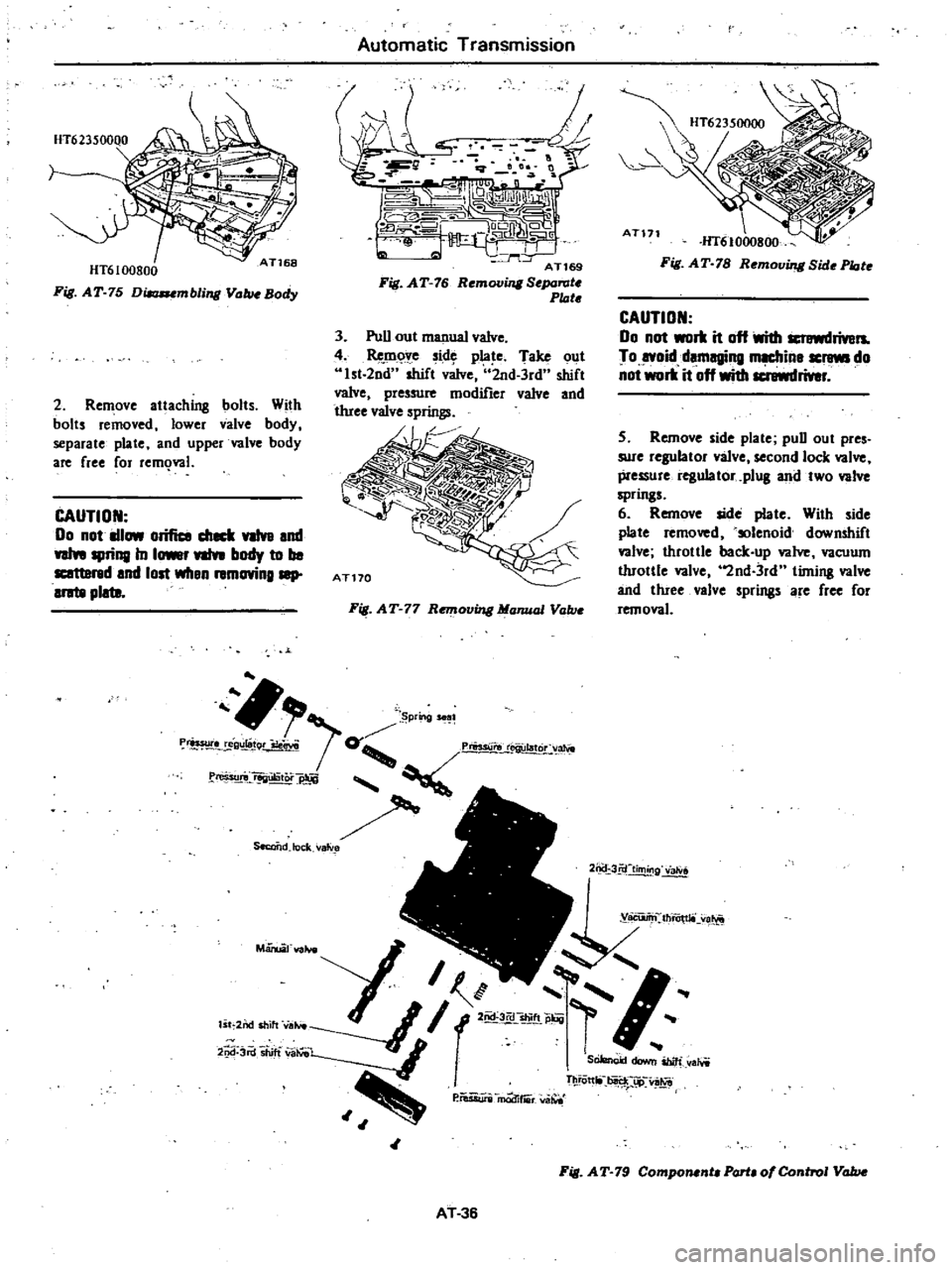
HT6100800
Fig
AT
75
Dilaaumbling
ValwBady
2
Remove
attaching
bolts
With
bolts
removed
lower
valve
body
separate
plate
and
upper
valve
body
are
free
for
rem
wl
CAUTION
00
not
IIlow
orifice
c111C1l
VIlv8
end
weIn
spring
In
1
nIn
body
to
be
I
and
lost
wilen
removinglllp
aratll
plata
Automatic
Transmission
Sf
3
Pull
out
manual
valve
4
Remove
side
plate
Take
out
Ist
2nd
shift
dve
2nd
3rd
shift
valve
pressure
modifier
valve
and
Wee
valve
springs
Fig
AT
77
Remouing
Manual
Vallie
r
p
g
1
Prasur
e
ul8t
m
g
qrJ
0
ew
o
afW
e
f
rio
UIiltOi
SeccQdJock
V81V
AT171
HT61000800
Fig
AT
78
Remouing
Bide
Plote
CAUTION
00
not
work
it
off
With
rivers
To
syoid
damaging
m
in8
screws
do
not
work
it
off
with
screwdriver
5
Remove
side
plate
pull
out
pres
sure
regulator
valve
second
lock
valve
pressure
regulator
plug
and
two
valve
springs
6
Remove
side
plate
With
side
plate
removed
solenoid
downshift
valve
throttle
back
up
valve
vacuum
throttle
valve
2nd
3rd
timing
valve
and
three
valve
springs
are
free
for
removal
2ncr
3fiftiming
2
Jd
3rd
shift
WiIVeL
q
SOJe
nod
00
ibiIi
aMi
P
iWWi
m
d
fiii
va
iOtt
tii
jJ
v
Fig
AT
79
ComponentaPartaofeontrol
Value
AT
36
Page 289 of 548
Automatic
Transmission
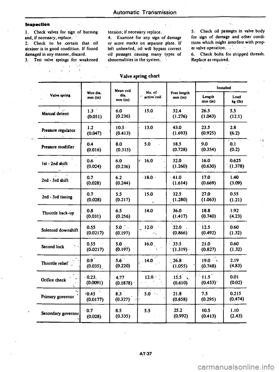
Inspection
I
Check
valves
for
sign
of
burning
tension
if
necessary
replace
5
Check
oil
passages
in
valve
body
and
if
necessary
replace
4
Examine
for
any
sign
of
damage
for
sign
of
damage
and
other
condi
2
Check
to
be
certain
that
oil
or
score
marks
on
separate
plate
If
tions
which
might
interfere
with
prop
strainer
is
in
good
condition
If
found
left
unheerlcd
oil
will
bypass
correct
er
valve
operation
damaged
in
any
manner
discard
oil
passages
causing
many
types
of
6
Check
bolts
for
stripped
threads
3
Test
valve
springs
for
weakened
abnormalities
in
the
system
Replace
as
required
Valve
spring
chart
Mean
coil
Installed
Wiredia
No
of
Free
length
Valve
sprma
mm
in
dia
active
coil
mm
in
Length
Load
mm
in
mm
in
kg
lbl
Manual
detent
1
3
6
0
15
0
32
4
26
5
5
5
0
051
0
236
1
276
1
043
12
1
Pressure
regulator
1
2
10
5
13
0
43
0
23
5
2
8
0
047
0
413
1
693
0
925
6
2
Pressure
modifier
0
4
8
0
5
0
18
5
9
0
0
1
0
01
6
0
315
0
728
0
354
0
2
2nd
shift
0
6
6
0
f
16
0
32
0
16
0
0
625
1st
0
024
0
236
1
260
0
630
1
378
2nd
3rd
shift
0
7
6
2
18
0
41
0
17
0
1
40
0
028
0
244
1
614
0
669
3
09
2nd
3rd
timing
0
7
5
5
15
0
32
5
27
0
0
55
0
028
0
217
1
280
1
063
1
21
Throttle
back
up
0
8
6
5
14
0
36
0
18
8
1
92
0
031
0
256
1417
0
740
4
23
Solenoid
downshift
0
5
5
0
12
0
22
0
12
5
0
60
0
0217
0
197
0
866
0
492
1
32
Second
lock
0
55
5
0
16
0
33
5
21
0
0
60
0
0217
0
197
1
319
0
827
1
32
Throttle
relief
0
9
5
6
14
0
26
8
19
0
2
19
0
035
0
220
1
055
0
74g
4
83
Orifice
check
0
23
4
77
12
0
15
5
11
5
om
0
0091
0
lg78
0
610
0
453
0
02
Primary
governor
0
45
8
3
5
0
21
8
7
5
0
215
0
0177
0327
0
858
0
295
0
474
Secondary
governor
0
7
8
5
5
5
25
2
10
5
1
10
0
028
0
335
0
992
0
413
2
43
T
37
Page 302 of 548

Oldel
Others
Automatic
Transmission
Test
item
4
Shift
down
Or
O
O
5
Shift
down
Or
I
1
6
Shift
down
0
2
7
Shift
up
1
1
8
Shift
up
or
down
when
start
ing
in
2
ranae
9
Parking
Abnormal
shock
oil
leakage
Procedure
Check
vehicle
speeds
and
engine
rpm
in
shifting
down
from
3rd
2nd
1st
sequentiaUy
while
coasting
with
accelerater
pedal
released
in
0
range
and
engine
vacuum
pressure
of
about
450
mmHg
17
72
inHg
Check
for
shifti
ng
do
n
I
I
nd
engine
blaking
and
further
for
shifting
down
I
I
and
engine
braking
tel
shifting
the
leyer
into
I
range
with
the
accelerator
pedal
released
and
the
engine
vacuum
pressure
of
0
mmHg
0
inHg
while
driving
at
about
50
km
h
30
MPH
in
0
range
Check
for
quick
shifting
down
OJ
2
and
engine
braking
after
shifting
the
lever
into
2
range
while
driving
at
about
50
km
h
30
MPH
in
0
range
Further
chec
for
locking
of
the
transmission
i
2nd
gear
ratio
regardless
of
vehicle
sPeed
Check
for
failure
of
the
transmission
to
shift
up
during
acceleration
when
starting
in
range
Check
the
transmission
for
not
shifting
up
or
down
during
acceleration
or
deceleration
when
starting
in
2
range
Confirm
that
yehicle
will
notmoye
on
grade
when
shifting
to
pn
range
Enter
into
record
conditions
observed
durq
these
lests
such
as
gear
noise
abnormal
clutch
noise
and
acceleration
performance
AT
50
Page 304 of 548

Automatic
Transmission
Low
eve
se
br
ke
Number
of
drive
plates
N
wnbe
of
driven
plates
Clearance
Thickness
of
retaining
plate
ml11
in
mm
in
3
3
0
80
to
1
25
0
031
to
0
049
15
8
0
622
16
0
0
630
16
2
0
638
16
4
0
646
16
6
0
654
16
8
0
661
Brake
band
Piston
size
Big
dia
Small
dia
mm
in
60
236
40
1
57
Control
valve
assembly
Stamped
mark
on
strainer
Non
California
models
Sedan
and
Hatchback
LEA
California
models
All
models
and
Non
California
models
Wagon
LRJ
Governor
assembly
Stamped
mark
on
governor
body
35
Stall
revolution
AI4
engine
AI5
engine
rpm
1
900
t02
200
1
850
to
2
150
TI
htenln
torque
Drive
plate
to
crankshaft
AI4
AI5
kg
m
ft
lb
Drive
plate
to
torque
converter
Converter
housing
to
engine
Hexagon
bolts
with
washer
Hexagon
flange
head
bolts
Transmission
case
to
converter
housing
Oil
pan
to
transmission
cue
Servo
piston
retainer
to
transmission
case
Piston
stem
when
adjusting
band
brake
Piston
stem
lock
nut
8
0
to
9
0
58
to
65
8
5
to
9
5
61
to
69
4
0
to
5
0
29
to
36
2
0
to
2
5
14
to
18
1
6
to
2
2
I2to
16
4
5
to
5
5
33
to
40
0
5
to
0
7
3
6
to
5
1
0
5
to
0
7
3
6
to
5
1
1
2
to
1
5
9
to
11
1
5
to
4
0
II
to
29
1
3
to
1
8
9
to
13
0
55
to
0
75
4
0
to
5
4
0
25
to
035
1
8
to
2
5
0
25
to
0
35
1
8
to
2
5
0
5
to
0
7
3
6
to
5
1
One
way
clutch
inner
race
to
transmission
case
Control
valve
body
to
transmission
case
Lower
valve
body
to
upper
valve
body
Side
plate
to
control
valve
body
Nut
for
control
valve
reamer
bolt
AT
52