DATSUN 210 1979 Service Manual
Manufacturer: DATSUN, Model Year: 1979, Model line: 210, Model: DATSUN 210 1979Pages: 548, PDF Size: 28.66 MB
Page 441 of 548
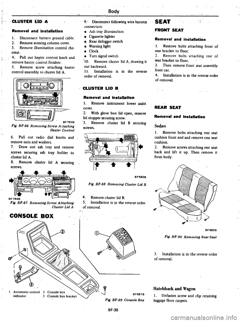
CLUSTER
I
IDA
Removal
and
installation
I
Disconnect
batterv
ground
cable
2
Remove
steering
column
cover
3
Remove
illumination
control
rhe
ostat
4
Pull
out
heater
control
knob
and
remove
heater
c
ntrol
finisher
5
Remove
screw
attaching
heater
control
assembly
to
cluster
lid
A
nQ
lQ
Ii
tl
rffmfLu
O
r
BF783B
Fig
BF
86
Removing
Screw
A
Uoching
Heater
Control
6
Pull
out
radio
dial
knobs
and
remove
nuts
and
washers
7
Draw
out
ash
tray
and
remove
screws
securing
ash
tray
holder
to
cluster
lid
A
B
Remove
cluster
lid
A
securing
screws
1
G808
iS
Ill
1
CJy
BF7848
Fig
BF
87
Remooing
Screw
Attaching
Cluster
Lid
A
CONSOLE
BOX
@
01
Automatic
control
2
Console
box
indicator
3
Console
box
bracket
Body
9
Disconnect
following
wire
harness
connectors
Ash
tray
illumination
Cigarette
lighter
Rear
defogger
switch
Warning
light
Clock
Turn
signal
switch
10
Remove
cluster
lid
A
drawing
it
out
backward
11
Installation
is
in
the
reverse
order
of
removal
CLUSTER
LID
B
Removal
and
Installation
I
Remove
instrument
lower
assist
cover
2
With
glove
box
lid
open
remove
lid
stopper
securing
screw
3
Remove
cluster
lid
B
securing
screws
i
i
ll
r
II
I
BF580B
Fig
BF
88
Removing
Cluster
Lid
B
4
Remove
cluster
lid
B
5
Installation
is
in
the
reverse
order
of
removal
J
BF581
B
Fig
BF
89
Console
Bo
SF
30
SEAT
FRONT
SEAT
Removal
and
installation
I
Remove
bolts
attaching
front
of
seat
bracket
to
floor
2
Remove
bolts
attaching
rear
of
seat
bracket
to
floor
3
Then
remove
front
seat
assembly
from
car
4
Installation
is
in
the
reverse
order
of
removal
REAR
SEAT
Removal
and
Installation
Sedan
I
Remove
bolts
attaching
rear
seat
cushion
front
end
and
remove
rear
seat
cushion
2
Remove
screws
attaching
rear
seat
back
and
lift
it
up
Then
remove
it
from
body
f
I
8F5828
Fig
BF
90
Removing
Rear
Seat
3
Installation
is
in
the
reverse
order
of
removaL
Hatchback
and
Wagon
I
Unfasten
screw
and
clip
retaining
luggage
floor
carpets
Page 442 of 548
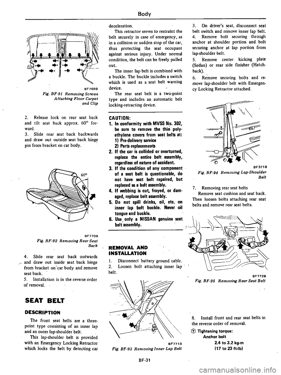
Z
jJ
BF769B
Fig
BF
91
Removing
Screws
Attaching
Floor
Carpet
and
Clip
2
Release
lock
on
rear
seat
back
and
tilt
seat
back
approx
600
for
ward
3
Slide
rear
seat
back
backwards
and
draw
out
outside
seat
back
hinge
pin
from
bracket
on
car
body
BF770B
Fig
BF
92
Removing
Rear
Seat
Back
4
Slide
rear
seat
back
outwards
and
draw
out
inside
seat
back
hinge
from
bracket
on
car
body
and
remove
seat
back
S
Installation
is
in
the
reverse
order
of
removal
SEAT
BELT
DESCRIPTION
The
front
seat
belts
are
a
three
point
type
consisting
of
an
inner
lap
and
an
outer
lap
shoulder
belt
This
lap
shoulder
belt
is
provided
with
an
Emergency
Locking
Retractor
which
locks
the
belt
by
detecting
car
Body
deceleration
This
retractor
serves
to
restraint
the
belt
securely
in
case
of
emergency
as
in
a
collision
or
sudden
stop
of
the
car
thus
protecting
the
seat
occupant
against
serious
injury
Under
normal
condition
the
belt
can
be
freely
pulled
out
The
inner
lap
belt
is
combined
with
a
buckle
The
buckle
includes
a
switch
which
is
used
as
a
seat
belt
warning
device
The
rear
seat
belt
is
a
two
point
type
and
includes
an
automatic
belt
locking
retracting
device
CAUTION
1
In
conformity
with
MVSS
No
302
be
sure
to
remove
the
thin
poly
ethylene
covers
from
seat
belts
at
1
Pre
delivery
service
2
Parti
replacements
2
If
the
car
is
collided
or
ovarturned
replace
the
entire
belt
assembly
regardless
of
nature
of
accident
3
If
the
condition
of
any
component
of
a
seat
belt
is
questionable
do
not
have
seat
belt
repaired
but
raplaced
as
a
belt
assembly
4
If
webbing
is
cut
frayed
or
dam
aged
replace
belt
assembly
5
Do
not
spill
drinks
oil
etc
on
inner
lap
belt
buckla
Naver
oil
tongue
and
buckle
6
Use
only
a
NISSAN
genuina
seat
belt
assembly
REMOVAL
AND
INSTALLATION
I
Disconnect
battery
ground
cable
2
Loosen
bolt
attaching
inner
lap
belt
BF771B
Fig
BF
93
Removing
Inner
Lap
Belt
BF
31
3
On
driver
s
seat
disconnect
seat
belt
switch
and
remove
inner
lap
belt
4
Remove
bolt
securing
through
anchor
at
shoulder
portion
and
bolt
securing
anchor
at
lap
portion
from
lap
shoulder
belt
5
Remove
center
kicking
plate
Sedan
or
rear
side
finisher
Hatch
back
6
Remove
securing
bolts
and
re
move
lap
shoulder
belt
with
Emergen
cy
Locking
Retractor
attached
BF311B
Fig
BF
94
Removing
Lop
Shoulder
Belt
7
Removing
rear
seat
belts
Remove
seat
cushion
and
seat
back
Then
loosen
bolts
attaching
rear
seat
belts
and
remove
rear
seat
belts
BF772B
Fig
BF
95
Removing
Rear
Seat
Belt
8
Install
front
and
rear
seat
belts
in
the
reverse
order
of
removal
iil
Tightening
torque
Anchor
bolt
2
4
to
3
2
kg
m
17
to
23
ft
Ibl
Page 443 of 548
INSPECTiON
OF
SEAT
BELT
SWITCH
The
contacts
of
seat
belt
switch
are
normally
closed
When
tongue
latches
buckle
the
tip
end
of
tongue
pushes
push
rod
to
open
the
switch
contacts
ROOF
TRIMMING
Removel
end
Inetelletlon
l
Remove
room
lamp
assist
grip
coat
hangers
inside
rearview
mirror
and
sun
visors
2
Remove
body
side
welts
and
re
move
roof
side
garnishes
and
tail
rail
garnish
3
Remove
rear
side
finishers
4
Draw
out
roof
headlining
from
windshield
weatherstrip
5
Installation
is
in
the
reverse
order
of
removal
Body
u
I
Disconnectbatter
y
ground
cable
2
Disconnect
seat
belt
switch
wire
harness
lape
belt
latches
buckle
and
go
on
when
it
unlatches
buckle
Replace
belt
assembly
if
necessary
Note
When
checking
seat
belt
switch
operation
make
sure
that
power
held
below
16
volts
and
13
mA
3
Check
seat
belt
switch
for
proper
operation
using
a
test
light
The
light
should
go
out
when
tongue
of
outer
TRIM
AND
MOLDING
f
BODY
SIDE
TRIM
AND
MOLDING
SEDAN
T
S
Tail
rail
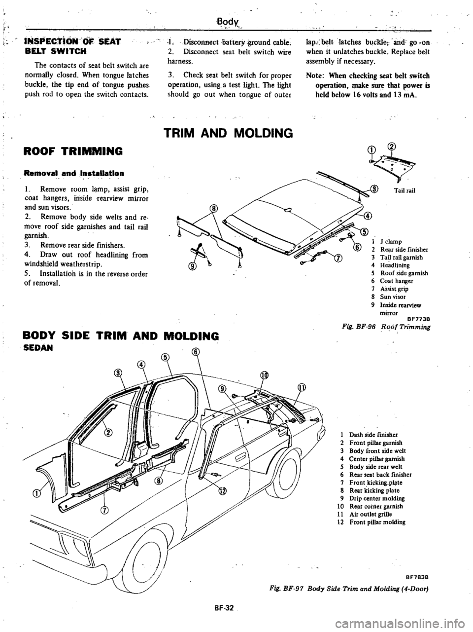
1
J
clamp
2
Rear
side
finisher
3
Tailrail
garnish
4
Headlining
5
Roof
side
garnish
6
Coat
hanger
7
Assist
grip
8
Sun
visor
9
Inside
rearview
mirror
BF173B
Fig
BF
96
Roof
Trimming
1
Dash
side
finisher
2
Front
pillar
garnish
3
Body
front
side
welt
4
Center
pillar
garnish
5
Body
side
rear
welt
6
Rear
seat
back
finisher
7
Front
kicking
plate
8
Rear
kicking
plate
9
Drip
center
molding
10
Rear
comer
garnish
11
Air
outlet
grille
12
Front
pillar
molding
Fig
BF
97
Body
Side
Trim
ond
Molding
4
Door
BF783B
BF
32
Page 444 of 548

Body
f
9
Fig
BF
98
side
finisher
5
Rear
t
back
fini
her
6
Rear
sea
late
7
Front
kickmg
p
k
king
plate
8
Rear
Ie
d
rear
molding
9
Drip
cente
o
r
garnish
10
Rear
Sld
r
molding
11
Front
p
Iding
fender
mo
12
Rear
BF784B
d
Molding
2
Door
Body
Sid
Trim
an
h
side
finisher
1
Das
h
llargarms
2
Front
pi
de
welt
3
Body
front
51
h
ilIargamls
4
Center
p
HATCHBACK
50
5
1
Dash
side
finishe
h
ilJargarms
2
Front
p
de
welt
3
Body
I
4
5
6
7
8
9
Luggage
rear
finis
er
10
liar
moldmg
11
Fropt
p
r
molding
12
Drip
cent
d
er
garnish
13
Lyggage
f1
or
boar
Rear
covslde
finisher
de
ollar
cover
Luggage
14
Lo
pi
Iding
are
wheel
cover
15
Rear
fender
o
ontkICkill8
plate
16
Air
out1etgrd
molding
k
g
plate
rtel
WlD
Rear
klc
In
17
Qua
8F7878
d
Imlsher
Rear
SI
e
nd
Molding
Side
Trim
a
Fig
BF
99
Body
BF
33
Page 445 of 548

Body
WAGON
6
I
Da
h
side
fInisher
2
Front
pillar
garnish
3
Body
front
side
welt
4
Center
pillar
garnish
5
Body
rear
side
welt
6
Luggage
side
upper
f
misher
7
Front
IticIting
plate
8
Rear
kicking
plate
9
Luggage
side
lower
rmi
Jher
10
Rear
window
welt
II
Luggage
rear
fini3her
12
Drip
center
and
rear
moldins
13
Air
outlet
grille
14
Rear
Cender
moldins
15
Luggage
floor
board
16
Front
pillar
moldins
8F7748
Fig
BF
IOO
Body
Side
Trim
and
Molding
SPECIAL
SERVICE
TOOLS
I
Kent
Moore
No
I
Kent
Moore
No
Tool
number
tool
name
Reference
page
or
Fis
No
Tool
number
tool
name
Reference
page
or
FiB
No
ST08800000
Sucker
ST088
10000
Caulking
hand
gun
cf0
FIg
BF
55
Fig
BF
67
Page
BF
22
Page
BF
23
Fig
BF
70
BF
34
Page 446 of 548
DATSUN
210
Model
8310
Series
SECTIONBE
BODY
ELECTRICAL
SYSTEM
CONTENTS
BODY
ELECTRICAL
WIRING
DESCRIPTION
FUSE
AND
FUSIBLE
LINK
WIRING
WIRING
HARNESS
LOCATION
OF
ELECTRICAL
UNIT
ELECTRICAL
UNIT
OF
LIGHTING
SYSTEM
BULB
SPECIFICATIONS
REMOVAL
AND
INSTALLATION
For
lamp
IGNITION
SWITCH
COMBINATION
SWITCH
ILLUMINATION
CONTROL
UNIT
AIMING
ADJUSTMENT
ELECTRICAL
UNIT
OF
SIGNAL
SYSTEM
BE
12
TURN
SIGNAL
SWITCH
BE
12
HORN
RELAY
BE
12
HAZARD
SWITCH
BE
12
STOP
LAMP
SWITCH
BE
12
BACK
UP
LAMP
SWITCH
BE
12
DOOR
SWITCH
BE
12
METERS
AND
GAUGES
BE
13
COMBINATION
METER
BE
13
TACHOMETER
BE
14
FUEL
LEVEL
AND
WATER
TEMPERATURE
INDICATOR
SYSTEM
BE
14
WARNING
SYSTEM
BE
15
CHARGE
WARNING
SYSTEM
BE
15
BRAKE
WARNING
SYSTEM
BE
15
BE
2
BE
2
BE
2
BE
4
BE
5
BE
8
BE
9
BE
9
BE
10
BE
10
BE
10
BE
11
BE
11
OIL
PRESSURE
WARNING
SYSTEM
SEAT
BELT
WARNING
SYSTEM
ELECTRICAL
ACCESSORIES
WINDSHIELD
WIPER
AND
WASHER
REAR
WINDOW
WIPER
AND
WASHER
CIGARETTE
LIGHTER
RADIO
CLOCK
REAR
WINDOW
DEFOGGER
STARTING
SYSTEM
For
automatic
transmission
models
HEATER
DESCRIPTION
AIR
FLOW
REMOVAL
AND
INSTALLATION
ADJUSTING
HEATER
CONTROL
DISASSEMBLY
AND
ASSEMBLY
OF
HEATER
UNIT
INSPECTION
WIRING
DIAGRAMS
AND
TROUBLE
DIAGNOSES
ELECTRICAL
SYSTEM
BLOCK
DIAGRAM
FUSE
BLOCK
CIRCUIT
SUPPLY
ROUTING
LIGHTING
SYSTEM
SIGNAL
SYSTEM
METERS
AND
GAUGES
WARNING
SYSTEM
ELECTRICAL
ACCESSORY
SYSTEM
HEATER
BE
15
BE
15
BE
17
BE
17
BE
18
BE
20
BE
20
BE
21
BE
21
BE
23
BE
23
BE
23
BE
24
BE
26
BE
27
BE
27
BE
28
BE
29
BE
29
BE
30
BE
31
BE
36
BE
41
BE
44
BE
4B
BE
55
Page 447 of 548
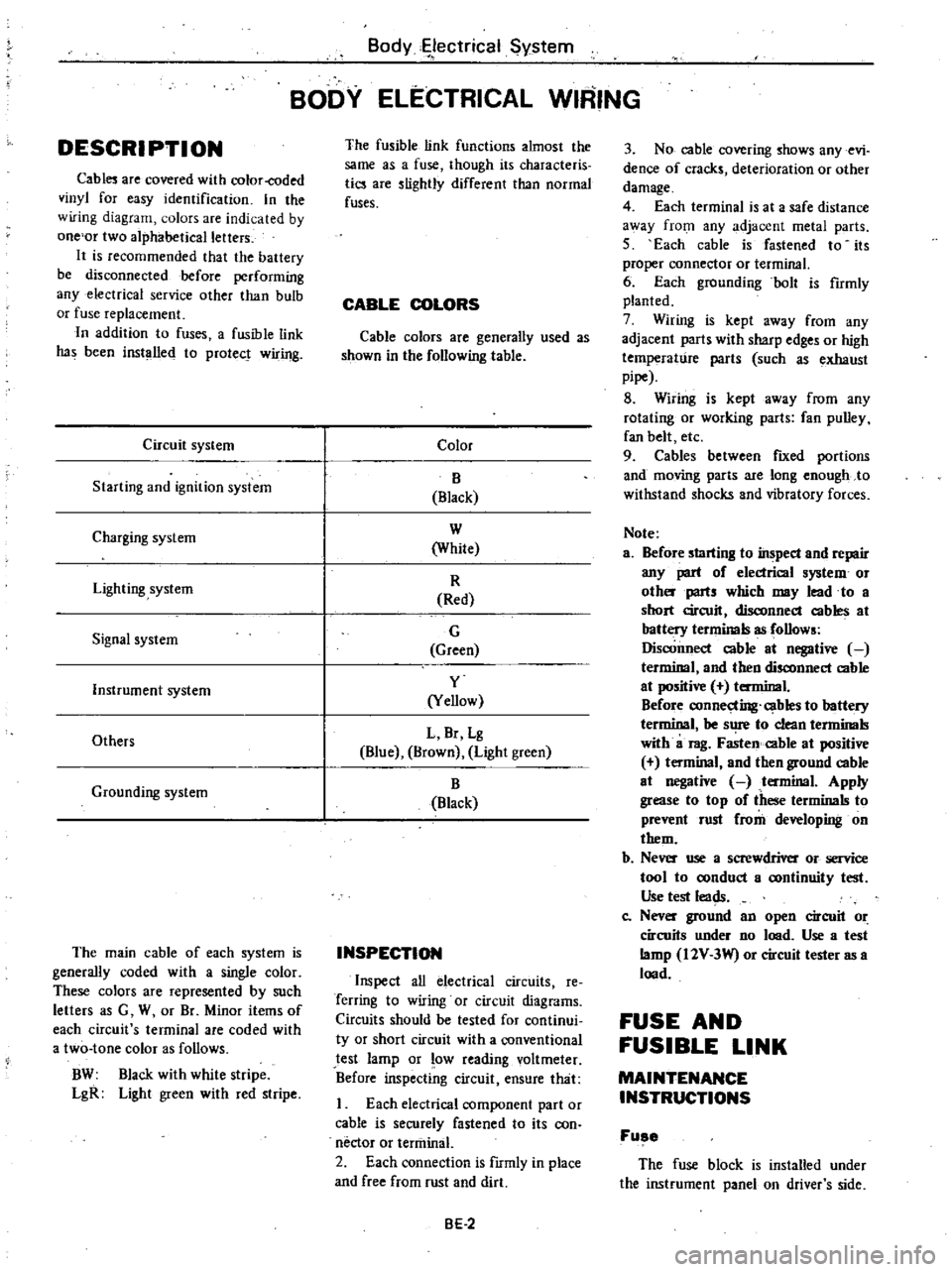
DESCRI
PTI
ON
Cabl
are
covered
with
color
coded
vinyl
for
easy
identification
In
the
wiring
diagram
olors
are
indicated
by
one
or
two
alphabetical
letters
It
is
recommended
that
the
battery
be
disconnected
before
performing
any
electrical
service
other
than
bulb
or
fuse
replacement
In
addition
to
fuses
a
fusible
link
has
been
installed
to
protect
wiring
Circuit
system
Starting
and
ignition
system
Charging
system
Lighting
system
Signal
system
Instrument
system
Others
Grounding
system
The
main
cable
of
each
system
is
generally
coded
with
a
single
color
These
colors
are
represented
by
such
letters
as
G
W
or
Br
Minor
items
of
each
circuit
s
terminal
are
coded
with
a
two
tone
color
as
follows
BW
Black
with
white
stripe
LgR
Light
green
with
red
stripe
Body
ectrical
System
BODY
ELECTRICAL
WIRING
The
fusible
link
functions
almost
the
same
as
a
fuse
though
its
characteris
tics
are
slightly
different
than
normal
fuses
CABLE
COLORS
Cable
colors
are
generally
used
as
shown
in
the
following
table
Color
B
Black
W
White
R
Red
G
Green
y
Yellow
L
Br
Lg
Blue
Brown
Light
green
B
Black
INSPECTION
Inspect
all
electrical
circuits
Ie
Terring
to
wiring
or
circuit
diagrams
Circuits
should
be
tested
for
continui
ty
or
short
circuit
with
a
conventional
test
lamp
or
low
reading
voltmeter
Before
inspecting
circuit
ensure
that
I
Each
electrical
component
part
or
cable
is
securely
fastened
to
its
con
nector
or
tenninal
2
Each
connection
is
fIrmly
in
place
and
free
from
rust
and
dirt
BE
2
3
No
cable
covering
shows
any
evi
dence
of
cracks
deterioration
or
other
damage
4
Each
terminal
is
at
a
safe
distance
3
Vay
from
any
adjacent
metal
parts
5
Each
cable
is
fastened
to
its
proper
connector
or
terminal
6
Each
grounding
bolt
is
fumly
planted
7
Wiring
is
kept
away
from
any
adjacent
parts
with
sharp
edges
or
high
temperature
parts
such
as
exhaust
pipe
8
Wiring
is
kept
away
from
any
rotating
or
working
parts
fan
pulley
fan
belt
etc
9
Cables
between
fIXed
portions
and
moving
parts
are
long
enough
to
withstand
shocks
and
vibratory
forces
Note
a
Before
starting
to
inspect
and
repair
any
part
of
electrical
system
or
oth
parts
which
may
lead
to
a
short
circuit
disconnect
cables
at
battery
terminals
as
follows
Disconnect
cable
at
negative
terminal
and
then
disconnect
cable
at
positive
terminal
Before
connecting
cables
to
battery
terminal
be
s
1
to
clean
tenninals
with
a
rag
Fasten
cable
at
positive
t
minal
and
then
ground
cable
at
negative
tenninal
Apply
grease
to
top
of
these
terminals
to
prevent
rust
from
developing
on
them
b
Ne
use
a
screwdriver
or
service
tool
to
oonduct
a
oontinuity
test
Use
test
leads
Co
Nev
ground
an
open
circuit
or
circuits
under
no
lood
Use
a
test
lamp
I2V
3W
or
circuit
tester
as
a
lood
FUSE
AND
FUSIBLE
LINK
MAINTENANCE
INSTRUCTIONS
Fuse
The
fuse
block
is
installed
under
the
instrument
panel
on
driver
s
side
Page 448 of 548

When
for
one
reason
or
another
fuse
has
melted
use
systematic
proce
dure
to
check
and
eliminate
cause
of
problem
before
installing
new
fuse
Note
a
If
fuse
is
blown
be
sure
to
elimi
nate
cause
of
problem
before
in
stalling
new
fuse
b
Use
fuse
of
specified
rating
Never
use
fuse
of
more
than
specified
rating
c
Check
condition
of
fuse
holders
If
much
rust
or
dirt
is
found
thereon
clean
metal
parts
with
fine
grained
sandpaper
until
proper
metal
to
metal
contact
is
made
Poor
contact
in
any
fuse
holder
will
often
lead
to
voltage
drop
or
heat
ing
in
the
circuit
and
could
result
in
improper
circuit
operation
Body
Electrical
System
W
BE1100
Fig
BE
l
FU
e
Block
Fusible
link
Fusible
link
protects
starting
he
d
lamp
ignition
and
charge
circuits
and
wiring
between
fuse
and
fusible
link
BE1110
Fig
BE
2
Fusible
Link
BE
3
CAUTION
a
If
fusible
link
should
melt
it
is
possible
that
critical
circuit
power
supply
or
large
current
carrying
circuit
is
shorted
In
such
a
case
carefully
check
and
eliminate
cause
of
problem
b
Never
wrap
periphery
of
fusible
link
with
vinyl
tape
Extreme
care
should
be
taken
with
this
link
to
ensure
that
it
does
not
come
into
contact
with
any
other
wiring
har
ness
or
vinyl
or
rubber
parts
A
melted
fusible
link
can
be
detect
ed
either
by
visual
inspection
or
by
feeling
with
finger
tip
If
its
condition
is
questionable
use
circuit
tester
or
test
lamp
as
required
to
conduct
continuity
test
This
continuity
test
can
be
performed
in
the
same
manner
as
for
any
conventional
fuse
Page 449 of 548
Body
Electrical
System
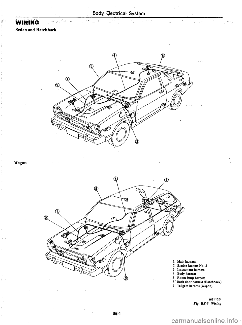
WIRING
Sedan
and
Hatchback
Wagon
2
1
Main
harness
2
Engine
harness
No
2
3
Instrument
harness
4
Body
harness
5
Room
tamp
harness
6
Back
door
harne
ls
Hatchback
7
Tailgate
harness
Wagon
BEl12D
Fig
BE
3
Wiring
BE4
Page 450 of 548
m
c
n
to
l
l
I
g
iF
0
1
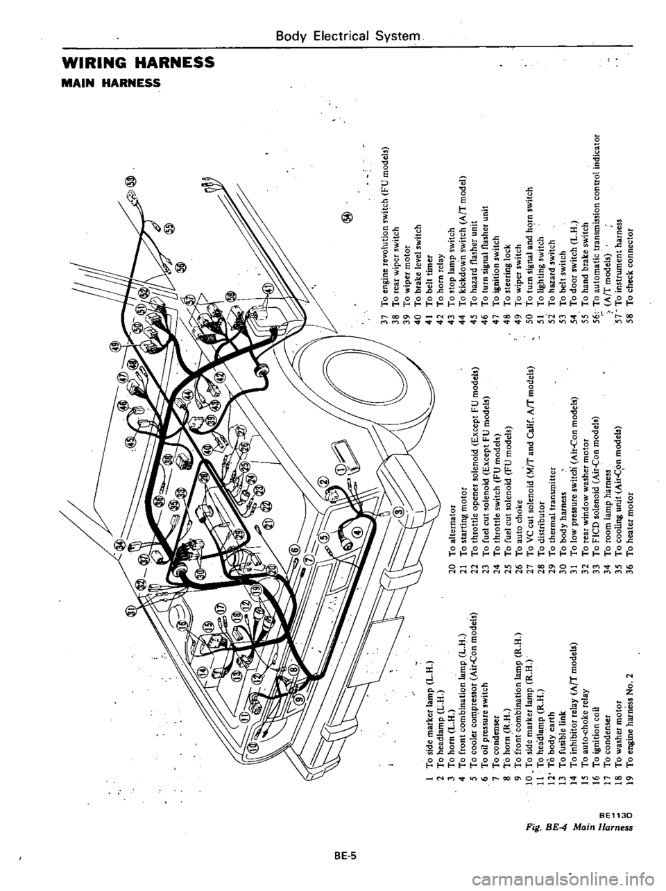
To
side
marker
lamp
L
H
2
To
headlamp
L
H
3
To
horn
L
H
4
To
front
combination
lamp
L
H
5
To
cooler
co
pressor
Air
Con
models
6
To
oil
pressure
switch
7
To
condenser
8
To
horn
R
H
9
To
front
combination
la
t11p
R
H
10
To
side
marker
lamp
R
H
11
To
headlamp
R
H
12
To
body
earth
13
To
fusible
link
14
To
inhibitor
relay
AfT
model
15
To
aut6
choke
relay
16
To
ignition
coil
17
To
condenser
18
To
washer
motor
19
To
engine
harness
No
2
@
20
To
alternator
21
To
starting
motor
22
To
throttle
opener
solenoid
Except
FU
models
23
To
fuel
cut
solenoid
Except
FU
models
24
To
throttle
switch
FU
models
25
To
fuel
cut
solenoid
FU
models
26
To
auto
choke
27
To
VC
cut
solenoid
M
T
and
Calif
AfT
models
28
To
distributor
29
To
thermal
transmitter
30
To
body
harness
31
To
low
pressure
switcn
Air
Con
models
32
To
rear
window
washer
motor
33
To
FICO
solenoid
Air
Con
models
34
To
room
lamp
harness
35
To
cooling
unit
Air
C
on
models
36
To
heater
motor
37
To
engine
revolution
switch
FU
models
38
To
rear
wiper
switch
39
To
wiper
motor
40
To
brake
level
switch
41
To
belt
timer
42
To
horn
relay
43
To
stop
lamp
switch
44
To
kickdown
switch
AfT
model
45
To
hazard
flasher
unit
46
To
turn
signal
flasher
unit
47
To
ignition
switch
48
To
steering
lock
49
To
wiper
switch
50
To
turn
signal
and
hC
rn
switch
51
To
lighting
switch
5i
To
hazard
switch
53
To
belt
switch
54
To
door
switch
L
H
55
To
hand
brake
switch
56
To
automatic
transmission
control
indicator
AfT
models
57
To
instrument
harness
58
To
check
connector
I
0
i
a
z
Z
G
z
tIl
tIl
a
Z
Il
I
to
o
Co
m
16
n
n
OJ
1
3