torque DATSUN 210 1979 Workshop Manual
[x] Cancel search | Manufacturer: DATSUN, Model Year: 1979, Model line: 210, Model: DATSUN 210 1979Pages: 548, PDF Size: 28.66 MB
Page 218 of 548

Manual
Transmission
4
SPEED
TRANSMISSION
Model
F4W60L
t
f
@
4
Y
0
f
@
@
jj
J
QW
i
6
i
l
16
Rear
cxtension
dust
cover
with
oil
seal
17
Top
detecting
switch
TM281A
6
Tran
smi
sion
case
a
mbly
7
Filler
plug
8
Adapter
plate
9
Breather
10
Bearing
retainer
11
Rear
extension
dowel
pin
12
Reverse
lamp
sWitch
13
Rear
extension
assembly
14
Drain
plug
15
Retum
spring
bushing
Fig
MT
l
F4W60L
TrarwniuionClOMJ
Components
Tighteni
torque
kg
m
ft
lb
@
1
0
0
1
6
7
to
12
@
2
0
to
3
0
14
to
22
@
0
1
to
1
0
5
1
to
1
2
@
1
6102
2
12
to
16
@
2
5
to
4
0
18
to
29
itJ
2
0
to
3
5
141025
@
2
5
to
4
0
18
to
29
I8i
2
0
to
3
5
14
to
25
1
Front
cover
2
Front
cover
oil
seal
3
Front
cover
O
ring
4
Front
cover
adjusting
shim
5
Welch
plug
c
@
r
TM093A
1
Main
drive
bearing
2
Main
drive
gear
3
3rd
top
synchronizer
4
3rd
gear
mainshaft
5
Mainshaft
6
2nd
gear
mainmaft
7
ht
2nd
synchronizer
8
1
It
gear
mainshaft
9
Mainshaft
bearing
10
Reverse
gear
mainshaft
11
Counter
gear
assembly
12
Idler
gear
assembly
Fig
MT
2
F4W60L
Transmi8aion
G
CompoMnla
I
I
I
MT
2
Page 219 of 548

I
ht
2nd
fork
r
2
3rd
top
fork
rod
3
Reverse
fork
rod
4
Retaining
pin
5
I
t
2nd
shift
fork
6
3rd
top
shift
fork
7
Checking
ball
plug
8
Check
ban
spring
9
Check
ball
10
Interlock
plunger
11
S
topper
ring
12
Shift
rod
A
bracket
13
Reverse
shift
fork
14
Lock
pin
15
Striking
lever
Manual
Transmission
16
Striking
rod
17
Return
spring
plug
18
Reverse
check
spring
19
Return
pring
20
Plunger
21
D
ring
22
Stopper
pin
bolt
23
Striking
guide
assembly
24
Striking
guide
oil
seal
REMOVAL
To
dismount
transmission
from
the
car
proceed
as
follows
Disconnect
battery
ground
cable
2
Remove
console
box
and
detach
rubber
boots
if
so
equipped
3
Place
transmission
control
lever
in
neutral
position
and
remove
it
m
TM781
Fig
MT
4
Removing
Control
Lever
@
@
25
Control
lever
bushing
26
Expansion
plug
27
Control
pin
bushing
28
Control
arm
pin
29
Control
lever
o
Tightening
torque
kg
m
ft
lb
@
0
5
to
0
8
3
6
tn
5
8
@
1
3
to
1
7
9
to
12
Fig
MT
3
F4W60L
Tra11lmiBSion
Shift
Control
Components
TM094A
4
Jack
up
the
car
and
support
its
weight
on
safety
stands
Use
a
hy
draulic
hoist
or
open
pit
if
available
Make
sure
that
safety
is
insured
5
Disconnect
front
exhaust
tube
and
remove
bolt
securing
exhaust
mounting
bracket
from
exhaust
front
tube
side
6
Disconnect
wires
from
reverse
back
up
lamp
switch
7
Disconnect
speedometer
cable
from
rear
extension
At
the
same
time
removey
top
detecting
switch
if
so
equipped
8
Remove
propeller
shaft
Refer
to
Removal
Section
PO
Note
Plug
up
the
opening
in
the
rear
extension
to
prevent
oil
from
flow
ing
out
MT
3
9
Remove
clutch
operating
cylinder
from
transmission
case
10
Support
engine
by
placing
a
jack
under
oil
pan
with
a
wooden
block
used
between
oil
pan
and
jack
CAUTION
00
not
place
the
jack
under
the
oil
pan
drain
plug
11
Support
transmission
with
a
transmission
jack
12
Loosen
rear
engine
mount
se
curing
bolts
CD
temporarily
and
re
move
crossmember
mounting
bolts
V
Page 220 of 548
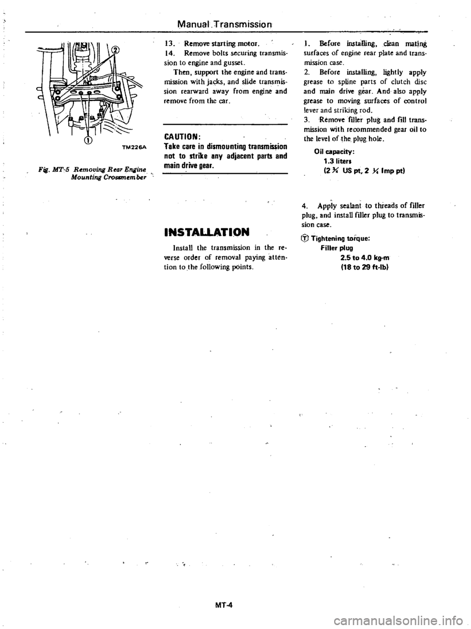
Fig
MT
5
Removing
Rear
1IIline
Mounting
Croamember
Manual
Transmission
13
Remove
starling
motor
14
Remove
bolts
securing
transmis
sion
to
engine
and
gusset
Then
support
the
engine
and
trans
mission
with
jacks
and
slide
trans
is
sion
rearward
away
from
engine
and
remove
from
the
car
CAUTION
Take
care
in
dismounting
trammission
not
to
strike
any
adjacent
parts
and
main
drive
gear
INSTAUATION
Install
the
transmission
in
the
re
verse
order
of
removal
paying
atten
tion
to
the
following
points
MT
4
I
Before
installing
cJean
mating
surfaces
of
engine
rear
plate
and
trans
mission
case
2
Before
installing
lightly
apply
grease
to
spline
parts
of
clutch
disc
and
main
drive
gear
And
also
apply
grease
to
moving
surfaces
of
control
lever
and
striking
rod
3
Remove
filler
plug
and
fill
trans
mission
with
recommended
gear
oil
to
the
level
of
the
plug
hole
Oil
capacity
1
3
liter
2
US
pt
2
Y
Imp
ptl
4
Apply
sealant
to
threads
of
filler
plug
and
install
fdler
plug
to
transmis
sion
case
IiJ
Tightening
torque
Filler
plug
2
5
to
4
0
klt
fll
18
to
29
ft
Ib
Page 226 of 548
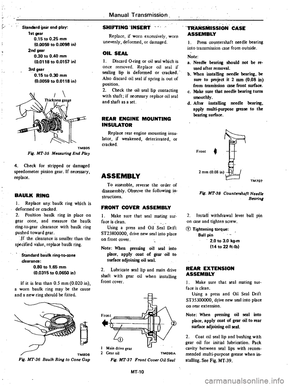
standard
gea
end
play
1st
gear
0
15
to
0
25
mm
0
0059
to
0
0098
inl
2nd
gear
0
30
to
0
40
mm
0
0118
to
0
0157
in
3rd
gear
0
15
to
0
30
mm
0
0059
to
0
0118
in
TMB05
Fig
MT
35
Me
uring
End
Phly
4
Check
for
stripped
or
damaged
speedometer
pinion
gear
If
necessary
replace
BAULK
RING
1
Replace
any
baulk
ring
which
is
deformed
or
cracked
2
Position
baulk
ring
in
place
on
gear
cone
and
measure
the
baulk
ring
to
gear
clearance
with
baulk
ring
pushed
toward
gear
If
the
clearance
is
smaller
than
the
specified
value
replace
baulk
ring
Standard
baulk
ring
to
cone
clearance
0
80
to
1
65
mm
0
0315
to
0
0650
inl
If
it
is
less
than
0
5
mm
0
020
in
a
worn
baulk
ring
may
be
the
cause
and
a
new
ring
should
be
fitted
TM806
Fig
MT
36
Baulh
Ring
10
Cone
Gap
Manual
Transmission
SHlFTING
INSERT
Replace
if
worn
excessively
worn
unevenly
deformed
or
damaged
OIL
SEAL
I
Discard
a
ring
or
oil
seal
which
is
once
removed
Replace
oil
seal
if
sealing
lip
is
deformed
Or
cracked
Also
discard
oil
seal
if
spring
is
out
of
position
2
Check
the
oil
seal
lip
contacting
with
shaft
if
necessary
replace
oil
seal
and
shaft
as
a
set
REAR
ENGINE
MOUNTING
INSULATOR
Replace
rear
engine
mounting
insu
lator
if
weakened
deteriorated
or
cracked
ASSEMBLY
To
assemble
reverse
the
order
of
disassembly
Observe
the
following
in
structions
FRONT
COVER
ASSEMBLY
I
Make
sure
that
seal
mating
sur
face
is
clean
Using
a
press
and
Oil
Seal
Drift
ST23800000
drive
new
seal
into
place
on
front
cover
Note
When
pressing
oil
seal
into
place
apply
coat
of
gear
oil
to
surface
adjoining
oil
seal
2
Lubricate
seal
lip
and
main
drive
shaft
with
gear
oil
when
installing
front
cover
Front
4
Main
drive
gear
2
Gear
oil
TM098A
Fig
MT
37
Fronl
Cover
Oil
Seal
MT10
TRANsMISSION
CASE
ASSEMBLY
1
Press
countershaft
needle
bearing
into
transmission
case
from
outside
Note
a
Needle
bearing
should
not
be
fe
used
after
removal
b
When
iDstalling
needle
bearing
be
sure
to
project
it
2
mm
0
08
in
fromtramission
so
front
surface
c
Make
sure
that
needle
bearing
turm
smoothly
d
After
installing
needle
bearing
apply
multi
purpose
grease
to
the
bearing
surface
Front
t
2
mm
0
08
in
TM
707
Fig
MT
38
Counterlhaft
Needk
Bearing
2
Install
withdrawal
lever
ball
pin
on
case
and
tighten
screw
iJ
Tightening
torque
Ball
pin
2
0
to
3
0
kg
m
14
to
22
ft
lb
REAR
EXTENSION
ASSEMBLY
I
Make
sure
that
seal
mating
sur
face
is
clean
Using
a
press
and
Oil
Seal
Drift
ST35300000
drive
new
seal
into
place
on
rear
extension
Note
When
pressing
oil
seal
into
place
apply
coat
of
gear
oil
to
rear
smace
adjoining
oil
seal
2
Coat
oil
seal
lip
and
bushing
with
gear
oil
for
initial
lubri
tion
Pack
cavity
between
seal
lips
with
recom
mended
multi
purpose
grease
when
in
sta1ling
See
Fig
MT
39
Page 227 of 548
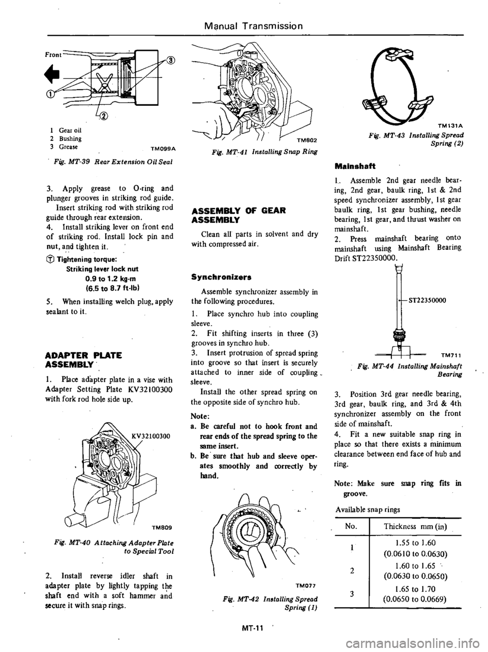
Front
if
r@
t
1
1
Gear
oil
2
Bushing
3
Grease
TM099A
Fig
MT
39
Rear
Extension
Oil
Seal
3
Apply
grease
to
D
ring
and
plunger
grooves
in
striking
rod
guide
Insert
striking
rod
with
striking
rod
guide
through
rear
extension
4
Install
striking
lever
on
front
end
of
striking
rod
Install
lock
pin
and
nut
and
tighten
it
fl
Tightening
torque
Striking
lever
lock
nut
0
9
to
1
2
kg
m
16
5
to
8
7
ft
Ib
5
When
installing
welch
plug
apply
sealant
to
it
ADAPTER
PLATE
ASSEMBLY
1
Place
adapter
plate
in
a
vise
with
Adaptet
Selling
Plate
KV32100300
with
fork
rod
hole
side
up
TMB09
Fig
MT
40
Attaching
Adapter
Phlte
to
Special
Tool
2
Install
reverse
idler
shaft
in
adapter
plate
by
lightly
tapping
the
shaft
end
with
a
soft
hammer
a
d
secure
it
with
snap
rings
Manual
Transmission
Fig
MT
4J
Installing
Snap
Ring
ASSEMBLY
OF
GEAR
ASSEMBLY
Clean
all
parts
in
solvent
and
dry
with
compressed
air
Synchronizers
Assemble
synchronizer
assembly
in
the
following
procedures
Place
synchro
hub
into
coupling
sleeve
2
Fit
shifting
inserts
in
three
3
grooves
in
synchro
hub
3
Insert
protrusion
of
spread
spring
into
groove
so
that
insert
is
securely
attached
to
inner
side
of
coupling
sleeve
Install
the
other
spread
spring
on
the
opposite
side
of
synchro
hub
Note
e
Be
careful
not
to
hook
front
and
rear
ends
of
the
spread
spring
to
the
same
insert
b
Be
sure
that
hub
and
sleeve
oper
ates
smoothly
and
correctly
by
hand
TM017
Fig
MT
42
Installing
Spread
Spring
MT
11
TM131A
Fig
MT
43
Installing
Spread
Spring
2
Mainshaft
Assemble
2nd
gear
needle
bear
ing
2nd
gear
baulk
ting
1
st
2nd
speed
synchronizer
assembly
I
st
gear
baulk
ring
1st
gear
bushing
needle
bearing
1st
gear
and
thrust
washer
on
mainshaft
2
Press
mainshaft
bearing
onto
mainshaft
using
Mainshaft
Bearing
Drift
ST22350000
H
ST22350000
TM711
Fig
MT
44
Installing
Mainshaft
Bearing
3
Position
3rd
gear
needle
bearing
3rd
gear
baulk
ring
and
3rd
4th
synchronizer
assembly
on
the
front
side
of
mainshaft
4
Fit
a
new
suitable
snap
ring
in
place
so
that
there
exists
a
minimum
clearance
between
end
face
of
hub
and
ring
Note
Make
sure
snap
ring
fits
in
groove
Available
snap
rings
No
Thickness
mm
in
1
55
to
1
60
0
0610
to
0
0630
1
60
to
1
65
0
0630
to
0
0650
1
65
to
I
70
0
0650
to
0
0669
1
2
3
Page 229 of 548
5
Fit
snap
ring
to
groove
in
rear
end
of
counter
gear
by
using
snap
ring
pliers
Note
Maire
sure
snap
ring
fits
in
groove
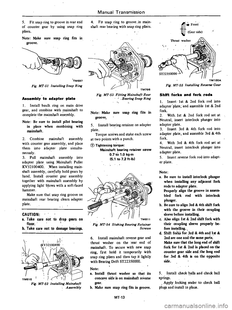
TM697
Fig
MT
5I
Imtalling
Snap
Ring
Assembly
to
adapter
plate
t
Install
baulk
ring
on
main
drive
gear
and
combine
with
mainshaft
to
complete
the
mainshaft
assembly
Note
Be
sure
to
install
pilot
bearing
in
place
when
combining
with
mainshaft
2
Combine
mainshaft
assembly
with
counter
gear
assembly
and
place
them
into
adapter
plate
simulta
neously
3
Pull
mainshaft
assembly
into
adapter
plate
using
Mainshaft
Puller
KV32
100400
When
installing
main
shaft
assembly
carefully
hold
gears
by
hand
Install
counter
gear
assembly
together
with
mainshaft
assembly
by
applying
light
blows
with
a
soft
faced
hammer
Make
sure
that
snap
ring
groove
on
mainshaft
rear
bearing
clears
adapter
plate
CAUTION
a
Take
care
not
to
drop
gears
on
floor
I
b
Take
care
not
to
damage
bearings
TM810
Fig
MT
52
1
Installing
Mainshaft
Assembly
Manual
Transmission
4
Fit
snap
ring
to
groove
in
main
shaft
rear
bearing
with
snap
ring
pliers
TM796
Fig
MT
53
Fitting
Mainshaft
Rear
Bearing
Snap
Ring
Note
Make
sure
snap
ring
fils
in
groove
5
Install
bearing
retainer
on
adapter
plate
Torque
screws
and
stake
each
screw
at
two
points
with
a
punch
fj
Tightening
torque
Mainshaft
bearing
retainer
saew
0
7
to
1
0
kg
m
15
1
to
7
2
ft
Ibl
TM811
Fig
MT
54
Staking
B
aring
Retain
r
Screw
6
Install
mainshaft
reverse
gear
and
thrust
washer
on
the
rear
end
of
mainshaft
To
secure
with
new
snap
ring
first
hold
it
temporarily
with
snap
ring
pliers
and
then
tap
it
lightly
with
Bearing
Drift
ST22350000
Note
a
Install
lhrust
washer
so
that
its
concave
side
is
on
mainshaet
reverse
gear
b
Make
sure
snap
ring
fits
in
groove
MT
13
J
r
Froni
Gear
side
TM100A
Fig
MT
55
Imtalling
R
Vf
e
Gear
Shift
forks
and
fork
rods
I
Insert
1st
2nd
fork
rod
into
adapter
plate
and
assemble
1st
2nd
fork
2
With
1st
2nd
fork
rod
set
at
Neutral
insert
interlock
plunger
into
adapter
plate
3
Insert
3rd
4th
fork
rod
into
adapter
plate
and
assemble
3rd
4th
fork
4
With
3rd
4th
fork
rod
set
at
Neutral
insert
interlock
plunger
into
adapter
plate
S
Insert
reverse
fork
rod
into
adapt
er
plate
Nole
a
Be
sure
to
install
interlock
plunger
when
installing
any
adjacent
fork
rods
to
adapter
plate
Properly
align
the
groove
in
assem
bled
fork
rod
with
interlock
plunger
b
Be
sure
to
align
3rd
4th
shift
fork
wilh
the
groove
in
their
coupling
sleeve
before
installing
c
Also
align
1st
2nd
shift
fork
with
their
coupling
sleeve
prop
dy
be
fore
inslalling
d
Shift
forks
for
3rd
4th
an
1st
2nd
are
one
and
the
same
parts
Make
sure
that
the
long
end
of
shift
fork
for
1st
2nd
is
placed
on
the
counter
gear
side
and
the
long
end
for
3rd
4th
is
on
the
opposite
side
5
Install
check
balls
and
check
ball
springs
Apply
locking
sealer
to
check
ball
plugs
and
install
in
place
Page 230 of 548
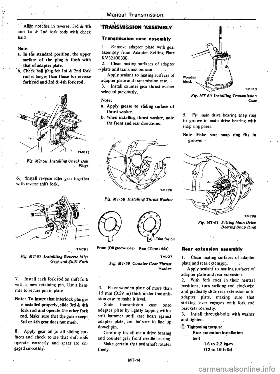
Align
notches
in
reverse
3rd
4th
and
1st
2nd
fork
rods
with
check
balls
Note
a
In
the
standard
position
the
upper
surface
of
the
ping
is
nush
with
thaI
of
adapter
plate
b
CheCk
balfpIug
for
i
st
2nd
fork
rod
is
longer
than
those
for
reverse
forkrod
and
3rd
4th
fork
rod
Manual
Transmission
TRANS
SSION
ASSEMBLY
Transmission
case
assembly
Remove
adapter
plale
with
gear
assembly
from
Adapter
Setting
Plate
KV32100300
2
Clean
mating
surfaces
of
adapter
plate
and
transmission
case
Apply
sealant
to
mating
surfaces
of
adapter
plate
3
nd
transmission
case
3
Install
counter
gear
thrust
washer
selected
previously
Note
a
Apply
grease
to
stiding
sorface
of
thrust
washer
b
When
installing
thrust
washer
note
the
front
and
rear
directions
Fig
MT
56
Installing
Check
Ball
0
Plugs
6
1nstall
rev
rse
idler
gear
together
with
reverse
shift
fork
TM791
Fig
MT
57
Installting
Re
ldler
Getg
and
Shift
Fork
7
Install
each
fork
rod
on
shift
fork
with
new
retainif
g
pin
U
a
ham
mer
toseCUfe
pin
in
place
Note
To
insure
that
interlock
plunger
is
installed
properly
slide
3rd
4th
fork
rod
and
operate
the
other
fork
rod
Make
sure
that
the
gear
except
lrd
or
4th
gear
does
not
mesh
8
Apply
g
ar
oil
o
all
sliding
sur
faces
and
check
to
see
that
shift
rods
operate
correctly
and
gears
are
en
gaged
smoothly
Fig
MT
58
Installing
Thrust
Washer
Front
Oil
groove
side
Rear
Thrust
side
TM727
Fig
MT
59
Counter
Gear
Thru
t
Washt
r
4
Place
wooden
plate
of
more
than
15
mm
0
59
in
thick
under
transmis
sion
case
to
make
it
level
Slide
transmission
case
onto
adapter
plate
by
lightly
tapping
with
a
soft
hammer
until
case
bears
against
adapter
plate
and
be
sure
to
line
up
dowel
pin
Carefully
install
main
drive
bearing
and
counter
gear
front
needle
bearing
Make
certain
that
rnainshaft
rotates
freely
MT14
1
Wooden
block
TM813
Fig
MT
60
Installing
Transmiuion
Cale
5
Fit
main
drive
bearing
snap
ring
to
groove
in
main
drive
bearing
with
snap
ring
pliers
Note
Make
sure
snap
ring
fits
in
groove
Fig
MT
61
Fitting
Main
Dri
Bearing
Snap
Ring
Rear
extension
assembly
Clean
mating
surfaces
of
adapter
p
Iat
aIld
rear
e
tens
i91
Apply
sealant
to
mating
surfaces
of
adapter
plate
and
rear
extension
2
With
fork
rods
in
their
neutral
positions
turn
striking
rod
clockwise
and
gradually
slide
rear
extension
onto
adapter
plate
making
sure
that
striking
lever
engages
with
fork
rod
brackets
correctly
3
Install
through
bolts
with
washer
and
tighten
b
Tightening
torque
Rear
extension
installation
bolt
1
6
to
2
2
kg
m
12
to
16
ft
lb
Page 231 of 548
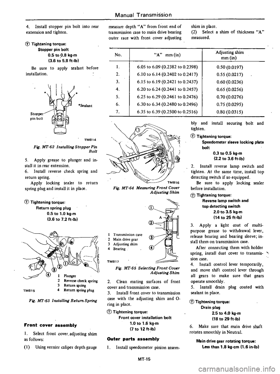
4
Install
stopper
pin
bolt
into
rear
extension
and
tighten
l
J
Tightening
torque
Stopper
pin
bolt
0
5
to
0
8
kg
m
3
6
to
5
8
ft
lb
Be
sure
to
apply
sealant
before
installation
Stopper
pin
bolt
Sealant
TM814
Fig
MT
62
Installing
Stopper
Pin
Bolt
5
Apply
grease
to
plunger
and
in
stall
it
in
rear
extension
6
Install
reverse
check
spring
and
return
spring
Apply
locking
sealer
to
return
spring
plug
and
install
it
in
place
l
J
Tightening
torque
Return
spring
plug
0
5
to
1
0
kg
m
3
6
to
7
2
ft
lb
TM815
Plunger
Reverse
check
spring
Return
spring
Return
spring
plug
Fig
MT
63
Installing
Return
Spring
Front
cover
assembly
1
Select
front
cover
adjusting
shim
as
follows
I
Using
vernier
caliper
depth
gauge
Manual
Transmission
measure
depth
A
from
front
end
of
transmission
case
to
main
drive
bearing
outer
race
with
front
cover
adjusting
No
A
mm
in
I
2
3
4
5
6
7
shim
in
place
2
Select
a
shim
of
thickness
A
measured
Adjusting
shim
mm
in
6
05
to
6
09
0
2382
to
0
2398
6
10
to
6
14
0
2402
to
0
2417
6
15
to
6
19
0
2421
to
0
2437
6
20
to
6
24
0
2441
to
0
2457
6
25
to
6
29
0
2461
to
0
2476
6
30
to
6
34
0
2480
to
0
2496
6
35
to
6
39
0
2500
to
0
2516
0
50
0
0197
0
55
0
0217
0
60
0
0236
0
65
0
0256
0
70
0
0276
0
75
0
0295
0
80
0
0315
TM816
Fig
MT
64
Meaauring
Front
Cover
Adjusting
Shim
CD
1
Transmission
case
2
Main
drive
gear
3
Adjusting
shim
4
Bearing
TM817
Fig
MT
65
Selecting
Front
Co
r
Adju
ting
Shim
2
Clean
mating
surfaces
of
front
cover
and
transmission
case
3
Install
front
cover
to
transmission
case
with
the
adjusting
shim
and
0
ring
in
place
l
J
Tightening
torque
Front
cover
installation
bolt
1
0
to
1
6
kg
m
7
to
12
ft
Ib
Outer
parts
assembly
Install
speedometer
pinion
assem
MT15
bly
and
install
securing
bolt
and
tighten
l
J
Tightening
torque
Speedometer
Ieeve
locking
plate
bolt
0
3
to
0
5
kg
m
2
2
to
3
6
ft
Ib
2
Install
reverse
lamp
switch
and
tighten
At
the
same
time
install
top
detecting
switch
if
so
equipped
Be
sure
to
apply
locking
sealer
before
installation
l
J
Tightening
torque
Revene
lamp
switch
and
top
detecting
switch
2
0
to
3
5
kg
m
14
to
25
ft
Ib
3
Apply
a
light
coat
of
multi
purpose
grease
to
withdrawal
lever
release
bearing
and
bearing
sleeve
in
stall
them
on
transmission
case
After
connecting
them
with
holder
spring
install
dust
cover
to
transmis
sian
case
4
Install
control
lever
temporarily
and
move
shift
control
lever
through
all
gears
to
make
sure
that
gears
operate
smoothly
5
Install
drain
plug
coated
with
sealant
in
place
l
J
Tightening
torque
Drain
plug
2
5
to
4
0
kg
m
18
to
29
ft
Ibl
6
Make
sure
that
main
drive
shaft
rotates
smoothly
in
Neutral
Main
drive
gear
rotating
torque
Les
than
1
8
kg
cm
1
6
in
Ibl
Page 232 of 548
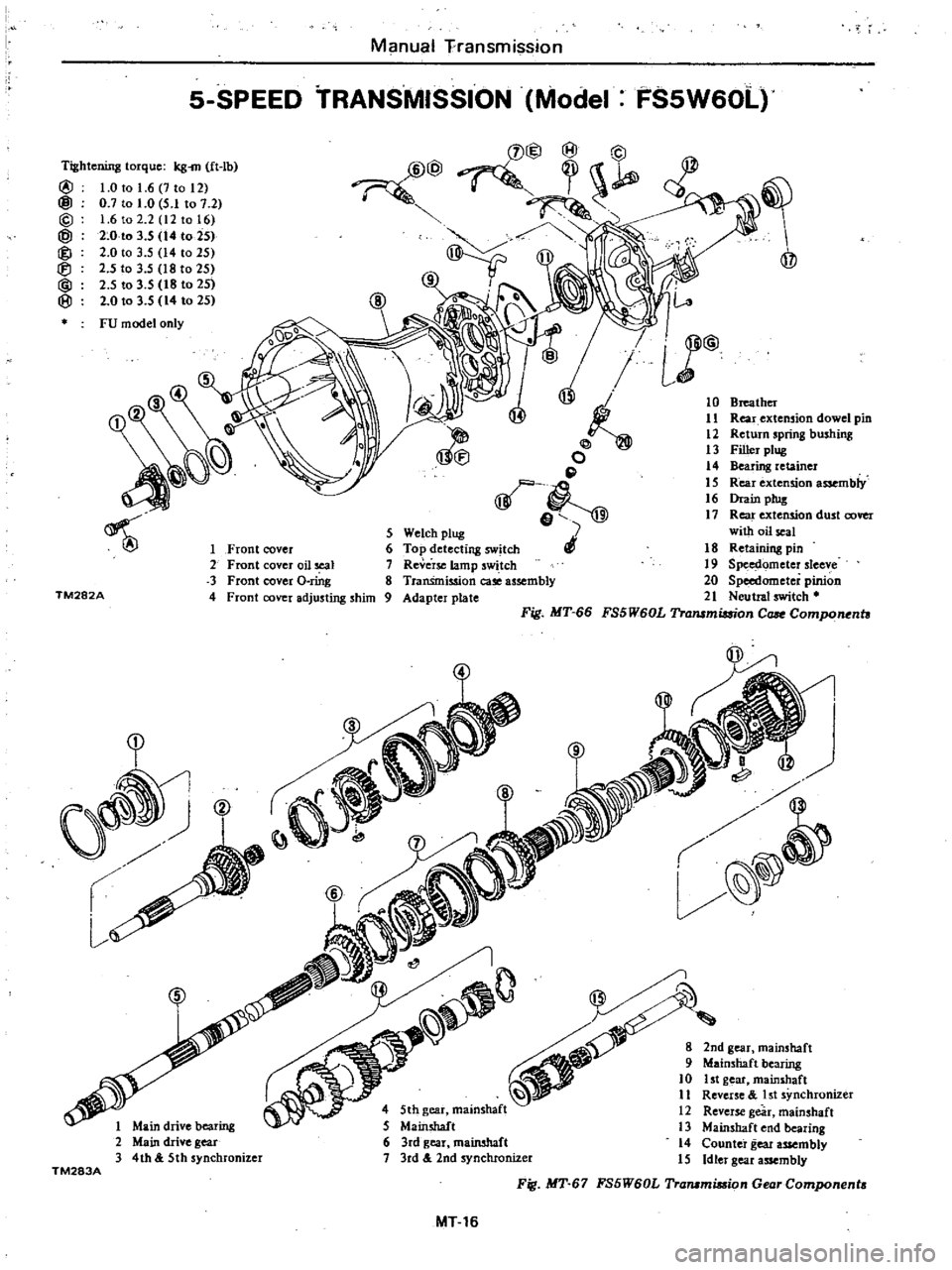
10
Breather
11
Rear
extension
dowel
pin
12
Retwn
spring
bushing
13
Filler
ptug
14
Bearing
retainer
15
Rear
extension
assembly
16
Drain
plug
17
Rear
extension
dust
cover
with
oil
seal
18
Retaining
pin
19
Spe
ometer
sleeve
20
Speedometer
pinion
21
Neutral
switch
FS5W60L
Tralllmimon
Case
Compo
nhl
Manual
Fransmission
S
SPEED
TRANSMISSION
Model
Tightening
torque
kg
m
ft
lb
@
1
0
to
1
6
7
to
12
@
0
7
to
1
0
5
1
to
7
2
@
1
6
to
2
2
12
to
16
@
2
0
to
3
5
14
to
25
@
2
0
to
3
5
14
to
25
2
5
to
3
5
18
to
25
@
2
5
to
3
5
18
to
25
i8J
2
0103
5
14
to
25
FU
model
only
7
@
o
p
e
5
Welch
ptug
6
Top
detecting
W
tch
7
Reve
rsc
lamp
swi
tch
8
TranSmission
case
assembly
9
Adapter
plate
5
TM282A
1
Front
cover
2
Front
cover
oil
seal
3
Front
cover
o
rfug
4
Front
cover
adjusting
shim
Fig
MT
66
l
Main
drive
bearing
Main
drive
gear
4th
5th
synchronizer
TM283A
MT
16
FSSW60L
Ll@
Page 233 of 548
Manual
Transmission
S
R
o
o
D
l
@
@
l
@
l
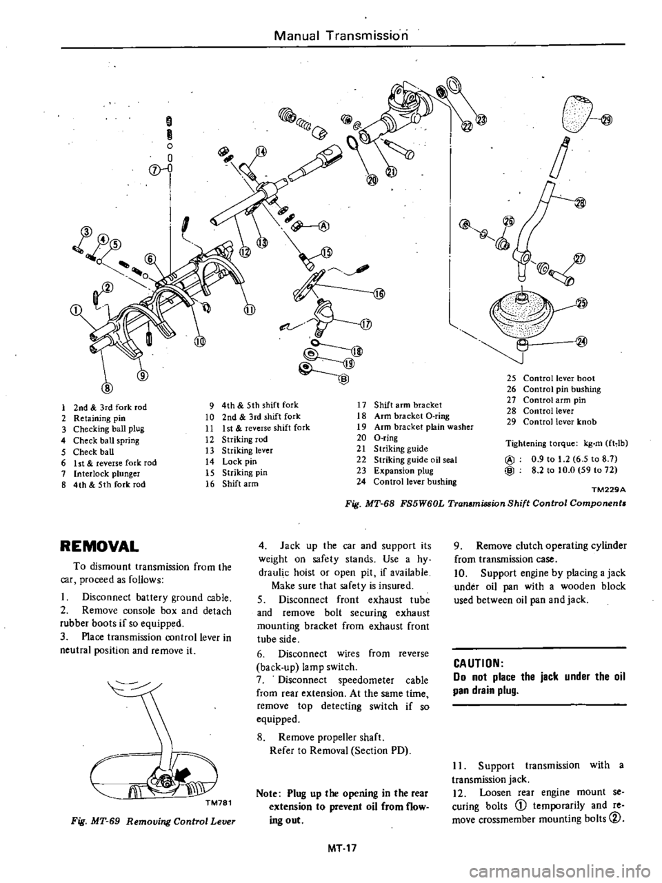
25
Control
lever
boot
26
Control
pin
bushing
27
Control
arm
pin
28
Control
lever
29
Control
lever
knob
1
2nd
3rd
fork
rod
9
4th
5th
shift
fork
17
Shift
arm
bracket
2
Retaining
pin
10
2nd
3rd
shift
fork
18
Arm
bracket
O
ring
3
Checking
ball
plug
11
Ist
reverse
shift
fork
19
Arm
bracket
plain
washer
4
Check
ball
spring
12
Striking
rod
20
O
ring
5
Check
ball
13
Striking
lever
21
S
lriking
guide
6
ht
reverse
fork
rod
14
Lock
pin
22
Striking
guide
oil
seal
7
Interlock
plunger
15
Striking
pin
23
Expansion
plug
8
4th
5th
fork
rod
16
Shift
arm
24
Control
lever
bushing
Tightening
torque
kg
m
fHb
@
0
9
to
1
2
6
5
to
8
7
@
8
2
to
to
O
59
to
72
TM229A
Fig
MT
68
FS5W60L
Transmission
Shift
Control
Components
REMOVAL
4
Jack
up
the
car
and
supporl
its
weight
on
safety
slands
Use
a
hy
draul
c
hoist
or
open
pit
if
available
Make
sure
that
safety
is
insured
S
Disconnect
front
exhaust
tube
and
remove
bolt
securing
exhaust
mounting
bracket
from
exhaust
front
tube
side
6
Disconnect
wires
from
reverse
back
up
lamp
switch
7
Disconnect
speedometer
cable
from
rear
extension
At
the
same
time
remove
top
detecting
switch
if
so
equipped
8
Remove
propeller
shaft
Refer
to
Removal
Section
PD
To
dismount
transmission
from
the
car
proceed
as
follows
Disconnect
battery
ground
cable
2
Remove
console
box
and
detach
rubber
boots
if
so
equipped
3
Place
transmission
control
lever
in
neutral
position
and
remove
it
CJi
J
TM781
Note
Plug
up
the
opening
in
the
rear
extension
to
prevent
oil
from
flow
ing
out
Fig
MT
69
Removing
Control
Lever
MT
17
9
Remove
clutch
operating
cylinder
from
transmission
case
10
Support
engine
by
placing
a
jack
under
oil
pan
with
a
wooden
block
used
between
oil
pan
and
jack
CAUTION
Do
not
place
the
jack
under
the
oil
pan
drain
plug
II
Support
transmission
with
a
transmission
jack
12
Loosen
rear
engine
mount
se
curing
bolts
CD
temporarily
and
re
move
crossmember
mounting
bolts
CV