diagram DATSUN 210 1979 Service Manual
[x] Cancel search | Manufacturer: DATSUN, Model Year: 1979, Model line: 210, Model: DATSUN 210 1979Pages: 548, PDF Size: 28.66 MB
Page 44 of 548
5
Fit
insert
ensuring
that
it
seats
on
bottom
face
of
its
recess
6
Newly
fitted
valve
seat
should
be
cut
or
ground
with
suitable
seat
cutter
or
grinding
stone
7
Apply
smalliunount
of
fine
grind
ing
compound
to
valve
contacting
face
and
put
valve
into
guide
Lap
valve
against
its
seat
ntil
proper
valve
seat
ing
is
obtained
Remove
valve
and
clean
valve
and
valve
seat
VALVE
ROCKER
ARM
1
AND
SHAFT
I
Check
rocker
arm
bore
and
shaft
for
scores
or
scuffs
2
Check
clearance
between
each
rocker
arm
and
shaft
by
measuring
inner
diameter
of
rocker
arm
bore
and
outer
diameter
of
shaft
If
either
clearance
is
not
within
spec
ification
replace
rocker
arm
and
or
shaft
3
Check
valve
end
contact
surface
of
rocker
arm
for
abnormal
wear
or
scuffs
VALVE
LIFTER
AND
PUSH
ROD
I
Check
valve
lifter
for
wear
or
scuffs
Check
bottom
end
of
valve
lifter
to
make
sure
it
has
a
slight
convex
Replace
valve
lifters
that
are
scored
worn
or
have
unsmooth
bot
tom
2
Check
clearance
between
lifter
hole
on
cylinder
block
and
valve
lifter
Replace
valve
lifter
if
clearance
ex
ceeds
wear
limit
3
Check
push
rod
for
bending
and
damage
Check
end
of
push
rod
for
rough
ness
or
excessive
wear
CAMSHAFT
AND
CAMSHAFT
BEARING
CAMSHAFT
BEARING
CLEARANCE
Journal
diameters
should
be
check
ed
with
a
micrometer
and
bearings
with
an
inside
dial
gauge
Measure
ments
should
then
be
compared
to
Engine
Mechanical
determine
whether
bearings
are
worn
If
worn
beyond
0
15
mm
0
0059
in
replace
using
Camshaft
Bearing
Drift
STl6Il0000
In
press
fitting
a
new
bearing
make
certain
that
oil
holes
in
block
and
bearing
are
properly
aligned
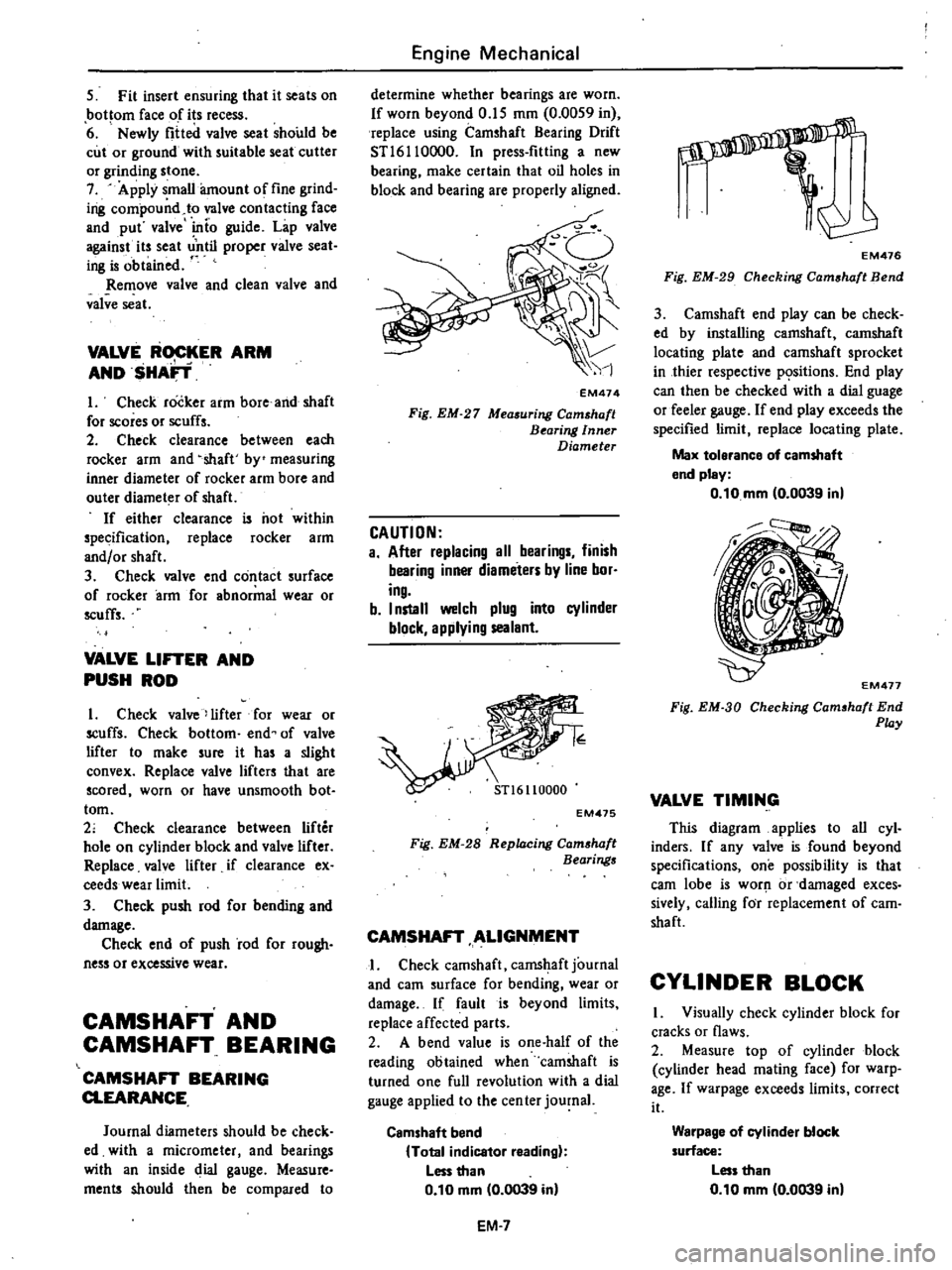
EM474
Fig
EM
27
Measuring
Camshaft
Bearing
Inner
Diameter
CAUTION
a
After
replacing
all
bearings
finish
bearing
inner
diameters
by
line
bor
ing
b
I
nstall
welch
plug
into
cylinder
block
applying
sealant
EM475
Fig
EM
28
Replacing
Cam
haft
Bearings
CAMSHAFT
ALIGNMENT
I
Check
camshaft
camshaft
journal
and
earn
surface
for
bending
wear
or
damage
If
fault
is
beyond
limits
replace
affected
parts
2
A
bend
value
is
one
half
of
the
reading
obtained
when
camshaft
is
turned
one
full
revolution
with
a
dial
gauge
applied
to
the
cen
ter
journal
Camshaft
bend
Total
indicator
reading
Less
than
0
10
mm
0
0039
in
EM
7
s
EM476
Fig
EM
29
Checking
Cam
haft
Bend
3
Camshaft
end
play
can
be
check
ed
by
installing
camshaft
camshaft
locating
plate
and
camshaft
sprocket
in
thier
respective
p
sitions
End
play
can
then
be
checked
with
a
dial
guage
or
feeler
gauge
If
end
play
exceeds
the
specified
limit
replace
locating
plate
Max
tolerance
of
camshaft
end
pley
0
10
mm
0
0039
in
EM477
Fig
EM
3D
Checking
Cam
haft
End
Play
VALVE
TIMING
This
diagram
applies
to
all
cyl
inders
If
any
valve
is
found
beyond
specifications
one
possibility
is
that
earn
lobe
is
worJ
1
or
damaged
exces
sively
calling
for
replacement
of
cam
shaft
CYLINDER
BLOCK
I
Visually
check
cylinder
block
for
cracks
or
flaws
2
Measure
top
of
cylinder
block
cylinder
head
mating
face
for
warp
age
If
warpage
exceeds
limits
correct
it
Warpage
of
cylinder
block
surface
Less
than
0
10
mm
0
0039
in
Page 104 of 548
1
Ignition
switch
2
Amplifier
3
Speed
switch
Note
a
Tightening
torque
is
1
8
to
2
2
kg
m
13
to
16
ft
Ib
b
After
replacement
start
engine
and
check
to
be
sure
that
fuel
is
not
leaking
and
that
anti
dieseling
sole
noid
i
in
good
condition
EFOSOA
Fig
EF47
Checking
Anti
dieaeling
Solenoid
l
SJ
Engine
Fuel
THROTTLE
OPENER
CONTROL
SYSTEM
When
idling
speed
is
too
high
and
does
not
drop
to
idling
speed
the
throttle
opener
control
system
should
be
checked
Manual
transmission
models
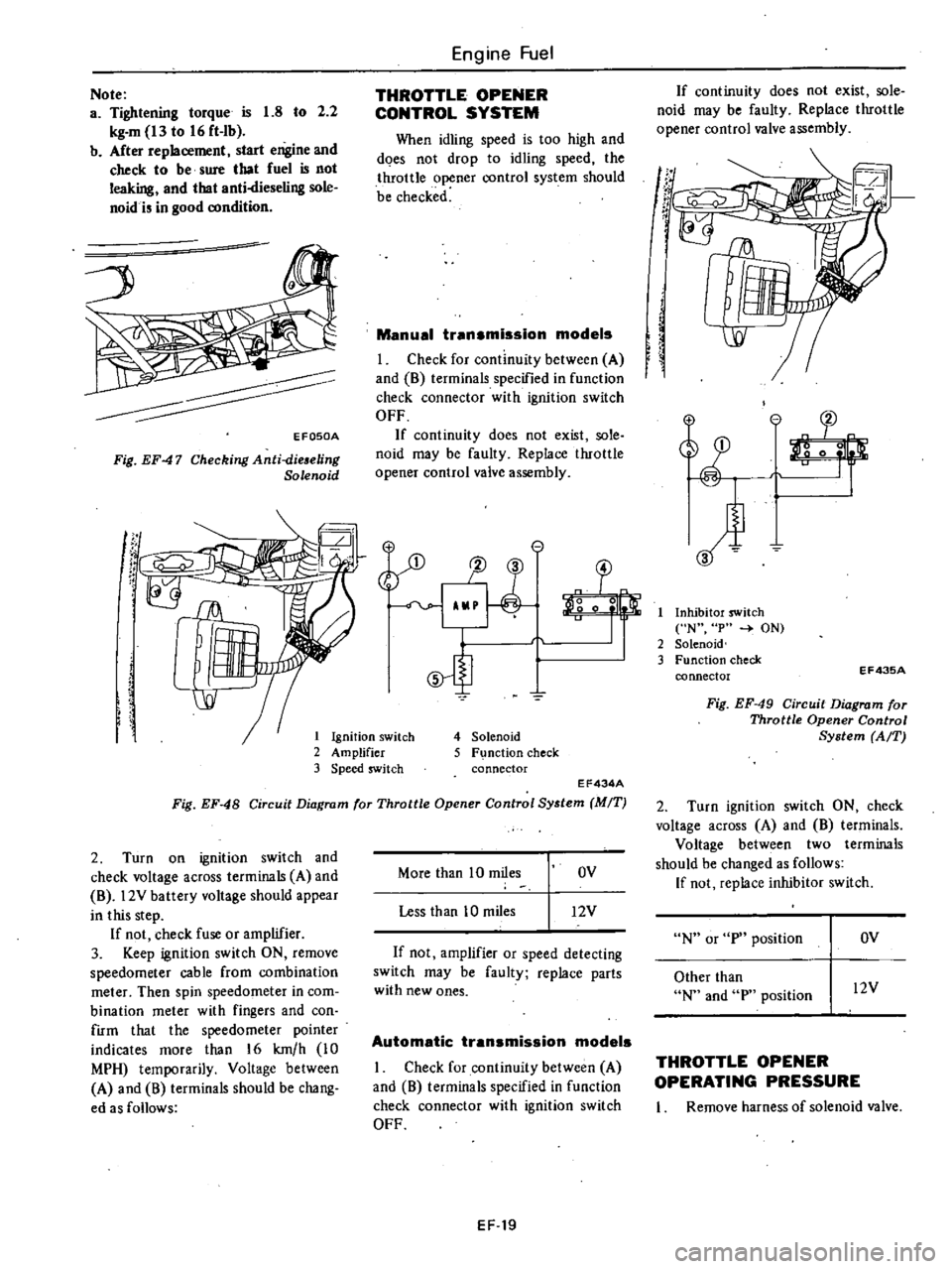
I
Check
for
continuity
between
A
and
8
terminals
specified
in
function
check
connector
with
ignition
switch
OFF
If
continuity
does
not
exist
sole
noid
may
be
faulty
Replace
throttle
opener
control
valve
assembly
e
1J
3
o
0
5
4
Solenoid
5
F
nction
check
connector
EF434A
Fig
EF
48
Circuit
Diagram
for
Throttle
Opener
Control
System
MIT
2
Turn
on
ignition
switch
and
check
voltage
across
terminals
A
and
8
l2V
battery
voltage
should
appear
in
this
step
If
not
check
fuse
or
amplifier
3
Keep
ignition
switch
ON
remove
speedometer
cable
from
combination
meter
Then
spin
speedometer
in
com
bination
meter
with
fingers
and
con
firm
that
the
speedometer
pointer
indicates
more
than
16
km
h
10
MPH
temporarily
Voltage
between
A
and
8
terminals
should
be
chang
ed
as
follows
More
than
10
miles
OV
Less
than
10
miles
12V
If
not
amplifier
or
speed
detecting
switch
may
be
faulty
replace
parts
with
new
ones
Automatic
transmission
models
I
Check
for
continuity
between
A
and
8
terminals
specified
in
function
check
connector
with
ignition
switch
OFF
EF
19
If
continuity
does
not
exist
sole
noid
may
be
faulty
Replace
throttle
opener
control
valve
assembly
If
t
r
If
I
Inhibitor
switch
N
p
ON
2
Solenoid
3
Function
check
connector
EF43SA
Fig
EF
49
Circuit
Diagram
for
Throttle
Opener
Control
System
AfT
2
Turn
ignition
switch
ON
check
voltage
across
A
and
8
terminals
Voltage
between
two
terminals
should
be
changed
as
follows
If
not
replace
inhibitor
switch
N
or
p
position
OV
Other
than
N
and
p
position
l2V
THROTTLE
OPENER
OPERATING
PRESSURE
I
Remove
harness
of
solenoid
valve
Page 178 of 548
DESCRIPTION
The
ignition
circuit
consists
of
igni
tion
switch
Ie
ignition
unit
dis
tributor
winng
ipark
plugs
and
battery
The
distributor
is
of
the
contactless
type
and
is
equipped
with
a
pick
up
coil
which
electrically
detects
the
igni
tion
timing
signal
in
place
of
the
ircuit
I
rea
r
of
the
conventional
distributor
The
IC
ignition
unit
is
a
new
addition
which
generates
the
signal
required
for
the
make
and
break
of
the
primary
current
for
the
ignition
coil
The
primary
current
is
supplied
by
the
battery
or
alternator
and
flows
through
the
primary
circuit
It
consists
of
the
ignition
switch
primary
winding
of
the
ignition
coil
IC
ignition
unit
and
all
connecting
low
tension
wiring
The
secondary
current
is
produced
by
the
ignition
coil
and
flows
through
the
secondary
circuit
resulting
in
high
voltage
spark
between
the
electrodes
of
the
spark
plugs
in
engine
cylinders
This
circuit
contains
the
secondary
winding
of
the
ignition
coil
distribu
tor
high
tension
cables
to
coil
and
spark
plugs
distributor
rotor
and
cap
When
the
ignition
switch
is
turned
on
and
the
distributor
reluctor
rotates
the
primary
current
flows
through
the
primary
winding
of
the
coil
and
through
IC
ignitionu
nit
to
ground
When
the
primary
circuit
is
opened
by
circuit
of
IC
ignition
unit
the
magnetic
field
built
up
in
the
primary
winding
of
the
coil
moves
through
the
secondary
winding
of
the
coil
in
ducing
high
voltage
This
high
voltage
is
produced
every
time
the
primary
circuit
opens
EngineElect
ical
System
IGNITfON
CIRCUIT
The
secondary
current
flows
through
the
high
tension
cable
to
the
distributor
cap
then
the
rotor
distributes
the
current
to
one
of
the
spark
plug
terminals
in
the
distrubutor
cap
Then
the
spark
occurs
while
the
secondary
current
jumps
the
gap
be
tween
the
insulated
electrode
and
the
ground
side
electrode
of
the
spark
plug
This
process
is
repeated
for
each
power
stroke
of
t
e
engine
The
spark
plug
should
be
inspected
cleaned
and
regapped
at
tune
up
Spark
plugs
should
also
be
replaced
periodically
as
specified
in
the
Maintenance
Schedule
The
remainder
of
the
ignition
component
parti
should
be
inspected
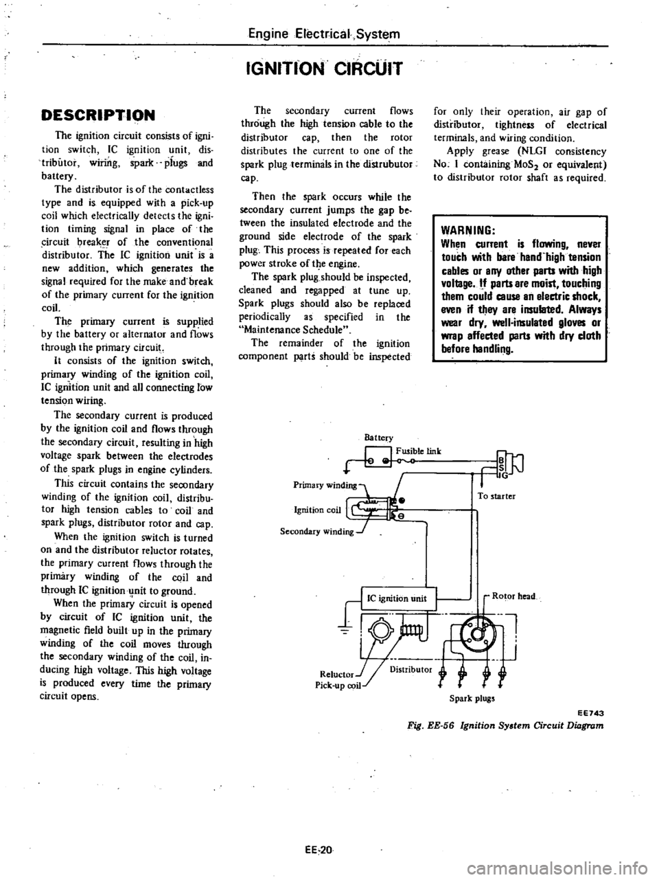
Battery
letink
Primary
winding
1
Ignition
coil
Secondary
winding
J
for
only
their
operation
air
gap
of
distributor
tightness
of
electrical
terminals
and
wiring
condition
Apply
grease
NLGI
consistency
No
I
containing
MaS
or
equivalent
to
distributor
rotor
shaft
as
required
WARNING
When
current
is
flowing
never
touch
with
bare
hand
high
tension
cables
or
any
other
parts
with
high
vollage
If
parts
are
moist
touching
them
could
cause
an
electric
shock
even
if
they
are
insulated
Always
wear
dry
well
insulated
gloves
or
wrap
affected
parts
with
dry
cloth
before
handling
To
starter
EE
20
Ro
or
head
Ul
J
r
Spark
plugs
EE743
Fig
EE
56
Ignition
System
Circuit
Diagram
Page 183 of 548
Engine
Electrical
System
Battery
Ignition
switch
CG
1
e
@
P
L
JO
L
J
Ignition
coil
r
Spark
timing
signal
I
oni
1oring
Clfcwt
0
R
Lock
Pi
k
il
preventing
c
up
co
circuit
Ln
n
Distributor
2P
fJ
1I
connector
8C
H
uty
control
ClICUlt
Power
switching
circuit
Current
limiting
circuit
Ie
ignition
unit
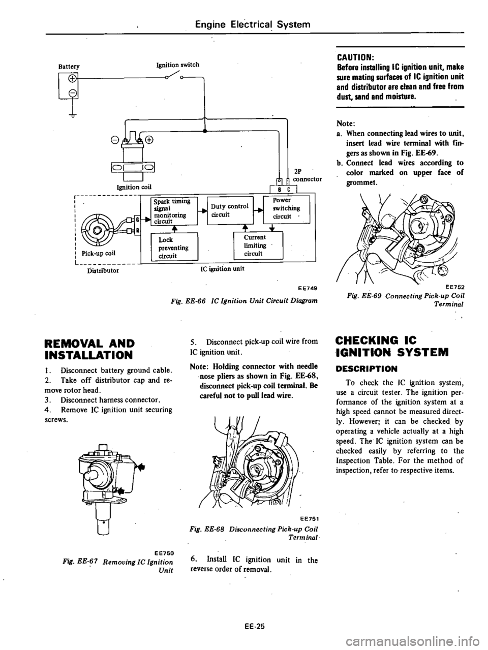
EE749
Fig
EE
66
Ie
Ignition
Unit
Circuit
Diagram
REMOVAL
AND
INSTALLATION
5
Disconnect
pick
up
coil
wire
from
IC
ignition
unit
Note
Holding
connector
with
needle
nose
pliers
as
shown
in
Fig
EE
68
disconnect
pick
up
coil
terminal
Be
careful
not
to
pull
lead
wire
I
Disconnect
battery
ground
cable
2
Take
off
distributor
cap
and
re
move
rotor
head
3
Disconnect
harness
connector
4
Remove
Ie
ignition
unit
securing
screws
rf
I
I
EE751
Fig
EE
68
Di
Connecting
Pick
up
Coil
Term
inal
eE750
Fig
EE
67
Removing
Ie
Ignition
Unit
6
InstaU
IC
ignition
unit
in
the
reverse
order
of
removal
EE
25
CAUTION
Before
instelling
IC
ignition
unit
mike
sure
mlting
surfaces
of
IC
ignition
unit
end
distributor
Ire
cleen
and
free
from
dust
sand
and
moisture
Note
a
When
connecting
lead
wires
to
unit
insert
lead
wire
terminal
with
fin
ger
as
shown
in
Fig
EE
69
b
Connect
lead
wires
according
to
color
marked
on
upper
face
of
grommet
EE752
Fig
EE
69
Connecting
Pick
up
Coil
Terminal
CHECKING
IC
IGNITION
SYSTEM
DESCRIPTION
To
check
the
IC
ignition
system
use
a
circuit
tester
The
ignition
per
fannance
of
the
ignition
system
at
a
high
speed
cannot
be
measured
direct
ly
However
it
can
be
checked
by
operating
a
vehicle
actually
at
a
high
speed
The
IC
ignition
system
can
be
checked
easily
by
referring
to
the
Inspection
Table
For
the
method
of
inspection
refer
to
respective
items
Page 259 of 548

P
r
n
P
rk
Torqu
con
r1lr
011
cool
Drain
volv
r
Front
lubricatic
Ora
1
x
j
L
u
2
6
CD
pr
u
II
ator
Automatic
Transmission
Lawand
b
r
kr
Brah
bond
f
12@
J
f
di
X
Ivacuum
r
11
throttl
Throttl
lenOI
I
I
yo
lv
e
f
k
UP
j
o
n
1
I
s
I
j
I
c
u
u
00
0
I
1
2
@
r
13
@2nd
3rdShlft
10
lv
In
Jl
Si
R
or
clutch
x
Otific
chick
volv
Throttl
drain
01
x
II
5
I
J
1
11
II
2
@l
2
dl
r
Shift
u
I
I
j2
II
Xu
J
I
f1
11
U
2
n
Ol
l
I
I
X
X
Secondary
Primary
90
rn01
101
90
nor
01
Not
Mark
d
X
ore
drain
lint
pru
r
Go
nor
f
d
p
u
ur
Govtrnor
prusu
r
r
cl
Torqu
convert
p
ur
TI
I
ratt
prUlur
AT455
Fig
A
T
B
Oil
Pre
re
Circuit
Diagram
P
rang
Par
AT7
Page 261 of 548
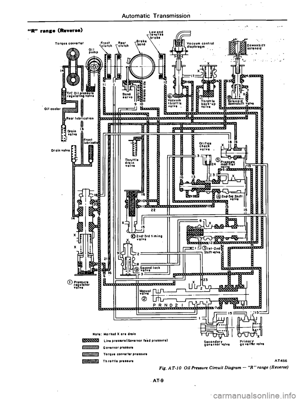
Automatic
Transmission
R
ren
e
Rever
Torque
con
r1
ril
j
j
I
f
I
12
C
I
J
111
x
J
0
8
Q
I
II
lr
Vacuum
Throttl
I
old
I
10
J
f
k
JP
L
u
I
lJ
El
J
U
I
II
O
co
l
chell
01
TO
I
drain
fol
il
Xl
tJj
1
J
l
2nd
3rd
Ii
minQ
x
U1
1
21
1
1C
ll
IIF
li@S
OC
II
to
0
r
6
9r3
Q
rm
g
L
1
u
iii
uLrt
23
r
t
@
PRND2
I
I
x
moo
la
OlenOid
Oil
cooler
1Rear
lubr
c
otion
f
L
ohl
r
Front
u
J
I
@2nd
3
Shift
vol
a
IS
I
12
u
l
r
I
3
w
q
r
4
I
l
Secondory
Qo
rnar
01
Primarf
Qo
i1lr
lol
Note
Mork
d
X
Qr
droin
j
Lin
prUltfrt
Go
nor
tced
r
rr
uur
J
G
0
1
1
101
pr
L
J
3
J
Torqu
can
tar
P
Urt
Tn
rotU
pr
ur
AT456
Fig
AT
10
Oil
Pr
lSure
Circuit
Diagram
R
range
Reverse
AT
9
Page 263 of 548
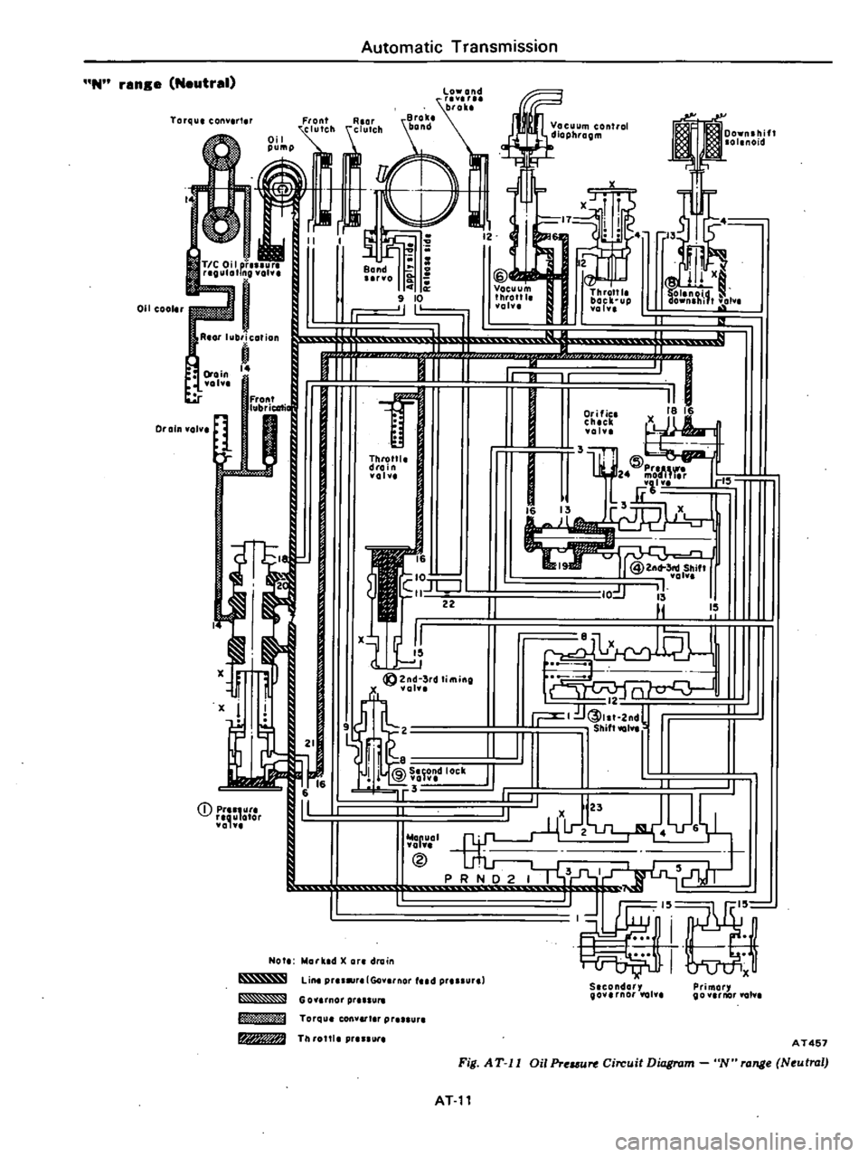
N
ran
e
Neutral
Torqu
conv
rt
r
011
cool
r
TIC
Oil
pillut
i
RlOr
lubricofion
j
l
oin
vo
Drain
volv
Fron
lub
icati
lJ
x
I
U
2
CD
pr
utl
II
o
or
Automatic
Transmission
e
m
eoo
h
m
Band
ii
@
rvo
Vacuum
Thronl
0
throttl
boclt
up
I
I
olu
Yolv
I
r
Throttl
drain
volv
16
IO
S
X
tJ1
1
g
2nd
3rd
timing
oh
8
r
t
@
I
Not
hlorll
td
X
or
drain
Lin
pru
lr
lGo
rnor
d
pr
ur
60
rnol
pr
m
Torqu
convert
r
Plu
ur
W
TI
I
rottl
p
nur
f
r
1
1
18
I
L
O
lie
chick
volv
3lIf
IDpre
l
h
J
24
m
iM
llv
16
3
X
1X
0
jr
i
II
I
II
I
I
I
X
U4lJ
I
3
J
a
i
I
U1J
S
condory
governor
lal
Primor
gov
rnor
tO
AT457
Fig
AT
II
Oil
Pr
u
Circuit
Diagram
N
rang
Neutral
ATll
Page 269 of 548
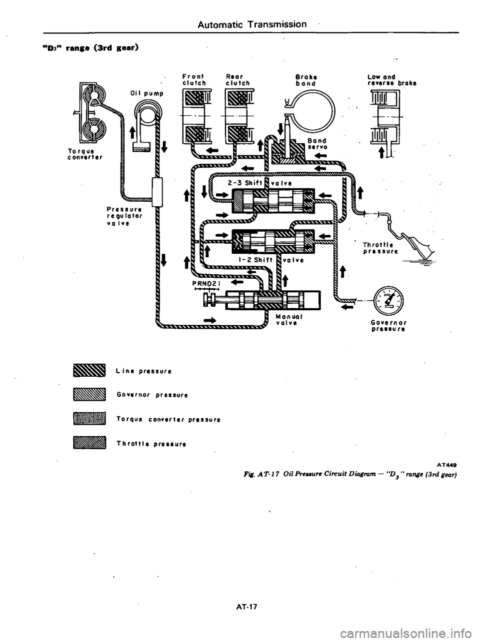
D3
ran
3rd
g
ar
Oi
I
pump
1
t
Torque
J
C
onYlrt
r
I
i
t
t
Pressure
reQula
or
Ya
lye
L
i
ns
pressure
Goyernor
pressure
Automatic
Transmission
Front
clurch
Rlar
clutch
Brake
bond
Low
and
rever
brake
0
thBond
L
B
so
J
1
1
1
lt
r
T
tr
Throttle
pressure
t
t
I
@
t
Governor
pr
au
r
Torque
canYlr
er
pr
ssure
rIA
Throttle
pressure
AT449
Fill
AT
17
Oil
Pro
ure
Circuit
Diagram
D3
range
3rd
gear
AT
17
Page 271 of 548

Automatic
Transmission
D
nnse
klckdown
Shift
valvas
In
2nd
sear
position
Vacuum
control
dlophroem
r
r
X
I
i
jI
2
dl
2
l
s
o
@
i
i
JJ
1
1
I
N1
1
JJ
r
OI
r
J
@
I
J
ju
n
II
r
1
o
N
m
II
lln
pru
r
Gov
nor
Iud
pr
ssurel
1
x
x
S
condary
Primor
90V
nor
val
00
rnor
olv
Low
ond
brok
Brak
bond
2
Oil
cooler
I
r
J
80nd
no
C
a
i
0
J
P
N
R
ar
lubrication
aJ
8
ll
Ill
f
I
f
j
l
l
0
1
1
Throttl
drain
voh
i
Xl
U
II
CD
r
lIU
afor
volv
I
l
r
Go
rnor
pr
IU
Torqu
conv
t
r
pr
lur
TIl
rotll
p
lure
AT458
Fig
AT
18
Oil
Pr
mn
Circuit
Diagram
D
rong
kickdown
hift
va
v
s
in
2nd
gear
position
AT
19
X
Throttl
back
up
vain
F
w
I
P
b
I
1
Orific
18
16
ch
ck
X
val
1
r
@2n
3n
lShift
01
l
l
I
Page 273 of 548

2
renge
2nd
Beer
Oil
cool
Reor
lubrication
o
4
Drain
oha
Fron
lubricaf
Drain
vol
x
x
I
Ii
6
II
D
r
ou
alar
01
1
4
Automatic
Transmission
J
R
or
j
j
I
r
r
Bond
0
0
41
9
10
Throttl
I
r
lc
uP
a
II
J
I
i
ll
fr
t
rr
1
1
I
i
Throttle
I
drain
ahe
j
01
1816
x
@Zn6
3rd
Shift
101
1
J
is
t1
1x
J
I
I
n
s
t
Z
l
n
S
II
I
1
1
1
II
IS
N
U
g
2nd
3rd
timing
X
vol
I
I
2
S
j
000j
Ul
I1
I
w
X
fo4anuol
P
R
lIo
Not
Morked
X
art
drain
Slcondory
govunor
ViII
Primor
go
nor
vol
line
pr
ur
Go
nor
lid
pr
ure
G
o
rnOI
pr
Torqul
con
r
p
JUri
Th
rotU
p
AT459
Fig
AT
19
Oil
ProIlU
Circuit
Diagram
2
range
2nd
tar
AT
21