high DATSUN 210 1979 Service Manual
[x] Cancel search | Manufacturer: DATSUN, Model Year: 1979, Model line: 210, Model: DATSUN 210 1979Pages: 548, PDF Size: 28.66 MB
Page 13 of 548
General
Information
LIFTING
POINTS
AND
TOWING
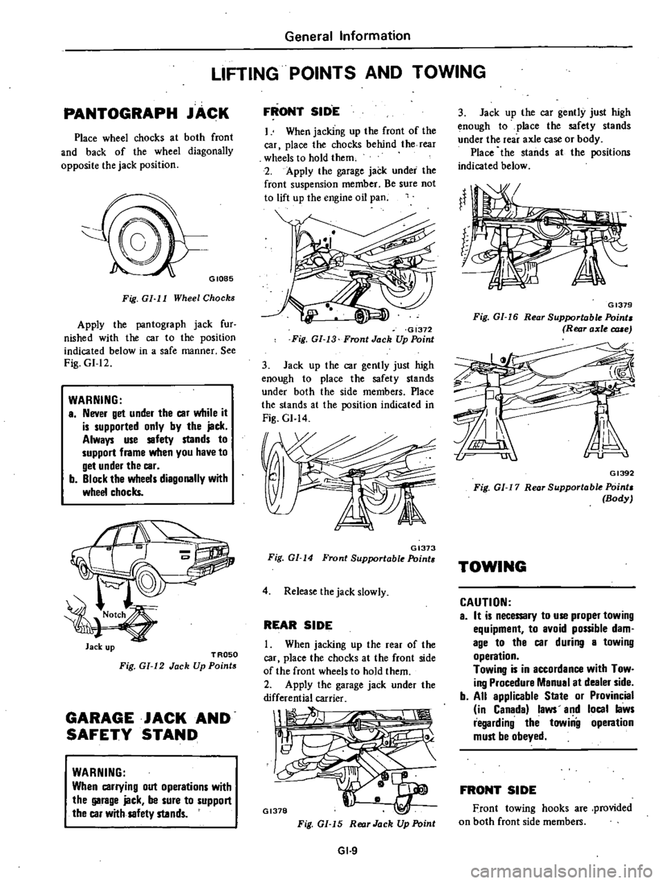
PANTOGRAPH
JACK
Place
wheel
chocks
at
both
front
and
back
of
the
wheel
diagonally
opposite
the
jack
position
GIOB5
Fig
GI
I
I
Wheel
Chocks
Apply
the
pantograph
jack
fur
nished
with
the
car
to
the
position
indicated
below
in
a
safe
manner
See
Fig
GI
12
WARNING
a
Never
get
under
the
car
while
it
is
supported
only
by
the
jack
Always
use
safety
stands
to
support
frame
when
you
have
to
get
under
the
car
b
Block
the
wheels
diagonally
with
wheel
chocks
Jack
up
TROSO
Fig
GI
12
Jack
Up
Points
GARAGE
JACK
AND
SAFETY
STAND
WARNING
When
carrying
out
operations
with
the
garage
jack
be
sure
to
support
the
car
with
safety
stands
FRONT
SID
E
I
When
jacking
up
the
front
of
the
car
place
the
chocks
behind
the
rear
wheels
to
hold
them
2
Apply
the
garage
jack
under
the
front
suspension
member
Be
sure
not
to
lift
up
the
engine
oil
pan
GI372
Fig
GI
13
Front
Jack
Up
Point
3
Jack
up
the
car
gently
just
high
enough
to
place
the
safety
stands
under
both
the
side
members
Place
the
stands
at
the
position
indicated
in
Fig
GI
14
GI373
Fig
GI
14
Front
Supportable
Point
4
Release
the
jack
slowly
REAR
SIDE
When
jacking
up
the
rear
of
the
car
place
the
chocks
at
the
front
side
of
the
front
wheels
to
hold
them
2
Apply
the
garage
jack
under
the
differential
carrier
1
1
Il
GI378
Fig
GI
15
Rear
Jack
Up
Point
GI
9
3
Jack
up
the
car
gently
just
high
enough
to
place
the
safety
stands
under
the
rear
axle
case
or
body
Place
the
stands
at
the
positions
indicated
below
GI379
Fig
GI
16
Rear
Supportable
Point
Rear
axle
c
rue
GI392
Fig
01
17
Rear
Supportable
Point
Body
TOWING
CAUTION
a
It
is
necemry
to
use
proper
towing
equipment
to
avoid
possible
dam
age
to
the
car
during
a
towing
operation
Towing
is
in
accordance
with
Tow
ing
Procedure
Manual
at
dealer
side
b
All
applicable
State
or
Provincial
in
Canada
laws
and
local
laws
regarding
the
towiilg
operation
must
be
obeyed
FRONT
SIDE
Front
towing
hooks
are
provided
on
both
front
side
members
Page 18 of 548
pl
ice
mter
as
an
assembly
2
When
installing
oil
mter
tighten
by
hand
Note
Do
not
overtighten
oil
filter
lest
leakage
shoUld
occur
CHANGING
ENGINE
COOLANT
PERMANENT
ANTI
FREEZE
COOLANT
Note
The
permanent
anti
freeze
coolant
is
an
ethylene
glya
l
base
product
containing
chemical
in
hibitors
to
protect
the
cooling
system
from
rusting
and
corrosion
The
anti
freeze
does
not
cOntain
any
glycerine
or
ethyl
alcohol
It
will
not
evaporate
or
boil
a
ay
and
can
be
ilsed
with
either
high
or
low
temperature
thermostats
It
flows
freely
transfers
heat
efficiently
and
will
not
clog
the
passages
in
the
cooling
system
The
anti
freeze
must
not
be
mixed
with
other
product
This
coolant
can
be
used
throughout
the
seasons
of
the
year
Whenever
coolant
is
changed
the
cooling
system
must
be
flushed
and
refilled
with
a
new
coolant
Check
the
coolant
level
See
instructions
attached
to
the
anti
freeze
container
for
mixing
ratio
of
anti
freeze
to
water
CHECKING
COOLING
SYSTEM
HOSES
AND
CONNECTIONS
Check
hoses
and
fittings
for
loose
connections
or
deterioration
Re
tighten
or
replace
if
necessary
INSPECTION
OF
RADIATOR
CAP
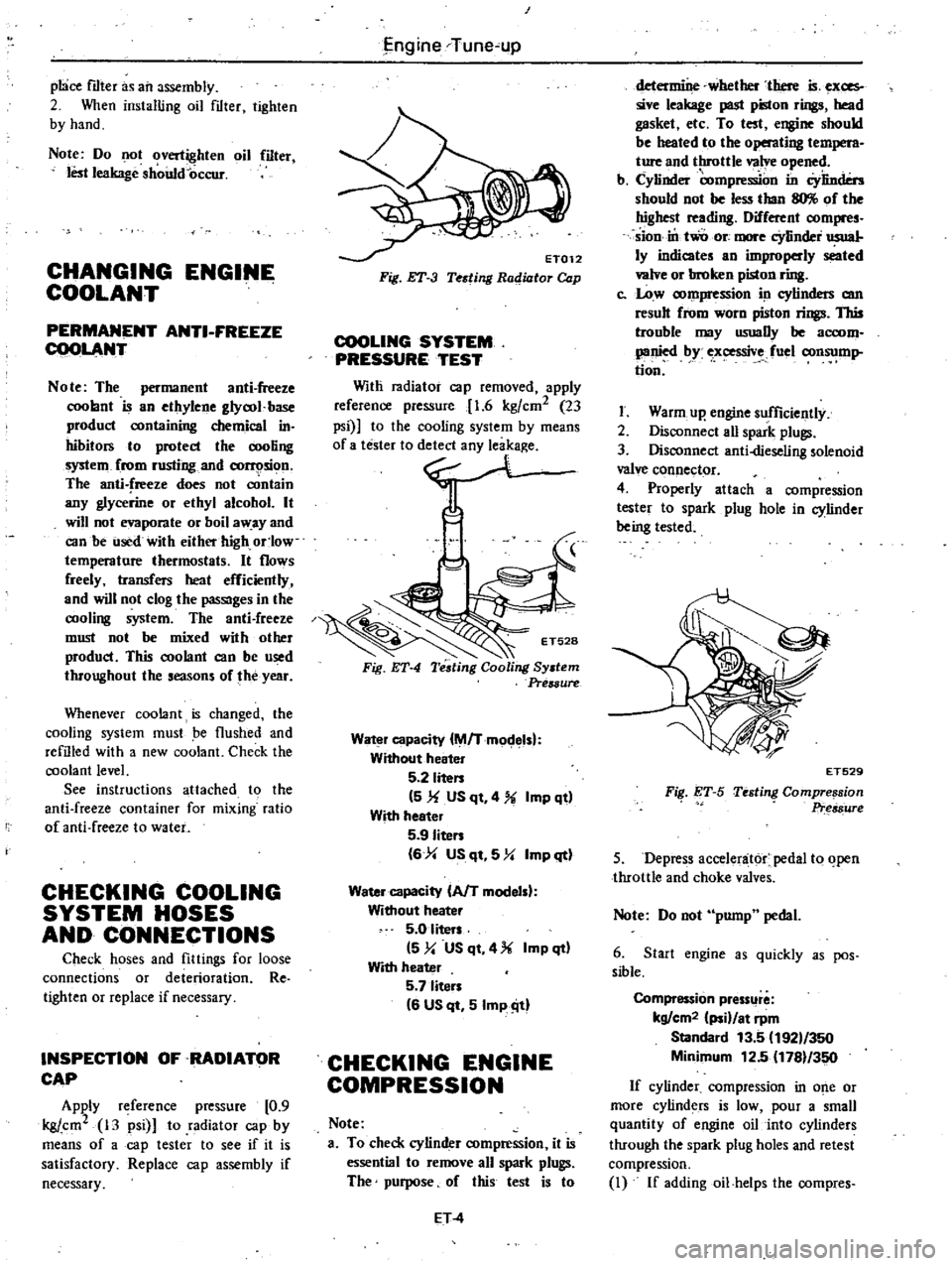
Apply
reference
pressure
0
9
kgj
cm2
13
psi
to
radiator
cap
by
means
of
a
cap
tester
to
see
if
it
is
satisfactory
Replace
cap
assembly
if
necessary
I
j
ngine
Tune
up
ET012
Fig
ET
3
Testing
Radiator
Cap
COOLING
SYSTEM
PRESSURE
TEST
Witli
radiator
cap
removed
apply
reference
pressure
1
6
kgfcm2
23
psi
to
the
cooling
system
by
means
0
no
Fig
ET
4
Water
capacity
M
Tmodelsl
Without
heater
5
2
liten
5
1f
US
qt
4
Imp
qt
With
heeter
5
9
Iiten
6
4
US
qt
5
Y
Imp
qt
Water
capacity
AfT
modelsl
Without
heater
5
0
liters
5
y
US
qt
4
Imp
qt
With
heater
5
7
liten
6
US
qt
5
Imp
ill
CHECKING
ENGINE
COMPRESSION
Note
a
To
check
cylinder
compression
it
is
essential
to
remove
all
spark
plugs
The
purpose
of
this
test
is
to
ET
4
determine
whether
there
is
exces
sive
leakage
past
piston
rings
head
gasket
etc
To
test
engine
should
be
heated
to
the
operating
t
M
ture
and
throttle
valve
opened
b
Cylinder
compre
on
in
Cylinders
should
not
be
less
than
llO
of
the
highest
reading
Different
compres
sion
in
two
ore
more
cYlinder
usual
ly
indicates
an
improperly
seated
valve
or
broken
piston
ring
c
Low
compression
in
cylinders
am
result
from
worn
piston
rings
This
trouble
may
usuaDy
be
accom
panied
by
ex
ssive
fuel
consump
tion
I
Warm
up
engine
sufficiently
2
Disconnect
aU
spark
plugs
3
Disconnect
anti
dieseling
solenoid
valve
connector
4
Properly
attach
a
compression
tester
to
spark
plug
hole
in
cylinder
being
tested
FiI
ET
S
ET529
Testing
Compre
sion
Pr
s8ure
5
Depress
accelenit6r
pedal
to
open
throttle
and
choke
valves
Note
Do
not
pump
pedal
6
Start
engine
as
quickly
as
pos
sible
Compression
pressllre
kg
cm2
ii
at
rpm
Standard
13
5
192
350
Minimum
12
5
1781
350
If
cylinder
compression
in
o
e
or
more
cylinders
is
low
pour
a
small
quantity
of
engine
oil
into
cylinders
through
the
spark
plug
holes
and
retest
compression
I
If
addingoil
helps
the
compres
Page 20 of 548
SO
B
T
D
C
l650
rpm
Non
California
models
except
Canada
100
B
T
D
C
650
rpm
Canada
models
Note
On
FU
models
ignition
timing
is
set
under
a
condition
where
distributor
vacuum
hose
is
discon
nected
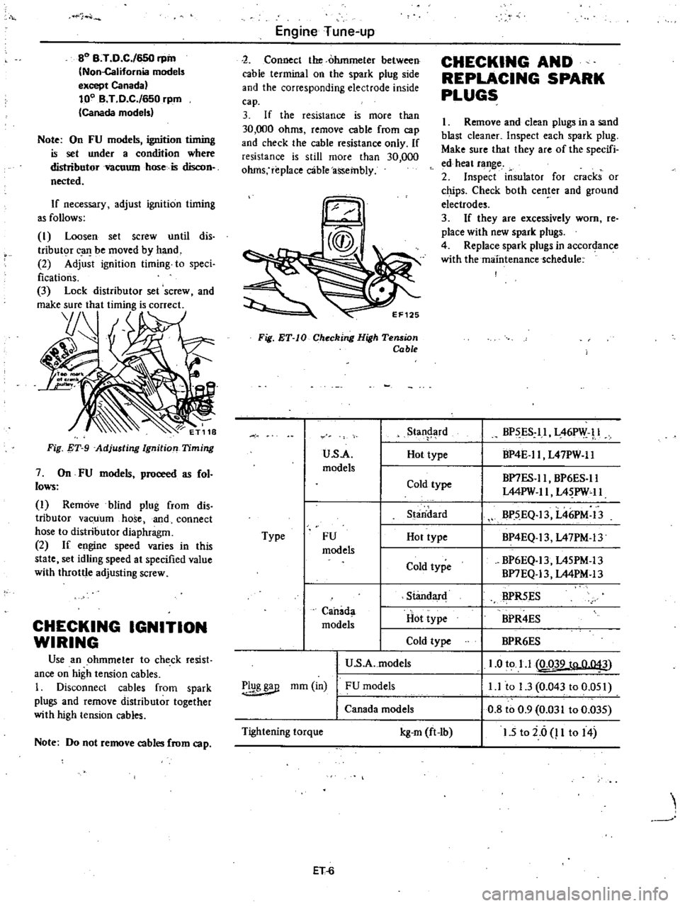
If
necessary
adjust
ignition
timing
as
follows
I
Loosen
set
screw
until
dis
tributor
c
uJ
be
moved
by
hand
2
Adjust
ignition
timing
to
speci
fications
3
Lock
distributor
set
screw
and
make
sure
that
timing
is
correct
YJ
Fig
T
9
Adjusting
Ignition
Timing
7
On
FU
models
proceed
as
fol
lows
I
Remove
blind
plug
from
dis
tributor
vacuum
hose
and
connect
hose
to
distributor
diaphragm
2
If
engine
speed
varies
in
this
state
set
idling
speed
at
specified
value
with
throttle
adjusting
screw
CHECKING
IGNITION
WIRING
Use
an
ohmmeter
to
check
resist
ance
on
high
tension
cables
1
Disconnect
cables
from
spark
plugs
and
remove
distributor
together
with
high
tension
cables
Note
Do
not
remove
cables
from
cap
Engine
Tune
up
2
Connect
the
ohmmeter
between
cable
terminal
on
the
spark
plug
side
and
the
corresponding
electrode
inside
cap
3
If
the
resistance
is
more
than
30
000
ohms
remove
cable
from
cap
and
check
the
cable
resistance
only
If
resistance
is
still
more
than
30
000
ohms
replace
c3ble
assembly
Fig
ET
IO
Checking
High
Tension
Cable
u
s
A
models
Type
FU
models
Standard
Hot
type
Cold
type
U
S
A
models
Canada
models
r
1g
mm
in
FU
models
Canada
models
Tightening
torque
kg
m
ft
lb
ET
6
Stan
rd
Hot
type
Cold
type
S
aridard
Hot
type
Cold
type
CHECKING
AND
REPLACING
SPARK
PLUGS
I
Remove
and
clean
plugs
in
a
sand
blast
cleaner
Inspect
each
spark
plug
Make
sure
that
they
are
of
the
specifi
ed
heat
range
2
Inspect
insulator
for
cracks
or
chips
Check
both
center
and
ground
electrodes
3
If
they
are
excessively
worn
re
place
with
new
spark
plugs
4
Replace
spark
plugs
in
accordance
with
the
maintenance
schedule
BP
ES
ll
L46PW
l
BP4E
ll
L47PW
ll
BP7ES
ll
BP6ES
ll
L44PW
II
L4
PW
11
BP5
EQ
13
L46PM
13
BP4EQ
13
L47PM
13
BP6EQ
13
L45PM
13
BP7EQ
13
L44PM
13
BPR5ES
BPR4ES
BPR6ES
1
0
to
1
1
LQ39
to
0
043
l
l
to
1
3
0
043
to
0
051
0
8
to
0
9
0
031
to
0
035
1
5
to
i
6
P
to
14
Page 29 of 548
IBnition
and
fuel
system
Ignition
timing
Manual
transmission
models
Automatic
transmission
models
in
D
position
1
Spark
plug
Gap
U
s
A
models
Canada
models
FU
models
High
tension
cable
resistance
CO
percentage
at
idling
speed
No
air
Manual
transmission
models
Automatic
transmission
models
f
in
D
position
Evaporatlv
emission
control
system
Supplied
pressure
l
Pressure
variation
TIGHTENING
TORQUE
Valve
rocker
adjusting
nut
Spark
plug
Engine
Tune
up
degree
rpm
degree
rpm
mm
in
mm
in
mm
in
ohm
rpm
rpm
mmH29
inH20
mmH20
inHP
kg
m
ft
lb
kg
m
ft
lb
ET1S
SO
B
T
D
C
j700
rpm
California
FU
models
T
D
CJ700
i
m
r
Non
California
Canada
models
SO
B
T
D
C
j6S0
rpm
California
models
80
B
T
D
C
j6S0
rpm
Non
California
models
ex
cept
Canada
100
B
T
D
C
j6S0
rpm
Canada
models
1
0
to
l
l
0
039
to
0
043
0
8
to
0
9
0
031
to
0
035
LI
to
1
3
0
043
to
O
OSI
an
3O
OOO
2
r
1
700
2
r
1
6S0
400
IS
7S
less
than
2S
0
98
I
f
r
1
6
to
2
2
12
to
16
1
5
to
2
0
11
to
14
jf
0
Page 30 of 548
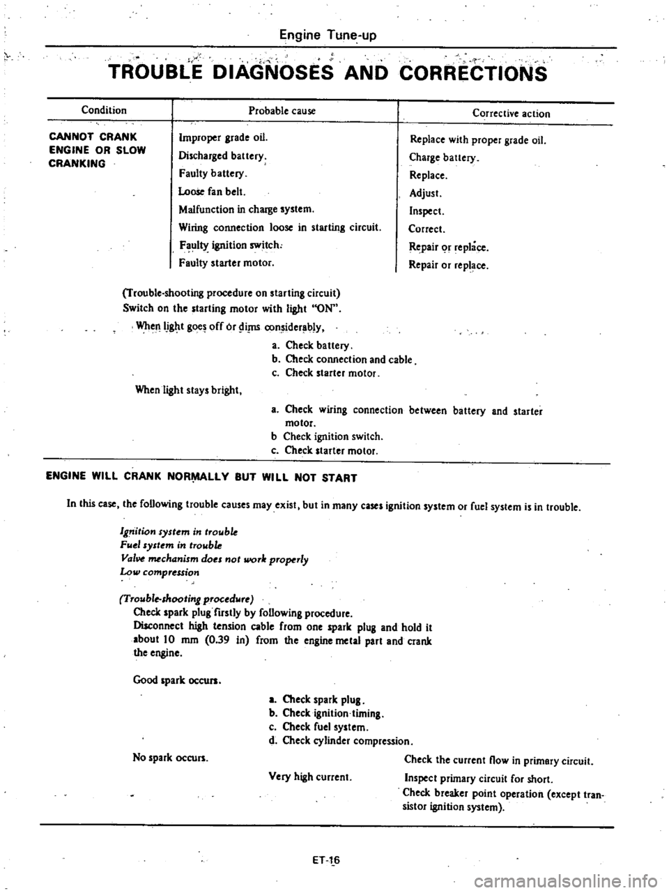
Engine
Tune
up
TROUBLE
DIAGNOSES
AND
CORRECTIONS
Condition
Probable
cause
CANNOT
CRANK
ENGINE
OR
SLOW
CRANKING
Improper
grade
oil
Discharged
battery
Faulty
battery
Loose
fan
belt
Malfunction
in
charge
system
Wiring
connection
loose
in
starting
circuit
F
ul1Y
ignition
switch
Faulty
starter
motor
Trouble
shooting
procedure
on
starting
circuit
Switch
on
the
starting
motor
with
light
ON
WheJlIJght
gOO
off
or
Ii
J1S
considerably
a
Check
battery
b
Check
connection
and
cable
c
Check
starter
motor
When
light
stays
bright
Corrective
action
Replace
with
proper
grade
oil
Charge
battery
Replace
Adjust
Inspect
Correct
Repair
or
replace
Repair
or
replace
a
Check
wlflng
connection
between
battery
and
starter
motor
b
Check
ignition
switch
c
Check
starter
motor
ENGINE
WILL
CRANK
NOR
LLY
BUT
WILL
NOT
START
In
this
case
the
following
trouble
causes
may
exist
but
in
many
cases
ignition
system
or
fuel
system
is
in
trouble
19
ition
syst
m
in
trouble
FII
1
system
in
trowb
Val
mechanism
do
not
work
properly
Low
compression
Trouble
shooting
procedure
Check
spark
plug
firstly
by
following
procedure
Disconnect
high
tension
cable
from
one
spark
plug
and
hold
it
about
10
mm
0
39
in
from
the
engine
metal
part
and
crank
the
engine
Good
spark
occurs
a
Check
spark
plug
b
Checkignition
timing
c
Check
fuel
system
d
Check
cylinder
compression
Check
the
current
now
in
primary
circuit
Very
high
current
Inspect
primary
circuit
for
short
Check
breaker
point
operation
except
tran
sistor
ignition
system
No
spark
occurs
ET
l
6
Page 31 of 548
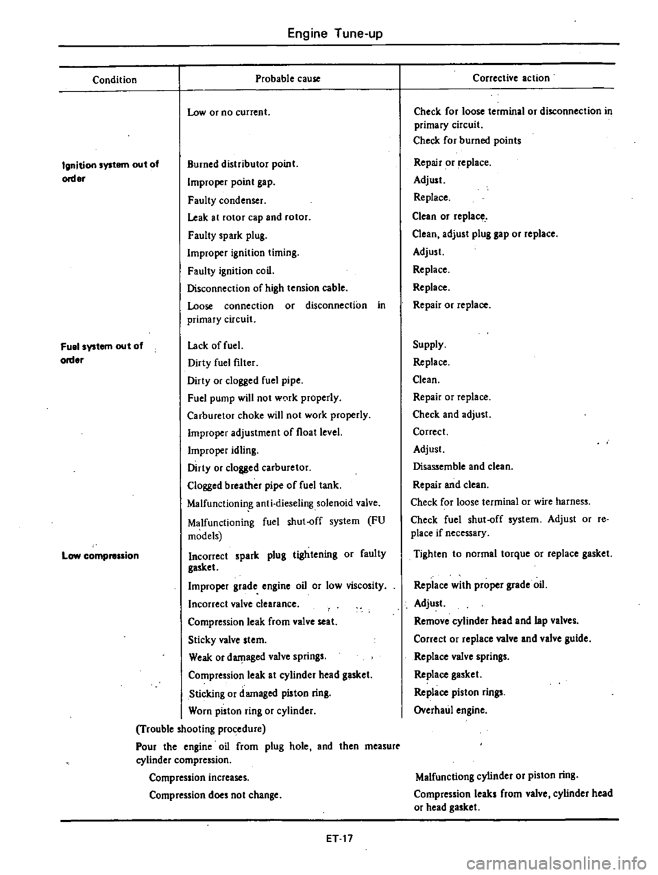
Engine
Tune
up
Condition
Probable
cause
Low
or
no
current
Ignition
system
out
of
order
Burned
distributor
point
Improper
point
gap
Faulty
condenser
Leak
at
rotor
cap
and
rotor
Faulty
spark
plug
Improper
ignition
timing
Faulty
ignition
coil
Disconnecrion
of
high
tension
cable
Loose
connection
or
disconnection
in
primary
circuit
Lack
offuel
Dirty
fuel
filter
Dirty
or
clogged
fuel
pipe
Fuel
pump
will
not
w0rk
properly
Carburetor
choke
will
not
work
properly
Improper
adjustment
of
float
level
Improper
idling
Dirty
or
clogged
carburetor
Clogged
breather
pipe
of
fuel
tank
Malfunctionin
g
anti
dieseling
solenoid
valve
Malfunctioning
fuel
shut
off
system
FU
models
Incorrect
spark
plug
tightening
or
faulty
gasket
Improper
grade
engine
oil
or
low
viscosity
Incorrect
valve
clearance
Compression
leak
from
valve
seat
Sticky
valve
stem
Weak
or
damaged
valve
springs
Compression
leak
at
cylinder
head
gasket
Sticking
or
damaged
piston
ring
Worn
piston
ring
or
cylinder
Trouble
looting
procedure
Pour
the
engine
oil
from
plug
hole
and
then
measurt
cylinder
compression
Fuel
system
out
of
order
Low
compression
Compression
increases
Compression
does
not
change
ET
17
Corrective
action
Check
for
loose
terminal
or
disconnection
in
primary
circuit
Check
for
burned
points
Repair
or
replace
Adjust
Replace
Clean
or
replace
Clean
adjust
plug
gap
or
replace
Adjust
Replace
Replace
Repair
or
replace
Supply
Replace
Clean
Repair
or
replace
Check
and
adjust
Correct
Adjust
Disassemble
and
clean
Repair
and
clean
Check
for
loose
terminal
or
wire
harness
Check
fuel
shut
off
system
Adjust
or
re
place
if
necessary
Tighten
to
normal
torque
or
replace
gasket
Replace
with
proper
grade
oil
Adjust
Remove
cylinder
head
and
lap
valves
Correct
or
replace
valve
and
valve
guide
Replace
valve
springs
Replace
gasket
Replace
piston
rings
Overhaul
engine
Malfunctiong
cylinder
or
piston
ring
Compression
leaks
from
valve
cylinder
head
or
head
gasket
Page 32 of 548
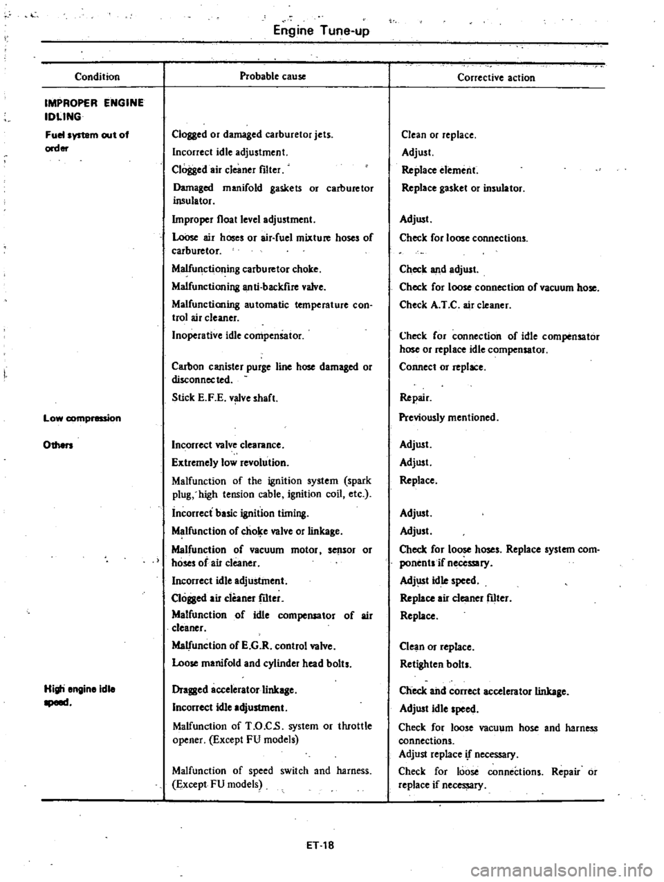
Condition
IMPROPER
ENGINE
IDLING
Fuelsystam
out
of
order
Low
1
ion
Engine
Tune
up
Probable
cause
Clogged
or
damaged
carburetor
jets
Incorrect
idle
adjustment
Clogged
air
cleaner
filter
Damaged
manifold
gaskets
or
carburetor
insulator
bnproper
float
level
adjustment
LoOse
air
hoses
or
air
fuel
mixture
hoses
of
carburetor
Malfunctioning
carburetor
choke
Malfunctioning
anti
backfire
valve
Malfunctioning
automatic
temperature
con
trol
air
cleaner
Inoperative
idle
compensator
Carbon
canister
purge
line
hose
damaged
or
disconnected
Stick
E
F
E
v
ve
shaft
Othen
Incorrect
valve
clearance
Extremely
low
revolution
Malfunction
of
the
ignition
system
spark
plug
high
tension
cable
ignition
coil
etc
incorrect
basic
ignition
timing
Malfunction
of
chol
e
valve
or
linkage
Malfunction
of
vacuum
motor
sensor
or
hoses
of
air
cleaner
Incorrect
idle
adjustment
Cloged
air
cleaner
fIIter
Malfunction
of
idle
compensator
of
air
cleaner
Malfunction
of
E
G
R
control
valve
Loose
manifold
and
cylinder
head
bolts
Higli
engine
idle
opem
Dragged
accelerator
linkage
Incorrect
idle
adjustment
Malfunction
of
T
O
C
s
system
or
tluottle
opener
Except
FU
models
Malfunction
of
speed
switch
and
harness
Except
FU
models
ET
18
Corrective
action
Clean
or
replace
Adjust
Replace
element
Replace
gasket
or
insulator
Adjust
Check
for
loose
connections
Check
lUId
adjust
Check
for
loose
connection
of
vacuum
hose
Check
A
I
C
air
cleaner
Check
for
connection
of
idle
compensator
hose
or
replace
idle
compensator
Connect
or
replace
Repair
Previously
mentioned
Adjust
Adjust
Replace
Adjust
Adjust
Check
for
loose
hoses
Replace
system
com
ponentsif
necessary
Adj
lSt
idle
speed
Replace
air
cleaner
filter
Replace
Clean
or
replace
Retighten
bolts
Check
ahd
correct
accelerator
linkage
Adjust
idle
speed
Check
for
loose
vacuum
hose
and
harness
connections
Adjust
replace
if
necessary
Check
for
loose
connections
Repair
or
replace
if
necessary
Page 34 of 548
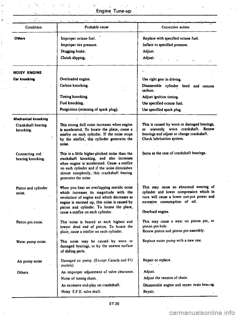
Condition
Othen
NOISY
ENGINE
Cor
knockillll
M8chanicol
knocking
Crankshaft
bearing
knocking
Connecting
rod
bearing
knocking
Piston
and
cylinder
noise
Piston
pin
noise
Water
pump
noise
Air
pump
noise
Others
Engine
Tune
up
Probable
cause
Improper
octane
fuel
Improper
tire
pressure
Dragging
brake
Dutch
slipping
Overloaded
engine
Carbon
knocking
Timing
knocking
Fuel
knocking
Preignition
miswing
of
spark
plug
This
strong
dull
noise
increases
when
engine
is
occelerated
To
locate
the
place
cause
a
misfire
on
each
cylinder
If
the
noise
stops
by
the
misfire
this
cylinder
generates
the
noise
This
is
a
little
higher
pitched
noise
than
the
crankshaft
knocking
and
also
increases
when
engine
is
accelerated
Cause
a
misfire
on
each
cylinder
and
if
the
noise
diminishes
almost
completely
this
crankshaft
bearing
generates
the
noise
When
you
hear
an
overlapping
metalic
noise
which
increases
its
magnitude
with
the
revolution
of
engine
and
which
decreases
as
engil
e
is
warmed
up
this
noise
is
caused
by
piston
and
cylinder
To
locate
the
place
cause
a
misfire
on
each
cylinder
This
noise
is
heared
at
each
highest
and
lowest
dead
end
of
piston
To
locate
the
place
cause
a
misfire
on
each
cylinder
This
noise
may
be
caused
by
worn
or
damaged
b
arings
or
by
the
uneven
surface
of
sliding
parts
Damaged
air
pump
Except
Canada
and
FU
models
An
improper
adjustment
of
valve
clearance
Noise
of
timing
chain
An
excessive
end
play
on
crankshaft
Noisy
E
F
E
valve
shaft
H20
Corrective
action
Replace
with
specified
octane
fuel
Inflate
to
sptcifled
pressure
Adjust
Adjwt
Use
right
gear
in
driving
Disassemble
cylinder
head
and
remove
carbon
Adjust
ignition
timing
Use
specified
octane
fuel
Use
specified
spark
plug
This
is
caused
by
worn
or
damaged
bearings
or
unevenly
worn
crankshaft
Renew
bearings
and
adjust
or
change
crankshaft
Check
lubrication
system
Same
as
the
case
of
crankshaft
bearings
This
may
cause
an
abnormal
wearing
of
cylinder
and
lower
compression
which
in
turn
will
cause
a
lower
out
put
power
and
excess
ive
consumption
of
oil
Overhaul
engine
This
may
cause
a
wear
on
piston
pin
or
piston
pin
hole
Renew
piston
and
piston
pin
assembly
Replace
water
pump
with
a
new
one
Repair
or
replace
Adjust
Adjust
the
tension
of
chain
Disassemble
engine
and
new
main
beaung
Repair
Page 37 of 548
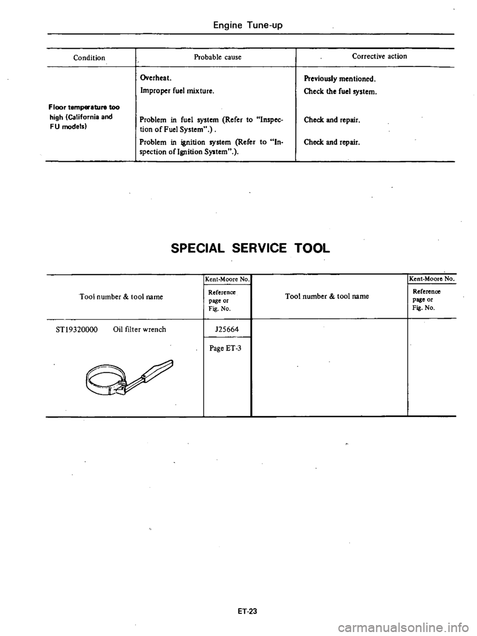
Engine
Tune
up
Condition
Probable
cause
Overheat
Improper
fuel
mixture
Floor
temp
ture
too
high
California
and
FU
model
Problem
in
fuel
system
Refer
to
Inspec
tion
of
Fuel
System
Problem
in
ignition
system
Refer
to
In
spection
oflgnition
System
Corrective
action
Previously
mentioned
Check
the
fuel
system
Check
and
repair
Check
and
repair
SPECIAL
SERVICE
TOOL
Kent
Moore
No
Tool
number
tool
name
Reference
page
or
Fig
No
STl9320000
Oil
filter
wrench
125664
Page
ET
3
ET
23
Kent
Moore
No
Tool
number
tool
name
Reference
page
or
Fig
No
Page 40 of 548
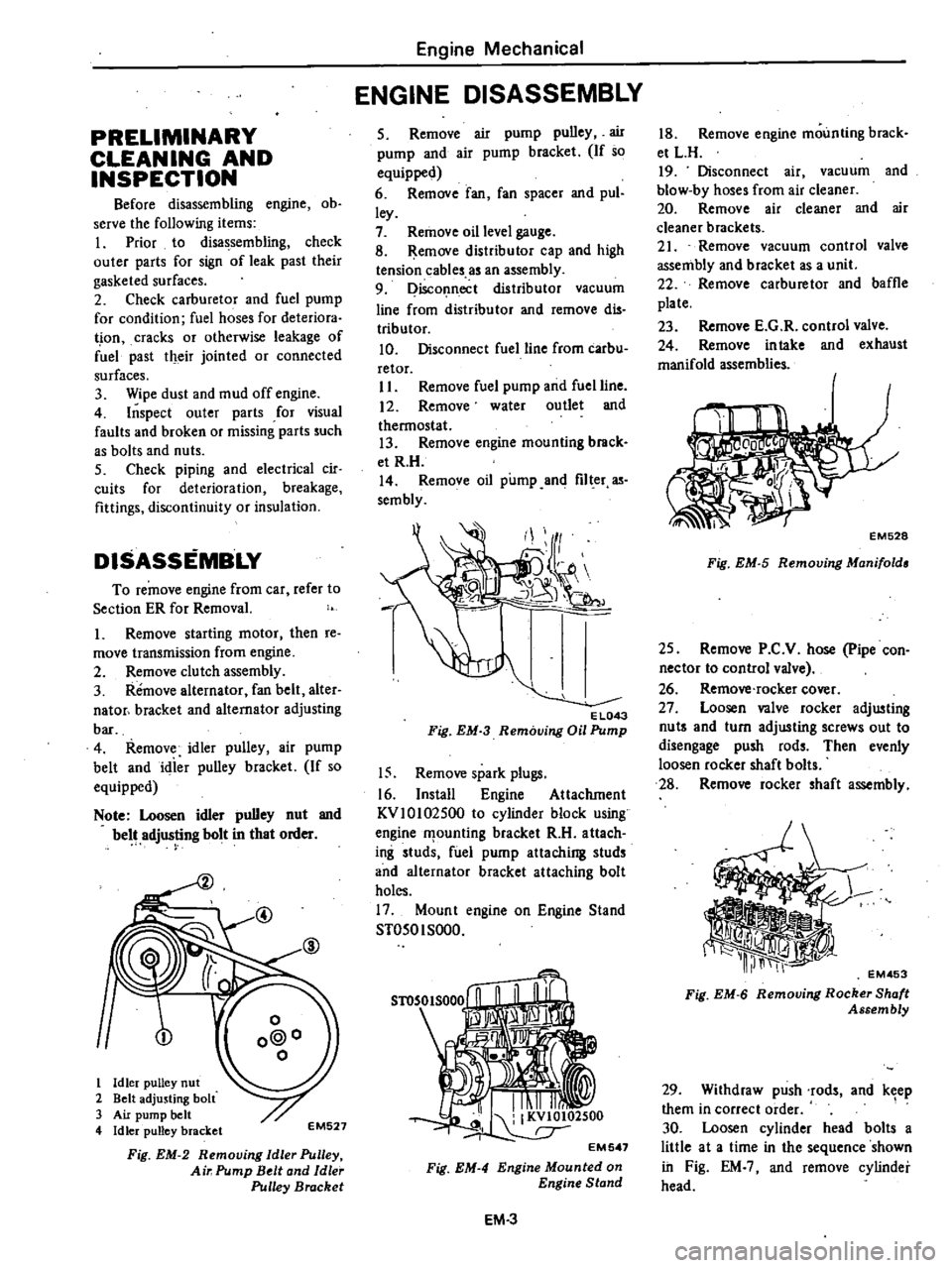
PRELIMINARY
CLEANING
AND
INSPECTION
Before
disassembling
engine
ob
serve
the
following
items
I
Prior
to
disassembling
check
outer
parts
for
sign
of
leak
past
their
gasketed
surfaces
2
Check
carburetor
and
fuel
pump
for
condition
fuel
hoses
for
deteriora
t
ion
cracks
or
otherwise
leakage
of
fuel
past
their
jointed
or
connected
surfaces
3
Wipe
dust
and
mud
off
engine
4
Inspect
outer
parts
for
visual
faults
and
broken
or
missing
parts
such
as
bolts
and
nuts
5
Check
piping
and
electrical
cir
cuits
for
deterioration
breakage
fittings
discontinuity
or
insulation
DISASSEMBLY
To
remove
engine
from
car
refer
to
Section
ER
for
Removal
1
Remove
starting
motor
then
re
move
transmission
from
engine
2
Remove
clutch
assembly
3
Remove
alternator
fan
belt
alter
nator
bracket
and
alternator
adjusting
bar
4
Remove
idler
pulley
air
pump
belt
and
idier
pulley
bracket
If
so
equipped
Note
Loosen
idler
pulley
nut
and
belt
adjusting
bolt
in
that
order
@
1
Idler
pulley
nut
2
Belt
adjusting
bolt
3
Air
pump
belt
4
Idler
pulley
bracket
EM527
Fig
EM
2
Removing
Idle
Pulley
Air
Pump
Belt
and
Idle
Pulley
Bracket
Engine
Mechanical
ENGINE
DISASSEMBLY
5
Remove
air
pump
pulley
air
pump
and
air
pump
bracket
If
so
equipped
6
Remove
fan
fan
spacer
and
pul
ley
7
Remove
oil
level
gauge
8
Remove
distributor
cap
and
high
tension
cables
as
an
assembly
9
Disconnect
distributor
vacuum
line
from
distributor
and
remove
dis
tributor
10
Disconnect
fuel
line
from
carbu
retor
II
Remove
fuel
pump
and
fuel
line
12
Remove
water
outlet
and
thermostat
13
Remove
engine
mounting
brack
et
R
H
14
Remove
oil
pump
and
filter
as
sembly
EL043
Fig
EM
3
Removing
Oil
Pump
15
Remove
spark
plugs
16
Install
Engine
Attachment
KVlOI02500
to
cylinder
block
using
engine
f1
ounling
bracket
R
H
attach
ing
studs
fuel
pump
attaching
studs
and
alternator
bracket
attaching
bolt
holes
17
Mount
engine
on
Engine
Stand
ST050I
SOOO
Fig
EM
4
EM
3
18
Remove
engine
mounting
brack
et
L
H
19
Disconnect
air
vacuum
and
blow
by
hoses
from
air
cleaner
20
Remove
air
cleaner
and
air
cleaner
brackets
21
Remove
vacuum
control
valve
assembly
and
bracket
as
a
unit
22
Remove
carburetor
and
baffle
plate
23
Remove
E
G
R
control
valve
24
Remove
intake
and
exhaust
manifold
assemblies
EM528
Fig
EM
5
Removing
Manifold
25
Remove
P
C
V
hose
pipe
con
nector
to
control
valve
26
Remove
rocker
cover
27
Loosen
valve
rocker
adjusting
nut
and
turn
adjusting
screws
out
to
disengage
push
rods
Then
evenly
loosen
rocker
shaft
bolts
28
Remove
rocker
shaft
assembly
EM453
Fig
EM
6
Removing
Rocker
Shaft
Assembly
29
Withdraw
push
rods
and
keep
them
in
correct
order
1
30
Loosen
cylinder
head
bolts
a
little
at
a
time
in
the
sequence
shown
in
Fig
EM
and
remove
cylinder
head