DATSUN B110 1969 Service Owner's Guide
Manufacturer: DATSUN, Model Year: 1969, Model line: B110, Model: DATSUN B110 1969Pages: 136, PDF Size: 5.64 MB
Page 31 of 136
BDgiDe
TIghtening
torque
40
to
43
ft
Ib
Install
the
push
rod
Install
the
rocker
haft
assembly
and
tighten
the
I
ocker
haft
bracket
bolts
to
the
specIfied
torque
Tightening
torque
15
to
18
ft
lb
Note
TIghtening
operation
should
be
made
gradually
10
separating
two
or
three
stages
and
outwardly
from
the
center
bracket
In
tall
the
Intake
and
exhaust
mamfolds
TIghtening
torque
65
to
10
ft
lb
AdJu
t
valve
clemance
wIth
the
specIfied
dlmenblOn
Install
the
rocker
cover
and
carburetor
assem
bly
I
n
tdll
the
watel
pump
and
thermostat
Tlghtemng
tOl
que
65
to
10
ft
lb
I
nstall
the
crankshaft
pulley
Tighten
the
crank
pulley
bolt
to
the
specIfied
torque
TIghtenIng
torque
109
to
116
ft
lb
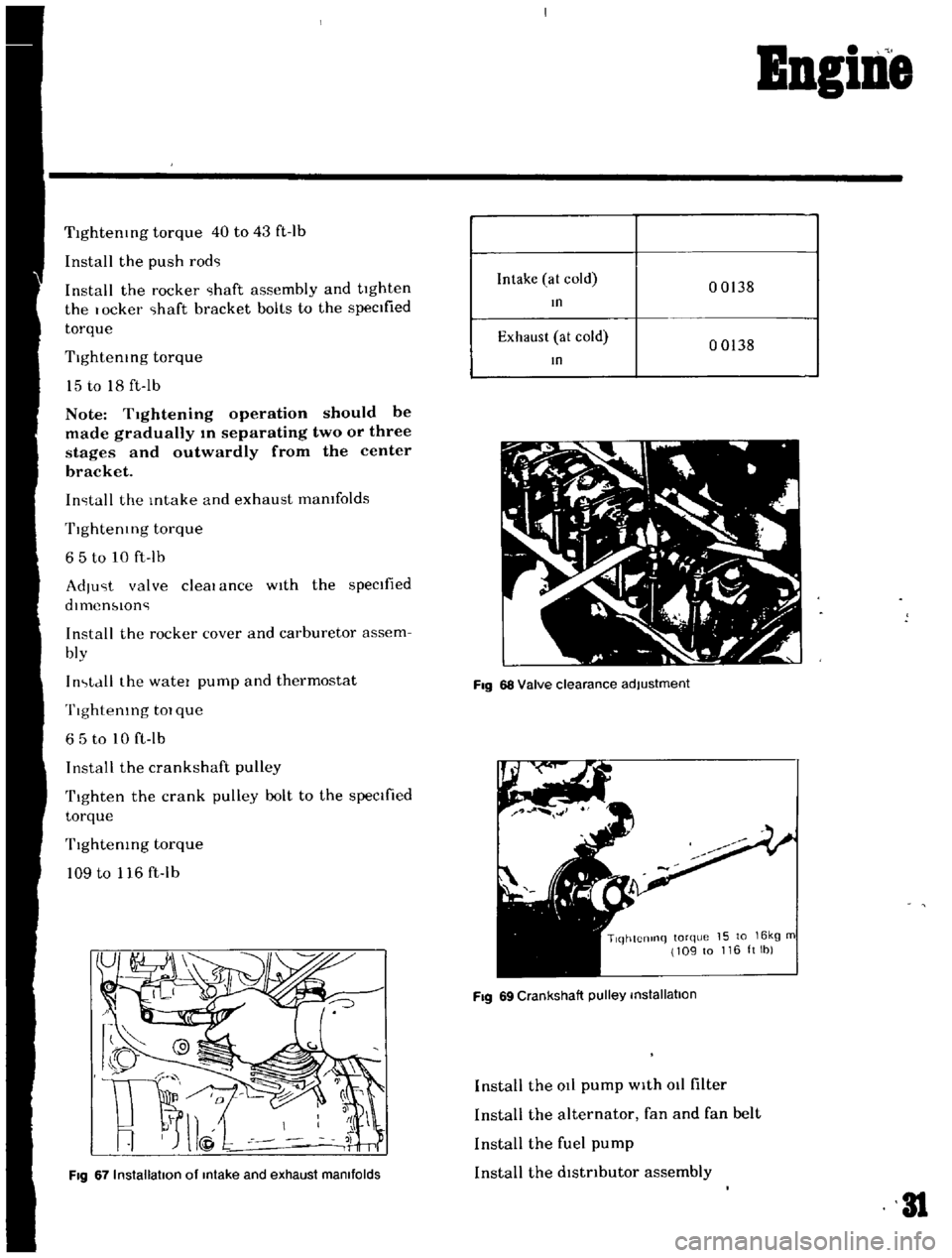
Fig
67
Installation
of
Intake
and
exhaust
manifolds
Intake
at
cold
00138
In
Exhaust
at
cold
00138
In
Fig
68
Valve
clearance
adjustment
TlqhtCnlnq
torque
15
to
16kg
m
109
to
116ltlb
Fig
69
Crankshaft
pulley
installation
Install
the
at
pump
with
011
filter
Install
the
alternator
fan
and
fan
belt
Install
the
fuel
pump
Install
the
dlstnbutor
assembly
31
Page 32 of 136
BBgiBe
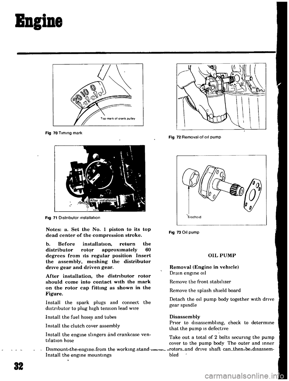
Fig
70
Tlmmg
mark
Fig
71
Dlstnbutor
mstallatlon
Notes
a
Set
the
No
1
piston
to
its
top
dead
center
of
the
compression
stroke
b
Before
installation
return
the
distributor
rotqr
approximately
60
degrees
from
Its
regular
position
Insert
the
assembly
meshing
the
distributor
drive
gear
and
driven
gear
After
installation
the
distributor
rotor
should
come
into
contact
wIth
the
mark
on
the
rotor
cap
fittmg
as
shown
in
the
Figure
Install
the
spark
plugs
and
connect
the
distrIbutor
to
plug
high
tensIOn
lead
wire
Install
the
fuel
hoses
and
tubes
Install
the
clutch
cover
assembly
Install
the
engme
shngers
and
crankcase
ven
tilatIOn
hose
Fig
72
Removal
of
011
pump
TrochoId
Fig
73011
pump
OIL
PUMP
Removal
Engine
in
vehlCIe
Dram
engme
OIl
Remove
the
front
stabilIzer
Remove
the
splash
shield
board
Detach
the
011
pump
body
together
with
drIve
gear
spmdle
Disassembly
PrIor
to
dlsassembhng
check
to
determme
that
the
pump
IS
defective
Take
out
a
total
of
2
bolts
securmg
the
pump
cover
to
the
pump
body
The
outer
and
mner
Dlsmount
the
engme
from
the
workmg
stand
rotors
and
drive
shaft
can
then
be
dlsassem
Install
the
engme
mountmgs
bled
32
Page 33 of 136
ApplYing
a
sUItable
wrench
or
spanner
loosen
off
the
regulator
valve
Note
a
When
placmg
the
valve
m
a
VIse
use
extreme
care
not
to
dIstort
the
pump
body
and
cover
in
the
jaws
b
Do
not
pull
out
the
drive
shaft
pin
securing
the
drIven
shaft
and
inner
rotor
The
shaft
is
press
fitted
to
the
rotor
with
the
pin
calked
Inspection
and
Repair
Clean
the
dIsassembled
parts
with
cleamng
solvent
and
Inspect
for
defects
Inspect
the
dnve
rotor
shaft
for
excessIve
wear
and
scores
and
check
the
follOWing
clearances
SIde
clearance
between
outer
and
Inner
rotors
0
0047
In
or
below
Tip
clearance
00016
to
0
0047
In
Clearance
between
outer
rotor
and
body
o
0059
to
0
0083
In
AdjustIng
Regulator
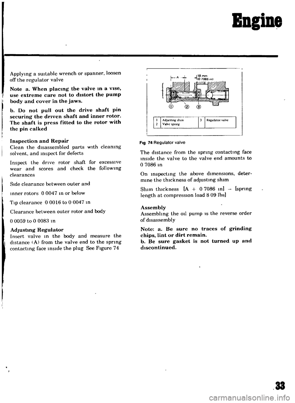
Insert
valve
In
the
body
and
measure
the
dIstance
A
from
the
valve
end
to
the
spnng
contacting
face
inside
the
plug
See
Figure
74
Bngine
1
Adjusting
h
rn
rJ
Regul
m
Valve
spnn
FIg
74
Regulator
valve
The
distance
from
the
spring
contacting
face
inSide
the
valve
to
the
valve
end
amounts
to
o
7086
m
On
inspecting
the
above
dlmenslOns
deter
mine
the
thickness
of
adjusting
shim
ShIm
thickness
A
0
7086
In
spring
length
at
compresslOn
load
809
lbs
Assembly
Assembhng
the
011
pump
IS
the
reverse
order
of
disassembly
Note
a
Be
sure
no
traces
of
grinding
chips
lint
or
dirt
remain
b
Be
sure
gasket
is
not
turned
up
and
dIscontinued
33
Page 34 of 136
11
1
r
t
i
4lI
t
it
j
t
rt
l
I
it
t
8
J
A
l
t
ty
1
1
J
t
1
r
t
d
V
i
f
r
1
t
r
p
J
i
K
l
j
F
p
ll
t
f
i1
AP
J
l
v
i
I
j
ll
f
r
f
1ll
0
0
l
t
l
l
pJ
Page 35 of 136
Bleatriall
System
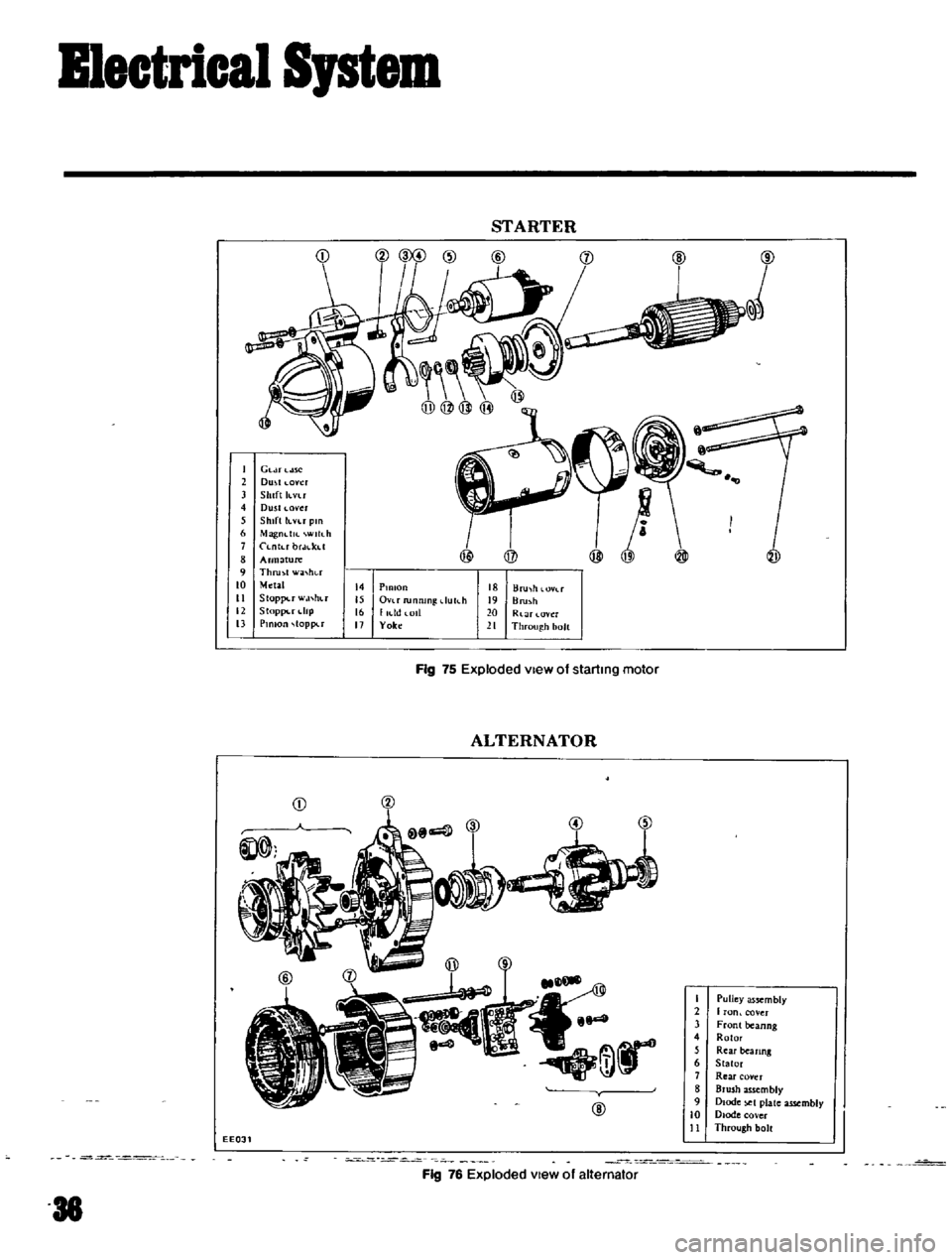
STARTER
I
Gl
U
ne
2
Dmt
oyer
3
Shift
h
vu
4
Dusll
ovcr
5
Shift
knr
pm
6
Magndlf
Wlllh
1
Lntubr
f
t
8
Arlll
ture
9
Thru
ot
w
L
ht
t
to
Metal
it
Stoppu
w
l
hu
12
Stoppt
rdlP
13
Pinion
toppu
@
@
@
@
I
15
16
17
Pmlon
Ovu
rumuRl
dukb
I
KId
lOll
Yok
18
Uru
h
19
Bru
l
b
20
Rl
ar
t
r
11
Through
bolt
Fig
75
Exploded
view
of
starting
motor
ALTERNATOR
CD
@OO
@
@
@
I
Pulley
assembly
2
f
on
cover
3
Front
beanng
4
Rotor
5
Rear
beanng
6
Stator
1
Rea
r
covet
8
Brush
assembly
9
Diode
t
plate
assembly
10
Diode
cover
11
Through
bolt
EE031
Fig
76
Exploded
view
of
alternator
Page 36 of 136
B1eetrical
Iptem
Removal
DIsconnect
the
battery
ground
cable
Disconnect
the
black
and
yellow
wIre
from
the
magnetic
sWitch
termmal
and
black
battery
cable
from
the
battery
termmal
Remove
two
bolts
used
to
secure
the
startmg
motor
on
the
clutch
housing
Pull
the
starter
assembly
forward
and
remove
the
starting
motor
Installation
InstallatlOn
IS
the
reversal
of
removal
Removal
Disconnect
the
negatIve
battery
termmal
DIsconnect
two
lead
wires
and
connector
from
the
alternator
Loosen
the
adjusting
bolt
Remove
the
alternator
drIve
belt
Remove
the
alternator
installation
bolt
Dismount
the
alternator
from
the
vehIcle
Installation
InstallatlOn
1S
the
reverse
of
removal
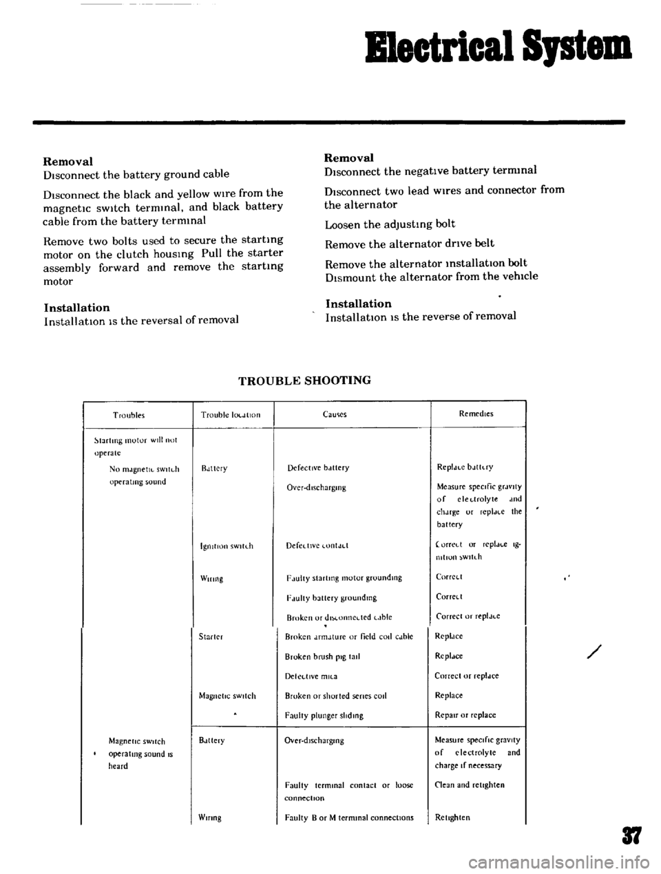
TROUBLE
SHOOTING
Troubles
Trouble
IOl
JlltHI
lartlTlg
motor
will
not
operate
No
mJgnetJl
sWltdl
operating
sound
Rdttcry
IgnitIon
sWltLh
Wiring
Starler
Magnetic
SWitch
Magnetic
SWitch
operating
sound
IS
heard
Bdttery
Wifing
CaUlies
Remedies
Defective
bclttery
Rcpldt
C
bJlh
ry
Over
dlschargmg
Measure
speCific
grJvlty
of
clcl
lrolyte
dnd
chJrge
ur
repl
H
e
the
battery
Defedlvc
lontJd
orreLl
or
replJl
c
Ig
mllun
wltdl
F
lulty
Slartmg
motor
groundlllg
CorrCl
l
F
lUlty
battery
groundmg
Corrcll
Broken
or
dlM
onncdcd
t
Jble
Carrece
or
replJt
c
Broken
dnnJture
or
field
coli
cJble
RcpldCC
Broken
brush
pig
tall
Rcpldce
Dekl
llVe
mll
3
Correcl
or
repldce
Broken
or
shorted
senes
cod
Replace
FaulIy
plunger
slidmg
RepaIr
or
replace
Over
dlschargmg
Measure
speCifiC
gravity
of
electrolyte
and
charge
If
necessary
Faulty
terminal
contact
or
loose
connectIOn
Clean
and
retighten
Faulty
B
or
M
termmal
connections
Rellghten
37
Page 37 of 136

Bmetrlcal
Spt
The
startmg
motor
rotates
PinIOn
gear
does
not
mtermec
h
with
flOg
gear
Pillion
mtermeshes
with
nng
gc
lT
Startmg
motor
roldles
Jud
pillion
Intermeshes
With
ring
gc
n
but
r
l
IlIan
IS
tou
slow
Startmg
motor
Magnetic
SWitch
Rmg
gear
Startmg
motor
Startmg
motor
Battery
Wiring
IgnitIOn
sWltl
h
Sldelmg
motor
38
Shorted
armature
or
field
cOIl
Worn
brush
or
Improper
spring
pressure
Contaminated
commutator
or
de
fective
mica
Faulty
brush
connection
Seized
metal
Armature
contacted
With
pole
core
Insufficient
plunger
L
dimenSIOn
Faulty
contact
Brok
en
or
shorted
shunt
call
wire
Worn
teeth
Weakened
pinion
sleeve
sprmg
Worn
pm
IOn
teeth
FJulty
plOlOJl
slldmg
Dropped
oft
lever
pill
EXl
hr
plunger
L
dlll1en
IOn
Defel
tlve
over
runnmg
dutch
Over
dlscharglOg
Improper
or
lome
termmdl
con
Lid
Improperly
tightened
connection
Rough
Lontact
urtJce
Shorted
armdture
COil
or
field
cOIl
Worn
brush
or
I11sufficlCnt
spnng
pressure
Conldmmated
Lomrnutator
or
Im
proper
brush
LonldLl
DercLllVe
nllca
Lack
or
metallubneallon
Armature
Lontdcted
With
pole
core
Repair
or
replace
Repair
or
replace
Cledn
or
repair
Repair
Replace
RepJlr
or
replace
AdjUst
ReplJee
Replace
ReplJee
Replnee
Rcpldce
RepJlr
Rep
m
Adjust
Re
place
Charge
battery
Repall
l11d
retIghten
Rellghten
RepJIr
or
replaLc
Repair
or
replace
Repair
or
replace
Repair
Repau
Repdlf
or
replace
Repair
or
replace
Page 38 of 136
llectrical
Spt
When
Harting
lWltch
I
IgllltlUn
iwltch
FJuhy
rctuflung
Repldce
set
10
OFf
the
slJrl
motor
do
nut
MJgnclK
Wltdl
Seiad
contJr
l
Repldcc
IIlg
I
op
Shorted
1
011
Replace
Faulty
plunger
slidmg
Replace
StJflillg
motOr
Pillion
does
not
dlsengJge
from
the
Repair
or
replace
nng
gedr
smoothly
Pinion
sphne
dot
110t
disengage
Repan
or
replJce
moothly
SCl7Cd
pinIOn
metal
Replace
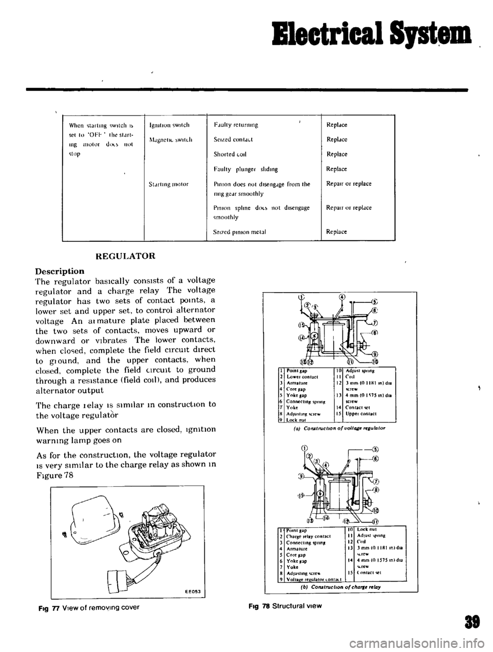
REGULATOR
Description
The
regulator
basically
consists
of
a
voltage
regulator
and
a
charge
relay
The
voltage
regulator
has
two
sets
of
contact
poInts
a
lower
set
and
upper
set
to
control
alternator
voltage
An
at
mature
plate
placed
between
the
two
sets
of
contacts
moves
upward
or
downward
or
Vibrates
The
lower
contacts
when
clo
ed
complete
the
field
CIrCUIt
dIrect
to
glOund
and
the
upper
contacts
when
closed
complete
the
field
CIrCUIt
to
ground
through
a
resIstam
e
field
COl
and
produces
alternator
output
The
charge
lelay
IS
SimIlar
In
constructIOn
to
the
voltage
regulator
When
the
upper
contacts
are
closed
IgnitIOn
warnIng
lamp
goes
on
As
for
the
constructIOn
the
voltage
regulator
IS
very
SImIlar
to
the
charge
relay
as
shown
In
Figure
78
I
POlnlsap
2
lower
nt
CI
3
Arm2fu1C
4
COfe
ap
5
Yokeg
lp
6
Connecting
pnn
t
T
Yolce
8
AdJu
fln
rcw
9
Lock
nul
Crew
13
4mmlOlli15
nldll
SCrew
14
RlaCI
I
15
Upper
Rlact
a
COlUlruci
o
o
voltage
ulato
O
0
1
EEOSJ
I
Point
gap
2
Char
Clay
nl3el
3
ConMctmg
pun
4
Armature
nl
daa
5
Core
ap
re
6
Yoke
Jap
14
4
mm
0
1575
n
dla
7
Yoke
rew
8
AdJu
llng
Cre
IS
nfaC
t
e1
9
Voila
ere
ulal0t
l
ontal
1
b
COfUtruclton
of
cha
rt
ay
FIg
n
View
of
removing
cover
FIg
78
Structural
view
81
Page 39 of 136

Blectrical
Sptem
Troubles
Trouble
locatIon
Not
output
Alternator
Regulator
WIring
Low
output
Alterndtor
Regulator
Wifing
TROUBLE
SHOOTING
Causes
Sl1ckmg
brushes
Duty
brushes
and
slIp
nngs
Loose
connections
or
broken
leads
Open
stator
coLI
Open
rotor
cotl
DefectIVe
dJodes
Shorted
rotor
Shorted
stator
Grounded
A
ternunal
Broken
fan
belt
FJulty
voltage
regulator
pomt
con
tact
Broken
cable
or
disconnectIOn
of
chargIng
CIH
UIt
StIcking
brushes
Low
brush
spring
tenSion
Duty
slIp
nngs
Partially
shorted
ground
or
open
stator
cod
Partially
shorted
or
grounded
rotor
c01l
DefectIVe
dIOde
Loose
or
worn
fan
belt
Improper
voltage
regulator
adlust
Pl
n
I
Faulty
voltage
regulator
pomt
con
t
ct
Defective
operation
Faulty
chargmg
CUI
Ult
lead
WIn
connection
Remedies
Correct
or
replace
brush
and
brush
spnng
aean
RetIghten
or
solder
connection
Replace
leads
If
necessary
6
RepaIr
or
replace
the
stator
coLi
Replace
the
rotor
Replace
the
dIOde
assembly
Replace
the
rotor
RepaIr
or
replace
the
stator
Replace
the
Insulator
Replace
the
belt
RepdU
01
replace
the
regulator
Repdtr
or
replace
Correct
or
replace
brushes
If
neces
sary
Correct
or
replace
brush
Clean
Replace
the
stator
Replace
the
rotor
Replace
the
dIode
assembly
Rettghlen
or
replace
the
belt
Check
the
voltage
regulalor
op
eratIOn
no
rep
Jr
r
J
j
required
Repair
or
replace
the
regulator
Re
olf
or
rpla
e
t
J
Loose
baltery
leririmaJ
Rettghten
1
Page 40 of 136
i
J
t
1
p
3
t
t
i
I
EXCCS
lVe
output
Alterndlor
P
Short
l
lfculted
or
broken
neutral
Replace
the
wife
Wife
Reguldtor
Impro
er
voltdge
regulator
adJust
ment
Defective
operatIon
9i
reg
ator
oP
P
lor
replace
as
rw
t
Check
the
charge
relay
operation
and
repair
or
replace
as
requIred
Check
the
voltage
t
fa
hon
and
ep
lf
required
Improper
charge
relay
adjustment
detecttve
operatIOn
and
or
faulty
pomt
contact
t
f
J
r
p
i
lC
I
1
1
r
i
r
A
1
A
f
l
1
1
S
1
P
1